

Quick Answer
A solar lightning arrester is an air terminal that intercepts direct lightning strikes before they hit PV modules, racking, or conductors. It works as part of an external lightning protection system with down conductors and earth electrodes. Selection depends on protection radius, site lightning density, and whether the array sits above or apart from an existing building LPS.
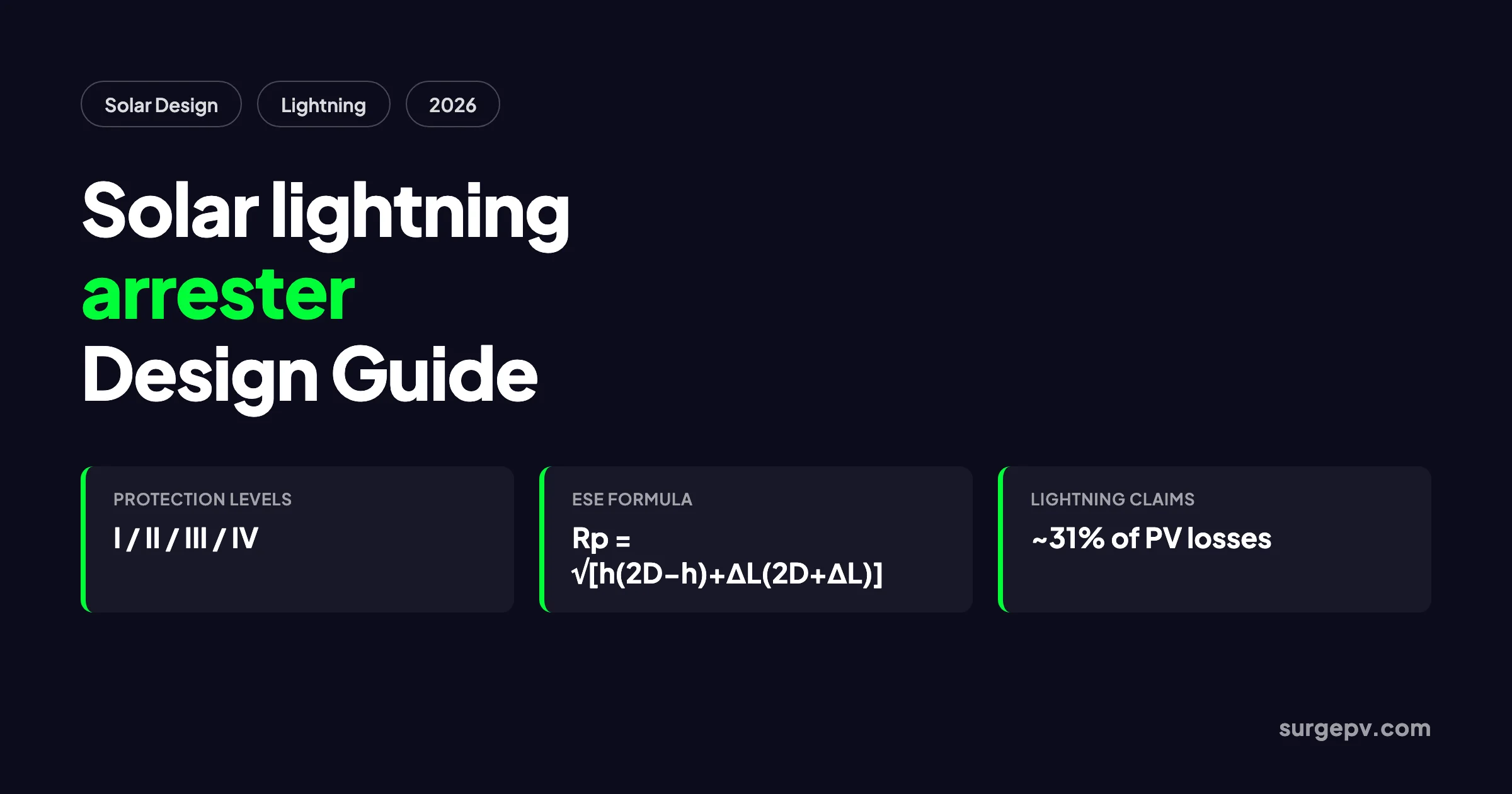
Lightning is one of the largest causes of avoidable loss in solar plants. A correctly sized solar lightning arrester is the first line of defense. Industry data from Germany showed that lightning accounted for roughly 31% of photovoltaic system damage claims between 2005 and 2014 (PLOS ONE, 2019; PSC Consulting, 2024). Typical losses include inverter damage, module defects, and cable insulation failure. A single strike can transfer 20–200 kA in microseconds. No inverter, fuse, or surge protector can absorb that energy.
This guide is for designers, installers, and EPC engineers who need to specify air terminals for PV arrays. It explains how a solar lightning arrester works. It covers how to choose between Franklin rods and early streamer emission, or ESE, arresters. It also shows how to calculate protection radius. It also covers the standards that govern placement and the mistakes that turn a protection system into a warranty claim. You can model array geometry, cable routing, and zone boundaries in SurgePV so the lightning design stays in sync with the rest of the electrical layout.
In this guide:
- What a solar lightning arrester is and is not
- How air terminals, down conductors, and earth electrodes work together
- Franklin rod vs ESE arrester vs mesh cage
- Protection radius calculations with a worked example
- Sizing and placement rules for rooftop and ground-mount arrays
- Compliance with IEC 62305, NFPA 780, IS 2309, and NFC 17-102
- Common mistakes that fail inspection or destroy inverters
- How arresters coordinate with SPDs and grounding
- How solar design software automates the documentation
Quick Answer
A solar lightning arrester is an air terminal that intercepts direct lightning strikes before they hit PV modules, racking, or conductors. It works as part of an external lightning protection system with down conductors and earth electrodes. Selection depends on protection radius, site lightning density, and whether the array sits above or apart from an existing building LPS.
What Is a Solar Lightning Arrester?
A solar lightning arrester is the air terminal component of an external lightning protection system. Its job is to become the preferred strike point. It captures lightning current, conducts it down the structure, and dissipates it into the earth before the current can enter the PV array or building.
The term is often confused with surge protective devices. In solar documentation, “lightning arrester” usually refers to the external air terminal, while “SPD” refers to the internal device that clamps transient overvoltages on circuits. Both protect the system, but against different threats. The arrester handles direct strikes. The SPD handles induced surges from nearby strikes and switching events.
A complete external lightning protection system has three parts:
- Air termination network: rods, masts, or mesh conductors placed where lightning is most likely to strike.
- Down conductors: low-impedance paths that carry current from the air terminal to the earth.
- Earth termination network: electrodes and soil contact that dissipate the current safely.
For a solar array, the air terminal must protect the full collection area of modules, combiner boxes, and any exposed inverter housing. That sounds simple, but the geometry of modern arrays makes it easy to leave corners or elevated rows outside the protected volume.
How a Solar Lightning Arrester Works
Lightning begins when a downward stepped leader from a storm cloud approaches the ground. Grounded metal objects respond by launching upward streamers. The object whose upward streamer meets the downward leader first becomes the strike point. A lightning arrester is designed to win that race within a defined protected volume.
When the strike attaches to the arrester, the current travels down the conductor and into the earth. The goal is to keep the current outside the building or array electrical system. If the current instead enters module frames, DC cabling, or inverter enclosures, the result is melted connectors, shattered glass, and destroyed electronics.
The protection is not absolute. Arresters reduce the probability of a direct strike to the protected object to a tolerable level defined by the standard. IEC 62305-2 sets that tolerable risk based on the type of structure and its contents. A hospital data center and a residential garage have different thresholds.
Solar arrays add three complications:
- Large horizontal area. A ground-mount array can cover hectares of flat land. The protected volume must cover every row.
- Elevation. Rooftop arrays are often the highest conductive surface on the building.
- Long conductor runs. DC cables between modules and inverters act as antennas for induced surges even when the array is not directly struck.
That third point is why external arresters alone are not enough. Indirect strikes within a few hundred meters can induce 2,000–8,000 V transients on DC cabling. Modeling has shown that a 5 kA strike can drive hundreds of amperes near a PV array (MDPI Energies, 2017). Those transients are clamped by SPDs, not by the air terminal.
Types of Solar Lightning Arresters
The choice of arrester type depends on site risk, array geometry, local code acceptance, and maintenance access. The three main options for solar are Franklin rods, early streamer emission arresters, and mesh or cage systems.
Franklin Rod
A Franklin rod is a simple metal rod mounted on a mast. It is the oldest and most widely accepted form of air terminal. It works by providing a sharp, elevated point from which an upward streamer can develop.
Franklin rods are inexpensive, require little maintenance, and are recognized by IEC 62305 and NFPA 780. Their disadvantage is limited coverage. Each rod protects a relatively small volume, so large arrays need many masts. The design is done using the rolling sphere method or the protection angle method.
Early Streamer Emission Arrester
An ESE arrester uses an ionization device to launch an upward streamer earlier than a passive rod of the same height. The earlier streamer extends the effective collection radius, which means one ESE mast can sometimes replace several Franklin rods.
ESE arresters are governed by NFC 17-102 in France and several other countries, and by UNE 21186 in Spain. They are accepted in many parts of Africa, the Middle East, Asia, and Latin America. However, they are controversial in some markets because independent test evidence of real-world performance is mixed. Germany’s VDE does not recognize ESE technology, and some insurers in northern Europe require conventional systems.
For solar EPCs working across multiple countries, the key is to specify what the local authority having jurisdiction accepts. An ESE design that passes in India or the UAE may not pass in Germany or parts of the United States.
Mesh or Cage System
A mesh system uses a network of conductors over the protected structure. It is common on buildings with large flat roofs and on inverter or control buildings within a solar farm. The mesh is effectively a Faraday cage that distributes current and prevents direct attachment to objects inside.
For solar arrays, mesh is sometimes used over inverter stations, storage containers, or control rooms. It is less common over the module field itself because it creates shading and mechanical loading issues.
| Arrester Type | Best For | Coverage | Key Standard | Maintenance |
|---|---|---|---|---|
| Franklin rod | Small arrays, rooftop systems, low-risk sites | Small per mast | IEC 62305-3, NFPA 780 | Low |
| ESE arrester | Large open sites, high lightning density, fewer masts desired | Large per mast | NFC 17-102, UNE 21186 | Medium |
| Mesh/cage | Buildings, inverter stations, control rooms | Full roof or enclosure | IEC 62305-3, NFPA 780 | Low |
Protection Radius and Coverage Calculations
The protected volume of an air terminal is the three-dimensional space inside which a direct strike is unlikely to hit the object. Two methods dominate solar design: the rolling sphere method and the ESE protection radius formula.
Rolling Sphere Method
The rolling sphere method comes from IEC 62305-3 and NFPA 780. Imagine a sphere with a radius equal to the rolling sphere radius for the selected protection level. The sphere is rolled over the array and supporting structures. Any point the sphere can touch is unprotected. Points the sphere cannot touch because they are shielded by an air terminal are protected.
The rolling sphere radius depends on the protection level:
| Protection Level | Rolling Sphere Radius | Typical Use |
|---|---|---|
| Level I | 20 m | High consequence: hospitals, explosives, critical infrastructure |
| Level II | 30 m | Commercial and industrial buildings |
| Level III | 45 m | Ordinary structures, many solar farms |
| Level IV | 60 m | Low-risk structures |
For a solar array, the designer places air terminals so that the rolling sphere cannot touch the highest module row, inverter housings, or any exposed metallic structure. Software tools are useful here because manual sphere visualization over irregular rooftops is error-prone.
Protection Angle Method
The protection angle method is a simplified way to estimate coverage from a single mast or rod. Draw a line from the tip of the air terminal down at the protection angle for the selected level. Anything under that line is considered protected.
The angle decreases as the structure height increases. At Level III, a rod up to 20 m high may use a protection angle of about 45°. A taller structure may use 35° or less. The method is conservative and is generally only accepted for simple geometries.
ESE Protection Radius Formula
For ESE arresters, NFC 17-102 gives the protection radius at a given height h:
Rp = √[ h(2D − h) + ΔL(2D + ΔL) ]
Where:
- Rp = protection radius in meters
- h = height of the ESE tip above the horizontal plane through the point to be protected, in meters
- D = rolling sphere radius for the protection level: 20, 30, 45, or 60 m
- ΔL = advance trigger distance in meters, equal to ΔT × 10^6, with ΔT in seconds. For an ESE rated at 30 µs, ΔL = 30 m.
Worked Example
A ground-mount solar farm in a high-risk region selects Protection Level I, so D = 20 m. The ESE arrester is rated for ΔT = 30 µs, giving ΔL = 30 m. The mast raises the ESE tip 8 m above the highest module row.
Rp = √[ 8 × (2 × 20 − 8) + 30 × (2 × 20 + 30) ] Rp = √[ 8 × 32 + 30 × 70 ] Rp = √[ 256 + 2,100 ] Rp = √2,356 Rp ≈ 48.5 m
At that height, one arrester protects a circular area with roughly a 48 m radius. In practice, designers overlap zones and account for terrain, tracker movement, and future expansion. The calculation also assumes the arrester is at least 2 m above any object it protects. Coverage below 2 m is not credited under NFC 17-102.
Sizing and Placement Rules for Solar Arrays in 2026
Once the protection radius is known, the designer must decide how many arresters are needed and where they go. The goal is full coverage of the array collection area without creating new problems.
Rooftop Arrays
For rooftop residential and commercial systems, the first question is whether the building already has an LPS. If it does, the array should be inside the existing protected volume. If it is not, either extend the existing LPS or add a dedicated mast.
Key rules:
- The air terminal must be the highest metallic object in the protected zone.
- Keep the terminal at least 2 m above the highest panel row or parapet.
- Do not mount arresters directly on module frames or thin rail sections without structural review.
- Bond the array frame and racking to the LPS equipotential bar, not to a random earth pit.
Ground-Mount Arrays
Ground-mount arrays are exposed across a wide area. They are often the tallest object in an open field, which increases collection area. Designers typically use:
- Perimeter masts placed around the array field.
- Internal masts if the array width exceeds twice the protection radius.
- Mesh or catenary wires over inverter stations and control buildings.
Tracker arrays add a complication. The module row height changes with tilt angle. The designer must check coverage at both stow position and maximum tilt. A tracker row that tilts into an unprotected zone at midday is a warranty waiting to happen.
Separation Distance
Separation distance is the clearance between the external LPS and internal metalwork. If a strike to the LPS is too close to a module frame or cable, the voltage difference can spark across the gap. The formula from IEC 62305-3 is:
s = ki × (kc / km) × l
Where:
- s = required separation distance
- ki = factor depending on protection level
- kc = factor depending on down conductor arrangement
- km = factor depending on material
- l = length along the down conductor from the point considered to the equipotential bonding point
If the required distance cannot be maintained, the metallic parts must be bonded to the LPS at that point. That bonding is often done through SPDs or direct conductors.
Standards and Compliance
Solar lightning arrester design is governed by national and international standards. The designer must know which standard the authority having jurisdiction has adopted.
IEC 62305
IEC 62305 is the international lightning protection standard. It has four parts:
- Part 1: General principles
- Part 2: Risk management
- Part 3: Physical damage to structures and life hazard
- Part 4: Electrical and electronic systems within structures
Part 2 determines whether an LPS is needed. Part 3 defines the rolling sphere method, mesh method, and protection angle method. Part 4 covers internal SPDs and lightning protection zones.
NFPA 780
NFPA 780 is the United States standard for lightning protection system installation. It covers air terminals, conductors, grounding, and bonding. It is referenced by many insurance underwriters and some building codes. NEC Article 285 and 230.67 address surge protection devices, but they do not design the external LPS. That is NFPA 780’s role.
IS 2309 and Indian Practice
In India, IS 2309 applies to lightning protection of structures. Many state DISCOMs and CEA guidelines require rooftop solar systems to include lightning protection and SPDs. The Indian market also uses ESE arresters widely. Designers should verify that the selected product has NFC 17-102 test reports. They should also confirm that the local electrical inspector accepts ESE technology.
NFC 17-102
NFC 17-102 is the French standard for early streamer emission arresters. It defines the test method for ΔT, the protection radius formula, and installation requirements. It is adopted directly or by reference in many francophone and Middle Eastern markets.
Product Standards
The arrester itself is only one component. Down conductors, clamps, and earth electrodes should meet IEC 62561 or UL 96A. SPDs must meet IEC 61643-31 for DC PV applications or UL 1449 for North American systems.
Common Solar Lightning Arrester Mistakes
Most lightning protection failures are not caused by missing arresters. They are caused by correct arresters installed the wrong way. Here are the mistakes that show up most often in warranty claims and inspection failures.
Relying on Arresters Alone
An air terminal does nothing for induced surges. A nearby strike can induce thousands of volts on DC cabling without ever touching the array. The fix is coordinated SPDs at combiner boxes, inverter inputs, and AC service entrances. The external LPS and internal SPDs are a system, not alternatives.
Wrong Earth Connection
The most damaging mistake is bonding the lightning earth and the equipment earth to the same pit. During a strike, the local ground potential can rise by thousands of volts. If the inverter earth shares that pit, the surge finds its way into the AC and DC circuits. Lightning protection earth and equipment earth should be separate pits, bonded together at one equipotential bar.
Long Down-Conductor Leads
SPD performance depends on lead length. Long, looping conductors increase inductance and raise clamping voltage at the protected equipment. Keep SPD leads under 0.5 m and route them with minimal loop area. The same rule applies to bonding jumpers between racking and the LPS.
Ignoring Tracker Movement
A ground-mount tracker changes height and tilt throughout the day. A protection study done only at flat stow position may miss the highest tilt angle. The designer should model the tracker at maximum tilt, maximum azimuth, and stow position.
Using Residential Rules on Commercial Sites
A Type 2 SPD and a single Franklin rod may be adequate for a 5 kW rooftop system in a low-risk region. A 10 MW solar farm in Florida or Rajasthan needs a full risk assessment. Florida sees more than 14 flashes/km²/year in parts of the peninsula (NOAA, 1994). These large sites need multiple ESE or conventional masts, Type 1+2 SPDs, and documented inspection records. Applying residential rules to utility-scale sites is a common source of denied insurance claims.
Coordinating Arresters with SPDs and Grounding
A solar lightning arrester and an SPD protect against different energy paths. Coordination means the energy is managed in stages.
Layer 1: External Arrester
The air terminal captures the direct strike current and routes it to earth. The current is large, 20–200 kA, but the duration is short. The path must be low impedance and kept outside the electrical system.
Layer 2: Type 1 SPD
A Type 1 SPD is tested with the 10/350 µs waveform, which represents partial direct-strike current. It goes at the boundary between LPZ 0 and LPZ 1, such as where DC cables enter a building that has an external LPS. Type 1 SPDs are mandatory when there is a risk of partial lightning current entering the building.
Layer 3: Type 2 SPD
A Type 2 SPD is tested with the 8/20 µs waveform, which represents induced surges. It goes at inverter DC inputs, inverter AC outputs, and distribution boards. Type 2 SPDs clamp the residual voltage from Type 1 SPDs and protect sensitive electronics.
Grounding and Bonding
All metallic parts of the array, including module frames, racking, conduit, and inverter enclosures, must be bonded to the same equipotential reference. The bonding prevents dangerous voltage differences during a surge. The earth termination system must have low enough resistance to dissipate the strike current. Many specifications target an earth resistance below 5 Ω, though the exact requirement depends on soil resistivity and local code.
The global DC surge arrester market was valued at approximately $875 million in 2026 (Future Market Insights, 2026). It is projected to reach $1.64 billion by 2036, growing at 6.5% annually. That growth reflects how seriously developers are taking surge protection as arrays scale.
Design Lightning Protection Inside Your Solar Layout
SurgePV captures array geometry, string layouts, and zone boundaries in one model. Update protection zones automatically when the design changes, export SLD-ready drawings, and coordinate SPD placement with the electrical plan.
Book a DemoNo commitment required · 20 minutes · Live project walkthrough
Design Automation with SurgePV
Manual lightning protection calculations become tedious as arrays grow. A 10 MW site may have thousands of module rows, multiple inverter stations, and varying terrain. Solar design software should do three things for lightning protection:
- Store the array geometry. Module row heights, tracker tilt ranges, and inverter locations feed directly into the protection volume calculation.
- Flag unprotected zones. The software can run a rolling sphere or protection radius check across the full array and highlight rows that sit outside the protected volume.
- Coordinate with electrical design. When the array layout changes, the SPD locations, down conductor routes, and earth pit positions should update automatically.
SurgePV also connects the lightning study to the rest of the project. Irradiance and shading analysis checks whether new masts cast shade on modules. The system size calculator and wire size calculator keep conductor sizing consistent with the protection design.
For a deeper look at SPD selection and placement, see the companion guide on solar lightning protection. For fault current and overcurrent protection sizing, see the solar fault current design guide.
Frequently Asked Questions
What is a solar lightning arrester?
A solar lightning arrester is an air terminal installed above or beside a PV array to intercept direct lightning strikes. It forms the first layer of an external lightning protection system. Down conductors and earth electrodes then route strike current into the ground before it reaches modules, inverters, or cabling.
What is the difference between a lightning arrester and a surge protection device for solar?
A lightning arrester is an external air terminal that protects against direct strikes. A surge protection device, or SPD, is an internal component that clamps induced voltage surges on power and data circuits. Both are needed: the arrester handles direct hits, while SPDs handle the electromagnetic surges from nearby strikes.
How do you calculate the protection radius of a solar lightning arrester?
For a conventional Franklin rod, use the rolling sphere method from IEC 62305-3 or the protection angle method. For an early streamer emission, or ESE, arrester, use the NFC 17-102 formula Rp = √[h(2D − h) + ΔL(2D + ΔL)]. In that formula, h is height above the protected surface. D is the sphere radius for the chosen protection level. ΔL is the advance trigger distance.
When is a lightning arrester mandatory for a solar installation?
A lightning arrester is required when a risk assessment shows the tolerable risk is exceeded. IEC 62305-2 and NFPA 780 use local ground flash density, array collection area, and consequence of damage to decide. In India, IS 2309 applies to rooftop solar structures, and CEA grid codes often require SPDs for systems above 10 kW.
Should a solar lightning arrester share the same earth pit as the inverter?
No. The lightning protection earth should be a separate physical pit, bonded to the equipment earth at one equipotential bar. Sharing a single pit can raise local ground potential during a strike and backfeed surge current into the inverter, control circuits, and communication lines.
What is the best type of lightning arrester for a solar power plant?
The best type depends on site risk and array layout. Conventional Franklin rods or meshes are simple, low-maintenance, and widely accepted under IEC 62305. ESE arresters can cover larger areas with fewer masts but are regulated differently by region. Ground-mount solar farms in high-risk zones often use a combination of ESE masts and mesh cages.
How high should a solar lightning arrester be above the panels?
An air terminal should be the highest metallic point in the protected zone. For ESE arresters, NFC 17-102 coverage is generally not credited below 2 m above the protected object. The protection radius improves significantly once the arrester is 5 m or more above the surface. For rooftop arrays, the terminal should clear the highest panel row by at least 2 m.
How often should a solar lightning protection system be inspected?
Inspect residential systems every 6 months and commercial or utility-scale systems monthly. Check earth resistance annually. Inspect down conductors and bonds after severe weather. Test or replace SPDs after any confirmed strike or when status indicators show failure.
Where this fits
This article is part of SurgePV's Solar Design hub, which works through the topic from first principles to the decisions a project team actually has to make.


