

Fault current is the number that decides whether a solar plant survives a short-circuit or burns a cable. Every conductor, fuse, breaker, and switchgear busbar must be rated for the maximum current that can flow during a fault. In PV systems the calculation is different from conventional power systems because modules are current-limited sources and inverters are electronic converters, not rotating machines. Designers who treat a solar array like a small utility feeder get the protection wrong.
This guide explains how to calculate solar fault current in 2026. It covers DC faults inside the array, AC faults on the inverter output, the small but real contribution from inverters, and the larger contribution from battery storage. It also walks through the code requirements in NEC Article 690 and IEC 60364-7-712, and shows how to size overcurrent protection so the device closest to the fault clears first. You can model the same workflow in SurgePV without running separate hand calculations for every iteration.
In this guide:
- What solar fault current is and why it is not like utility fault current
- How PV modules limit DC fault current
- The NEC 690.8 and IEC 60364-7-712 calculation rules
- AC fault current sources: grid, transformer, inverter, and battery
- How to size fuses, breakers, and interrupting ratings
- Common fault current mistakes that fail inspection
- A worked example for a 500 kW commercial rooftop
- How solar design software automates the checks
Quick Answer
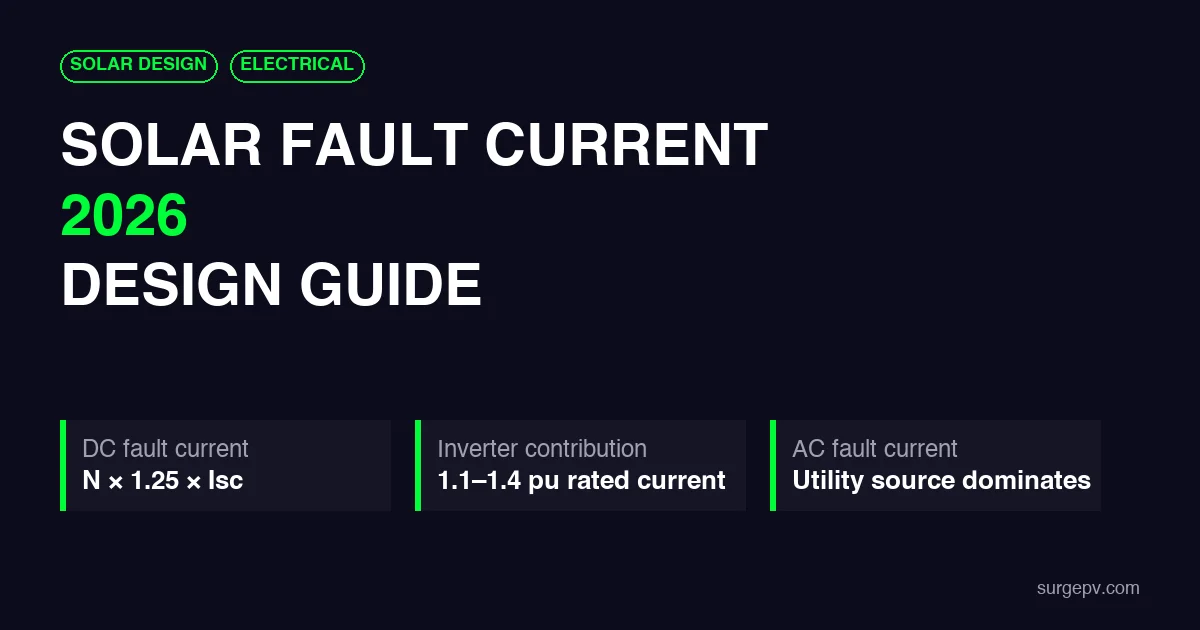
Solar fault current is the current that flows when a short-circuit or ground fault occurs in a PV system. On the DC side it is limited by module short-circuit current and the number of parallel strings. On the AC side the utility source dominates, while inverters add only 1.1 to 1.4 per-unit of rated current for a few cycles.
What Is Solar Fault Current?
A fault current is any abnormal current that flows when insulation fails or conductors touch where they should not. In a PV system the most common faults are:
- Bolted short circuit: two conductors connect with very low resistance.
- Line-to-ground fault: a live conductor touches the frame, racking, or earth.
- Line-to-line fault: the positive and negative conductors of a string or array short together.
- Arcing fault: current crosses a gap through plasma, creating high heat without a solid short.
Each fault type produces a different current. A bolted fault gives the highest prospective current and is used to size equipment. A ground fault may be limited by grounding resistance. An arc fault has lower current than a bolted fault but can start a fire because the arc energy stays concentrated at the fault point.
The short-circuit current of a module, written Isc, is the maximum current the module can produce when its terminals are shorted. It is measured at Standard Test Conditions: 1,000 W/m² irradiance and 25°C cell temperature. In real systems the fault current can be higher than STC Isc because of cloud-edge brightening, snow reflection, or bifacial rear-side gain. That is why codes apply a safety multiplier.
Why Solar Fault Current Is Different
Conventional AC systems are fed by transformers connected to a stiff grid. When a fault occurs, the transformer delivers many times normal current. Synchronous generators can produce 6 to 10 times rated current for the first few cycles. Solar PV does not behave this way.
A PV module is a current-limited source. It cannot deliver more current than the photons hitting the cell can generate. Its short-circuit current is typically only 5% to 15% above its maximum-power current. A fault in a single string therefore sees at most 1.25 to 1.56 times the string Isc, depending on the code factor.
Parallel strings change the picture. When N strings connect to the same combiner bus, a fault on one string can be fed by the other N-1 strings. The total current becomes the sum of their contributions. A 24-string combiner with 14 A Isc modules can see more than 330 A of reverse fault current into a faulted string.
| Property | DC PV Fault Current | AC Utility Fault Current |
|---|---|---|
| Source | PV modules and strings | Utility transformer and grid |
| Current limit | Module Isc × safety factor | Transformer impedance and grid strength |
| Typical magnitude | Hundreds of amps per combiner | Thousands to tens of thousands of amps |
| Duration | As long as the sun shines | Decays over cycles but sustained until cleared |
| Protection | gPV fuses and DC-rated breakers | AC breakers and relays |
On the AC side, the inverter is also current-limited. Grid-tied inverters use fast software current limiters and hardware overcurrent shutdowns. Their sustained fault contribution is usually between 1.1 and 1.4 per-unit of rated current according to IEEE 1547-2018 smart inverter guidance. The real AC fault current comes from the utility transformer and the upstream grid.
How to Calculate DC Fault Current
The DC side of a PV array has no rotating machines and no infinite bus. The maximum prospective fault current is the sum of the currents that every healthy source can push into the fault.
Module and String Level
A single module produces Isc_STC under short-circuit conditions. When modules are connected in series to form a string, the string current stays the same as a single module. The string voltage adds. So a string of 20 modules with 14 A Isc still produces 14 A into a bolted fault.
NEC 690.8(A)(1)(a)(1) sizes the maximum circuit current as 1.25 times the module Isc. The 2026 NEC revision clarifies that the calculation must use the highest short-circuit current rating of the modules connected in parallel. This matters for bifacial modules, which can carry multiple Isc values, according to Electrical License Renewal.
IEC 60364-7-712 takes a similar approach. The design current for PV circuits is Isc multiplied by a factor K_I. The minimum value of K_I is 1.25, as noted in the IEC 60364-7-712 guide from Atlas Bridge.
Combiner and Array Level
When strings are connected in parallel, currents add. The worst-case DC fault current at a combiner box is usually calculated as:
I_fault_DC = (N - 1) × Isc_module × 1.25
Where N is the number of parallel strings in the combiner. The factor 1.25 accounts for irradiance above STC. Some standards use 1.56 for protection sizing, but the prospective fault current used to check breaking capacity is typically the 1.25 value.
A fault on the combiner output bus, rather than inside one string, can be fed by all N strings. In that case the current is:
I_fault_DC = N × Isc_module × 1.25
The Mersen technical topic on line-line fault analysis and protection in PV arrays explains how reverse current from parallel strings flows through a faulted string. It also shows why string fuses are required when three or more strings are paralleled.
Bifacial and Temperature Effects
Bifacial modules can produce additional current from rear-side irradiance. The 2026 NEC addresses this by requiring the highest Isc rating marked on the module or in the listing instructions. The rear-side gain is not a fixed percentage. It depends on ground albedo, row spacing, and tilt. Designers should use the module manufacturer’s bifacial Isc values rather than adding a flat margin.
Temperature has a small positive effect on current. The Isc temperature coefficient is typically +0.04%/°C. A 50°C cell temperature raises Isc by about 1% compared with STC. This is small compared with irradiance enhancement and is usually absorbed by the code safety factor.
AC Fault Current: Utility, Transformer, and Inverter Contributions
The AC side of a grid-tied PV plant sees fault current from three sources. Two of them matter far more than the third.
Utility Fault Current
The dominant source is the utility grid. The service transformer steps utility voltage down to the plant voltage. Its impedance limits the fault current. A 1,000 kVA transformer with 5.75% impedance at 480 V delivers about 20.9 kA of three-phase fault current at its secondary terminals, assuming an infinite primary bus. That is the number the AC switchgear and breakers must survive.
Real systems are not fed from an infinite bus. The utility provides an available fault current at the primary side. A full short-circuit study combines the utility source, transformer impedance, cable impedances, and motor contributions to give the prospective fault current at each bus.
Inverter Contribution
Inverters contribute little sustained fault current. Their semiconductors cannot survive overcurrent, so software limiters cap the output. According to Industrial Monitor Direct, most PV inverters are limited to 1.1 to 1.2 per-unit of rated current. Some designs reach 1.4 per-unit for a short time. After a few cycles the inverter either trips or enters a ride-through mode with controlled current.
This small contribution means inverter-based resources do not usually change the AC breaker interrupting rating. However, it does change protection coordination. Traditional overcurrent relays assume a large infeed from downstream sources. With PV, the downstream contribution may be too small to help a relay distinguish between a fault and normal overload.
Battery Storage Contribution
A battery energy storage system is the exception to the low-fault-current rule. Lithium-ion batteries have very low internal resistance. A fault on the battery DC bus can produce thousands of amps. The battery inverter or converter may also contribute current to an AC fault, depending on its control settings.
Battery protection must be sized from the battery fault current, not the PV Isc. This usually requires a separate DC fuse or breaker at the battery terminals, plus a disconnecting means that can safely break the prospective current. For a deeper look at combining PV and storage, see our guide to DC vs AC coupling for solar-plus-storage.
Sizing Overcurrent Protection for Fault Current
An overcurrent protection device must do two things. It must carry normal current indefinitely, and it must interrupt the prospective fault current without destroying itself.
Interrupting Rating
The interrupting rating, also called breaking capacity or AIC in North America, is the maximum fault current the device can safely open. On the DC side it is written in kA DC. On the AC side it is written in kA RMS symmetrical. A device installed where the prospective fault current is 20 kA needs an interrupting rating above 20 kA.
Standard AC breaker AIC ratings are 10 kA, 22 kA, 42 kA, 65 kA, and 100 kA. DC gPV fuses commonly have interrupting ratings from 10 kA to 50 kA at 1000 or 1500 VDC.
Voltage Rating
DC arcs do not self-extinguish at current zero crossings like AC arcs. A fuse or breaker rated for 600 VAC may fail catastrophically at 600 VDC. PV string fuses must be listed as gPV per IEC 60269-6 or UL 2579. PV breakers must carry a DC voltage rating at least equal to the maximum system voltage, which is the temperature-corrected open-circuit voltage.
Short-Circuit Current Rating of Equipment
Breakers and fuses are not the only parts that must survive a fault. Every panelboard, disconnect, combiner box, and busbar carries a short-circuit current rating (SCCR). The SCCR is the maximum fault current the equipment can withstand while the overcurrent device clears. If the available fault current at the equipment terminals is 22 kA and the SCCR is only 10 kA, the enclosure or busbar can fail before the breaker opens.
Combiner boxes are often marked with a maximum short-circuit current rather than an SCCR in the traditional sense. The label might say the box is rated for a total input short-circuit current of 400 A or 600 A. That limit must not be exceeded by the sum of string Isc values multiplied by the code factor. When arrays grow, designers sometimes exceed the combiner SCCR without noticing because they only checked the fuse rating.
Series ratings also matter. A series-rated breaker combination is tested as a pair, where the upstream breaker limits current enough to protect the downstream breaker. The rating is valid only for the exact pair listed on the panelboard label. Swapping one breaker for a different brand can void the rating.
Current Rating and Code Factors
NEC 690.9 sizes the OCPD for a PV source circuit at not less than 1.56 times Isc. The factor comes from 1.25 for irradiance enhancement multiplied by 1.25 for continuous duty. For a module with 14 A Isc, the minimum OCPD rating is 14 × 1.56 = 21.8 A, rounded up to the next standard size of 25 A. Our solar fuse sizing guide walks through the exact steps.
IEC 60364-7-712 uses a different window. The fuse rating must be at least 1.25 × Isc and no more than 2.4 × Isc, and it must stay below the module maximum reverse-current rating. This often leads to a smaller fuse than the NEC method for the same module.
Coordination
Sizing a device for fault current is only half the job. The devices must also coordinate so that the closest device clears first. If a string fault trips the combiner main, the whole combiner goes offline. For coordination rules, see our guide to overcurrent protection coordination in solar PV.
Common Solar Fault Current Mistakes
These errors show up repeatedly in design reviews and failed inspections.
Using AC-Rated Breakers on DC Circuits
An AC breaker is not a DC breaker. At the same voltage, a DC arc is harder to interrupt. Using an AC-rated device in a PV string circuit is a fire risk and a code violation. Always check for the DC voltage rating and the DC interrupting capacity.
Ignoring the Inverter Contribution
While inverter fault current is small, it is not zero. Protection studies that ignore the inverter can misjudge relay settings. In weak grids with low short-circuit ratios, even a 1.2 per-unit inverter contribution can change the measured fault current enough to affect relay coordination.
Forgetting Battery Fault Current
Designers who add battery storage later sometimes reuse the PV DC fuses for the battery circuit. Battery fault current is orders of magnitude higher than PV fault current and can destroy a gPV fuse. Battery circuits need protection rated for the battery short-circuit current.
Sizing Only for Normal Load
Conductors and breakers must be sized for fault current, rather than only operating current. A cable that carries 50 A continuously may need to survive 20 kA for a few cycles until the breaker opens. The conductor must also have a short-circuit withstand rating.
Not Updating Studies After Array Expansion
Adding more strings, inverters, or a larger transformer changes the prospective fault current. An older protection study may no longer be valid. Every major design change should trigger a new fault current calculation.
Worked Example: 500 kW Commercial Rooftop
This example shows the fault current numbers for a typical commercial system in 2026.
Array data:
- Module: 550 W, Isc = 14.2 A, maximum series fuse = 25 A
- System voltage: 1,500 V DC
- Strings: 14 modules per string
- Combiners: 4 boxes, 16 strings each
- Inverter: 500 kW, 480 V three-phase
DC string fault current: A fault inside one string is fed by the other 15 strings in the same combiner. Using the NEC 1.25 factor:
I_fault_string = (16 - 1) × 14.2 A × 1.25 = 266 A
DC combiner bus fault current: A fault on the combiner output bus is fed by all 16 strings:
I_fault_combiner = 16 × 14.2 A × 1.25 = 284 A
String fuse sizing: 14.2 A × 1.56 = 22.2 A, rounded up to a 25 A gPV fuse. The module maximum series fuse is also 25 A, so the fuse is at the upper boundary but still compliant.
Combiner main sizing: Combined string current is 16 × 14.2 = 227 A. The main OCPD is 227 × 1.56 = 354 A, rounded up to 400 A. The device must be rated for at least 284 A DC interrupting capacity; a 10 kA DC gPV breaker is sufficient.
AC normal current: At 480 V and 0.98 power factor:
I_AC = 500,000 / (480 × 1.732 × 0.98) = 615 A
AC inverter fault contribution: 1.2 × 615 A = 738 A for a few cycles.
AC utility fault current: If the service transformer is 1,000 kVA with 5.75% impedance, the bolted three-phase fault current at 480 V is approximately 20.9 kA. The AC breaker needs an AIC rating above this value, so a 22 kA or 42 kA breaker is appropriate depending on the actual utility source strength.
This example shows the scale difference. The DC side measures hundreds of amps. The AC side measures tens of kiloamperes. Each side needs protection sized for its own fault level.
| Location | Prospective Fault Current | Protection Device | Minimum Rating |
|---|---|---|---|
| String fault inside combiner | 266 A | 25 A gPV string fuse | 1.56 × Isc |
| Combiner output bus | 284 A | 400 A gPV main fuse/breaker | 1.56 × combined Isc |
| Inverter AC output | 738 A for cycles | AC breaker at 125% output | AIC above utility fault |
| Utility switchgear | 20.9 kA | Main breaker / relay | 22 kA or 42 kA AIC |
Solar Fault Current in 2026: Codes and Technology
Three trends are changing how designers treat fault current in 2026.
Bifacial Modules and NEC 2026
The 2026 NEC revised 690.8(A)(1)(a) to require the highest short-circuit current rating when modules have multiple marked values. Bifacial modules can produce current from both front and rear surfaces. Designers must use the manufacturer’s listed values rather than applying a blanket rear-side gain. This reduces both overdesign and underprotection.
Battery Storage Everywhere
Solar-plus-storage projects are now standard for commercial and utility systems. Every design must separate PV fault current from battery fault current. Battery DC protection is governed by NEC Article 706 and IEC 62933, not by the PV array rules. Failing to make this separation is one of the fastest ways to create a dangerous installation.
IEEE 1547-2018 Adoption
More utilities now require inverters to comply with IEEE 1547-2018. The standard defines ride-through, reactive current injection, and cessation behavior during faults. It also means the inverter fault current contribution is bounded and predictable, which helps protection engineers set relay curves.
How SurgePV Automates Fault Current Checks
Manual fault current studies require a module datasheet, a string list, a combiner schedule, inverter datasheets, transformer impedance, and utility fault data. Every time the layout changes, the calculations must be redone. Design software removes most of that friction.
SurgePV’s solar design software stores the electrical parameters of every module, inverter, and combiner in the project library. When you change the string count or add a combiner, the platform recalculates the maximum circuit current on every DC branch. It also tracks the maximum system voltage and the required OCPD rating for each circuit.
For solar installers, this means the permit single-line diagram stays consistent with the as-built array. For solar sales professionals, it means the technical assumptions in the proposal are backed by a calculation rather than a rule of thumb. The generation and financial tool links those electrical results to energy yield and project economics.
Projects that need PE-stamped fault studies or detailed protection coordination can be handed off to a solar design and engineering consultancy for construction-ready deliverables. For day-to-day design work, Clara AI speeds up array layout and protection sizing so the team can move to proposal faster.
Automate Fault Current Calculations in SurgePV
Size strings, combiners, fuses, breakers, and interrupting ratings in one cloud platform. Update protection sizing automatically when the design changes.
Book a DemoNo commitment required · 20 minutes · Live project walkthrough
Frequently Asked Questions
What is solar fault current?
Solar fault current is the current that flows when a short-circuit, line-to-line, or ground fault occurs in a PV system. On the DC side it is limited by module short-circuit current and the number of parallel strings. On the AC side it is dominated by the utility fault level, with a small contribution from the inverter.
How do you calculate DC fault current in a PV array?
Multiply the module short-circuit current Isc by the number of parallel strings that can feed the fault, then apply the irradiance enhancement factor required by the local code. NEC 690.8 uses 1.25 × Isc per string. For a 16-string combiner with 14 A Isc modules, the prospective fault current is 16 × 14 × 1.25 = 280 A.
Do solar inverters contribute significant fault current?
No. Grid-tied inverters are current-limited electronic sources. They typically contribute 1.1 to 1.4 per-unit of rated current for a few cycles before anti-islanding or current limiting reduces output. The utility transformer and grid provide the bulk of AC fault current.
Why is DC fault current in PV systems lower than AC fault current?
PV modules are current-limited semiconductor sources. A module cannot deliver more than its short-circuit current, which is only slightly above its operating current. AC systems are fed by transformers connected to a stiff grid, so fault current can be 10 to 50 times normal load current.
What protection devices handle solar fault current?
DC circuits use gPV fuses or DC-rated circuit breakers listed to IEC 60269-6 or UL 2579. AC circuits use standard AC breakers sized per NEC 705.30 or IEC 60364-5-52. Every device must have an interrupting rating at least equal to the prospective fault current at its location.
How does battery storage affect solar fault current?
Battery energy storage systems can add high fault current because lithium-ion batteries are low-impedance sources. A fault on the battery DC bus can see thousands of amps. Battery circuits need separate fuses or breakers sized for the battery short-circuit current, not the PV Isc.
What is the difference between bolted fault and arcing fault current?
A bolted fault assumes zero impedance between conductors and gives the maximum prospective current. An arcing fault has resistance across the arc, so the current is lower, often 40% to 60% of the bolted value. Arcing faults are harder to detect and are a leading cause of PV fires.
How does SurgePV help with fault current calculations?
SurgePV’s solar design software captures module Isc, string count, combiner layout, and inverter ratings. It flags when a selected fuse or breaker interrupting rating is below the prospective fault current and updates protection sizing automatically when the array layout changes.
Next Steps for Your Project
Three actions before you finalize protection for your next solar design.
-
Run the DC fault current for every combiner. Do not use a single array-level number. A faulted string sees current from the other strings in its combiner, and that number drives string fuse and combiner main sizing.
-
Separate PV and battery protection studies. Battery fault current is not a PV string problem. Give battery circuits their own fuses, breakers, and interrupting ratings based on battery short-circuit current.
-
Update the AC fault study when the transformer or utility feed changes. The inverter adds almost nothing. The utility and transformer add almost everything. A new transformer impedance or utility fault level can change breaker AIC requirements.
Solar fault current is not a single number. It is a set of location-specific limits that start at the module and end at the utility switchgear. Get each limit right, and the system protects itself. Get one wrong, and the best array in the world becomes a maintenance and safety problem. Use a design platform that recalculates those limits every time the layout changes, and you will spend less time fixing permit comments and more time installing.
Where this fits
This article is part of SurgePV's Solar Design hub, which works through the topic from first principles to the decisions a project team actually has to make.


