

Answer
Solar lightning protection uses two coordinated layers: an external lightning protection system (air terminals, down conductors, earth electrodes) to intercept direct strikes, and surge protection devices (SPDs) at DC combiner boxes, inverter inputs/outputs, and AC service entrances to clamp induced surges. Type 1 SPDs handle partial direct-strike current; Type 2 SPDs handle induced surges.
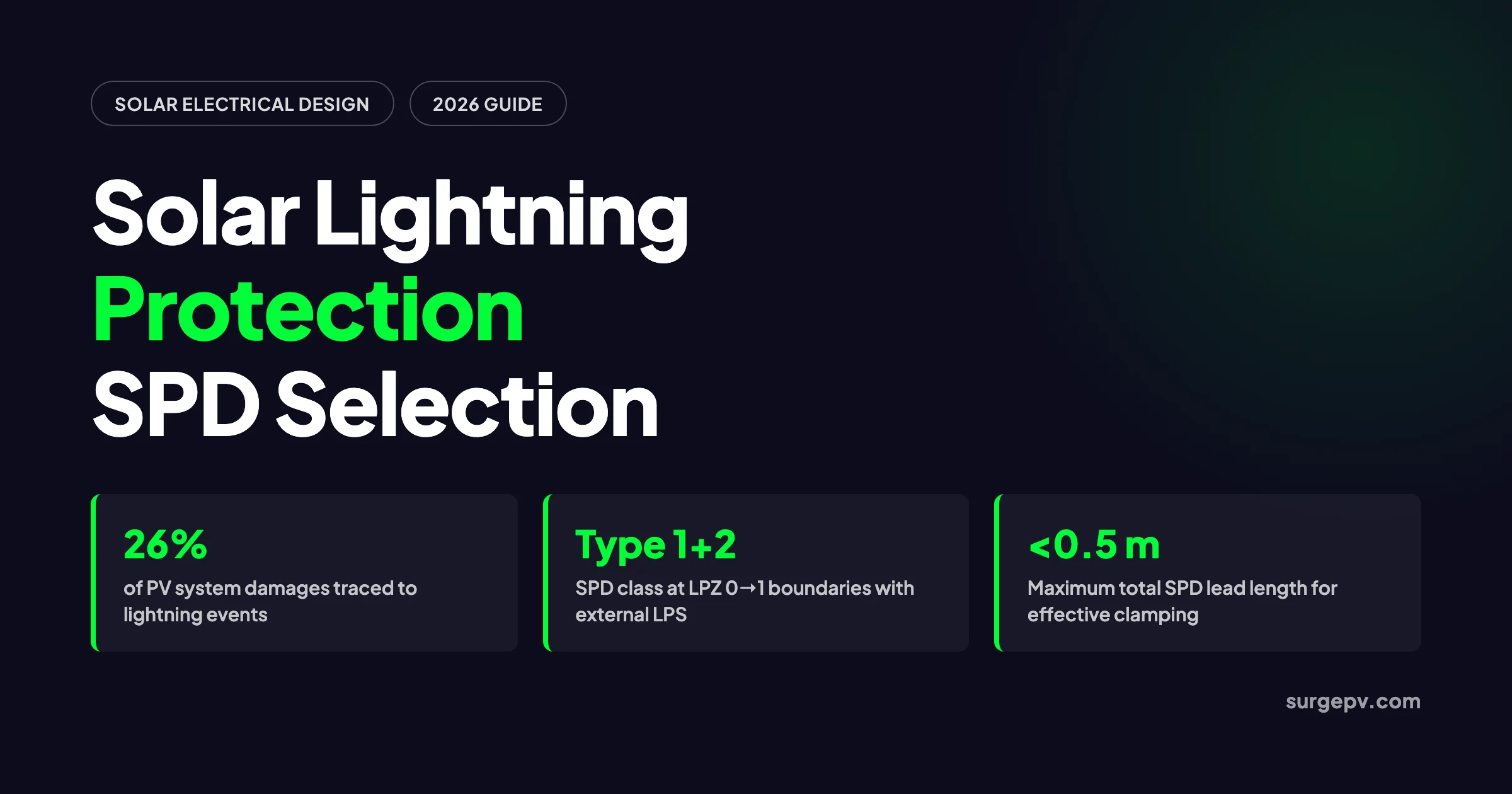
A single lightning event can destroy inverters, melt combiner boxes, and fracture module glass before the system owner finishes breakfast. The risk is not theoretical. Industry loss data compiled in 2019 found that lightning accounts for roughly 26% of PV system damage claims. The average insurance claim reaches $73,394 (PLOS ONE, 2019). Solar arrays make the problem worse: they are large, elevated, metal-rich, and connected to long cable runs that behave like antennas.
Effective solar lightning protection is not a single product. It is a coordinated system with two layers. The external layer intercepts direct strikes and safely dissipates their energy to earth. The internal layer clamps induced surges before they reach inverters, monitoring hardware, and switchgear. Most failures happen at the boundary between those layers — wrong SPD type, missing separation distance, shared earth pits, or leads that are too long.
This guide covers both layers for residential, commercial, and utility-scale solar. You will learn when an external lightning protection system (LPS) is mandatory. You will also learn how to select SPD types and ratings, where to place them, and which grounding mistakes create warranty claims.
Quick Answer
Solar lightning protection uses two coordinated layers: an external LPS to intercept direct strikes, and SPDs at DC combiner boxes, inverter inputs/outputs, and AC service entrances to clamp induced surges. Use Type 1+2 SPDs at LPZ 0→1 boundaries, Type 2 SPDs at inverter terminals, and keep leads under 0.5 m.
In this guide:
- Why solar arrays are lightning targets — and why most damage comes from indirect strikes
- The two-layer protection model: external LPS plus internal SPDs
- How IEC 62305-2 and NFPA 780 decide whether you need an external LPS
- External LPS components: air terminals, down conductors, earth electrodes
- SPD types for solar: Type 1, Type 2, and Type 1+2
- DC-side and AC-side SPD placement rules, including the 10 m cable rule
- Sizing SPDs: Uc, Imax, and Up with a worked example
- Grounding, bonding, and separation distance requirements
- Common installation mistakes that destroy inverters
- Inspection and maintenance schedules
Why Solar Arrays Are Lightning Targets
Solar arrays combine three features that increase lightning exposure: large horizontal metal area, elevation above surrounding structures, and long conductor runs. A rooftop array is often the highest conductive surface on the building. A ground-mount array is the highest object across a wide, flat field. Both are efficient collectors.
Direct strikes are dramatic but rare. A direct hit transfers 20–200 kA in microseconds. No SPD absorbs that. Only a properly designed external LPS with air terminals, down conductors, and a low-impedance earth termination can handle the direct-strike current path.
Indirect strikes cause most PV damage. When lightning hits the ground or a nearby structure, the resulting electromagnetic field induces thousands of volts onto the DC wiring between modules and the inverter. Long cable runs, large loop areas between positive and negative conductors, and poor shielding all amplify the induced voltage. PSCAD/EMTDC modeling showed that a 5 kA lightning strike with a 10/350 µs waveform could drive 500 A near the PV array. That current is enough to damage modules and inverters (MDPI Energies, 2017).
The damage pattern is consistent across claims: bypass diode failure, inverter input-stage damage, melted DC connectors, and fried monitoring equipment. The repair cost almost always exceeds the cost of proper protection by an order of magnitude.
| Threat Type | Source | Typical Current/Voltage | Primary Defense |
|---|---|---|---|
| Direct strike | Cloud-to-array or cloud-to-nearby structure | 20–200 kA, 10/350 µs waveform | External LPS (air terminals, down conductors, earthing) |
| Induced surge | Nearby strike electromagnetic field | 5–40 kA at equipment terminals, 8/20 µs waveform | Type 2 SPDs at inverter inputs/outputs and distribution boards |
| Ground potential rise | Strike current entering earth near system | kV-level local ground rise | Separate earth pits bonded at one point, low earth resistance |
| Grid surge | Utility switching or distant strike on grid | 1–10 kV transient | Type 2 AC SPD at service entrance and inverter AC output |
The Two-Layer Protection Model
Solar lightning protection only works when the external and internal layers are designed together. Treating SPDs as a substitute for an external LPS — or vice versa — is the most common design error.
Layer 1: External Lightning Protection System (LPS). Intercepts direct strikes, controls the current path down the structure, and dissipates energy into the earth. Governed by IEC 62305-3 (international) and NFPA 780 (United States).
Layer 2: Internal Surge Protection. Uses surge protection devices (SPDs) at zone boundaries to limit transient overvoltages on power and communication circuits. Governed by IEC 62305-4, IEC 61643-31 for DC PV SPDs, and NEC Article 285 / 230.67 in the United States.
The coordination concept comes from IEC 62305-4: lightning protection zones (LPZ). Each zone has a defined electromagnetic environment. At each boundary, you install protection appropriate to the threat.
- LPZ 0A: Direct exposure. Full lightning current and unattenuated field. This is the open air above the array.
- LPZ 0B: Protected against direct strikes by the LPS, but still exposed to the full electromagnetic field. This is the space under an air terminal protection zone.
- LPZ 1: Inside the building shield. Partial current and attenuated field. This is where DC cables enter the structure.
- LPZ 2+: Further attenuated zones inside the building, near sensitive equipment.
A Type 1 SPD goes at the LPZ 0→1 boundary. A Type 2 SPD goes at the LPZ 1→2 boundary. The energy is managed in stages rather than dumped on a single device.
When Lightning Protection Is Mandatory in 2026
The trigger for an external LPS is a risk assessment, not guesswork. IEC 62305-2 provides the formal method. NFPA 780 offers a prescriptive approach in the United States. Both start with local lightning ground flash density (Ng), measured in strikes per square kilometre per year.
Lightning density varies dramatically by region. Florida sees more than 14 flashes/km²/year in parts of the peninsula, while the contiguous United States averages about 2.0 flashes/km²/year (NOAA, 1994). In India, the eastern coast, central plateau, and northeast exceed 5 strikes/km²/year according to IMD data.
IEC 62305-2 calculates expected annual strike frequency to the structure and compares it against a tolerable risk threshold. If the calculated risk exceeds the threshold, the standard requires an external LPS. The assessment considers:
- Collection area of the structure and array
- Local ground flash density (Ng)
- Type of construction and roofing material
- Occupancy and consequence of damage
- Presence of sensitive electronic systems
For most residential systems below 10 kW in low-density regions, a full external LPS is often not required if the building already has adequate protection. For commercial and industrial systems, especially in high-density regions, an LPS is usually mandatory or strongly recommended by insurers.
In the United States, NFPA 780 is not automatically adopted everywhere. Many jurisdictions require it only for certain building categories or when the owner requests a certified LPS. However, insurance underwriters increasingly require NFPA 780-compliant systems for commercial solar.
For India-specific compliance, including IS 2309 and CEA 2023 SPD mandates, see the detailed guide from Heaven Green Energy.
External Lightning Protection System Components
An external LPS has four elements. Each must be designed as a continuous, low-impedance path.
Air Terminals
Air terminals intercept the descending lightning leader. Two common types are used in solar projects:
- Franklin rods: Simple vertical metal points, typically 16 mm diameter copper or stainless steel, installed 1 m above the highest point of the array. Protection radius is small — roughly 5–10 m depending on protection level.
- Early Streamer Emission (ESE) terminals: Active devices that emit an upward streamer earlier than a passive rod, giving a larger protection radius — 30–45 m. ESE systems follow NF C 17-102 and are common on large commercial and industrial rooftops.
For residential arrays, a single Franklin rod above the highest panel corner is usually sufficient. For commercial arrays, designers use a mesh of air terminals or one or more ESE terminals sized to cover the array footprint.
The rolling sphere method determines spacing. A sphere with radius corresponding to the protection level is rolled over the structure. Any point the sphere touches requires additional air terminal coverage.
| Protection Level | Rolling Sphere Radius | Typical Use |
|---|---|---|
| I | 20 m | Critical facilities, high-value assets |
| II | 30 m | Commercial solar 50–500 kW |
| III | 45 m | Standard commercial and residential |
| IV | 60 m | Low-risk structures |
Down Conductors
Down conductors carry strike current from the air terminal to the earth electrode. Rules from IEC 62305-3 and NFPA 780 are consistent:
- Keep them short and direct. Each 90° bend adds inductance equivalent to several feet of straight conductor.
- Use stranded conductors sized for impulse current: minimum 50 mm² copper or 80 mm² aluminum in IEC jurisdictions; 2 AWG copper minimum under NFPA 780.
- Provide at least two down conductors on opposite corners for commercial arrays.
- Install a test link 1 m above ground level for resistance testing.
- Joints should be welded or exothermically bonded, not simple bolted clamps.
Earth Termination
The earth termination dissipates strike current into the soil. IEC 62305-3 recommends each earth termination have a resistance not exceeding 10 Ω. In practice, aim for 5 Ω or less in high-risk areas.
A ring earth electrode around the structure is preferred over a single rod. Multiple vertical rods or a horizontal ring spreads current, reduces ground potential rise, and lowers overall system resistance. In rocky or high-resistivity soil, use ground enhancement material or electrolytic electrodes.
Equipotential Bonding
All metallic parts within 1 m of the LPS must bond to the equipotential bonding bar. This includes PV module frames, racking, cable trays, inverter enclosures, and AC equipment. Bonding prevents dangerous voltage differences during a strike. Jumpers are typically 6 mm² copper minimum.
SPD Types for Solar: Type 1, Type 2, and Type 1+2
SPDs are classified by the test waveform they can survive. The waveform matters because it determines which threat the device is built for.
Type 1 SPD
Type 1 SPDs are tested with the 10/350 µs waveform, which approximates actual lightning current. They can handle partial direct-strike current. Key parameter is Iimp, the lightning impulse current, typically 12.5–25 kA per pole.
Use Type 1 SPDs at LPZ 0→1 boundaries. These are points where cables enter a building with an external LPS, or where the array connects to an LPS and separation distance cannot be maintained.
Type 2 SPD
Type 2 SPDs are tested with the 8/20 µs waveform, which represents induced surges from nearby strikes and grid switching. They are the standard choice for inverter DC inputs, inverter AC outputs, and distribution boards. Key parameters are In (nominal discharge current) and Imax (maximum discharge current).
For residential systems, In ≥ 20 kA is typical. For commercial systems in moderate lightning zones, In ≥ 40 kA. Imax ratings of 40–65 kA are common.
Type 1+2 SPD
A Type 1+2 device combines both test capabilities in one housing. It is the practical choice when an external LPS exists but space is limited at the combiner box or service entrance. It also simplifies retrofit projects.
Type 3 SPD
Type 3 devices protect sensitive terminal equipment such as monitoring gateways, Wi-Fi routers, and RS-485 communication lines. They are not used on DC power circuits because PV voltages exceed their rating.
| SPD Type | Test Waveform | Threat | Typical Solar Location |
|---|---|---|---|
| Type 1 | 10/350 µs | Partial direct-strike current | LPZ 0→1 boundary, service entrance with LPS |
| Type 2 | 8/20 µs | Induced surges, grid switching | Inverter DC input, inverter AC output, distribution board |
| Type 1+2 | Both | Combined | Space-constrained combiner boxes, retrofits |
| Type 3 | 1.2/50 µs + 8/20 µs | Residual surges at sensitive equipment | Monitoring, communications lines |
SPD Placement Rules for DC and AC Sides
Placement is as important as device selection. An oversized SPD with 2 m of lead length can perform worse than a correctly sized SPD with 0.3 m leads.
DC-Side Placement
Array combiner box. Install a DC SPD at the combiner box output whenever the cable run from combiner to inverter exceeds 10 m. This is the widely used “10 m rule.” For systems with an external LPS, this SPD must be Type 1+2. For systems without an LPS in moderate-risk zones, Type 2 is sufficient.
Inverter DC input. Every grid-connected inverter should have an SPD at its DC input terminals. Install it within 0.5 m total lead length — measured along both the L+ and L− conductors from SPD terminals to the PE reference. Every additional 0.5 m of lead adds roughly 0.5–1 kV of effective clamping voltage due to inductance.
String-level protection. Large ground-mount EPC projects sometimes specify string-level SPDs for additional protection. This is not standard for residential or commercial rooftop systems.
AC-Side Placement
Inverter AC output. A Type 2 AC SPD belongs at the inverter AC output. For 230V single-phase systems, Uc ≥ 275V. For 400V three-phase systems, Uc ≥ 440V.
Main distribution board. If the solar sub-panel feeds into a main board at a different location, add a second Type 2 SPD there. Maintain 10 m of cable separation from the inverter AC SPD, or add a decoupling inductor.
Service entrance. NEC 230.67 (2020+) requires a Type 1 or Type 2 SPD at all new or replaced dwelling unit services. This is independent of the solar-specific SPD requirement.
Configuration Modes
The SPD configuration depends on the DC earthing system:
- Floating / IT system (most transformerless inverters in Europe): Use a 3-mode Y-configuration with L+ to PE, L− to PE, and L+ to L− protection.
- Functionally earthed negative rail (older US string inverters): Use 2-mode protection — L+ to PE and L− to PE.
- High-resistance earthed systems: Maintain SPD leakage resistance above 100 kΩ to avoid false insulation-monitoring alarms.
Pro Tip
Twist the L+ and L− SPD leads together to reduce loop inductance. If the inverter terminal block is far from the PE bus, run a short dedicated earth conductor to the nearest equipotential bonding point. Never route SPD earth leads through long conduit runs.
Sizing SPDs: Uc, Imax, and Up
Maximum Continuous Operating Voltage (Uc)
The most common sizing error is selecting Uc based on nominal operating voltage rather than the maximum open-circuit voltage at the coldest site temperature. Module Voc rises as temperature drops. A 900V string at 25°C can exceed 1,000V on a cold morning. An SPD rated at 1000V Uc will conduct continuously, overheat, and fail.
Use the IEC 61643-31 formula:
UcPV ≥ VOC(STC) × [1 + |αVoc| × (Tmin − 25°C)] × 1.1Where:
- VOC(STC) = module open-circuit voltage at STC × number of modules in series
- αVoc = temperature coefficient of Voc (use absolute value; typically 0.0028–0.0034 per °C for crystalline silicon)
- Tmin = minimum expected ambient temperature at the site
- 1.1 = IEC 61643-31 safety factor
Worked example:
- String: 20 modules, Voc(STC) per module = 41.5V
- String Voc(STC) = 20 × 41.5V = 830V
- αVoc = 0.0028/°C
- Tmin = −10°C
- VOC at −10°C = 830V × [1 + 0.0028 × (−10 − 25)] = 830V × 1.098 = 911.3V
- Apply safety factor: 911.3V × 1.1 = 1,002V → select 1200V SPD
Standard DC SPD ratings are 600V, 800V, 1000V, 1200V, and 1500V. Always round up to the next standard rating.
Discharge Current Rating (Imax)
Select Imax based on site lightning risk:
| Application | Lightning Risk | Recommended In | Recommended Imax |
|---|---|---|---|
| Residential rooftop, no LPS, Ng < 2.5 | Low | 20 kA | 40 kA |
| Commercial rooftop, moderate zone | Medium | 20–40 kA | 40–65 kA |
| Ground-mount, external LPS, Ng > 5 | High | 12.5 kA (Iimp) Type 1 | 40–65 kA Type 2 |
| Utility-scale, LPZ 0→1 boundary | Very High | 25 kA (Iimp) Type 1+2 | 40–65 kA |
Voltage Protection Level (Up)
Up is the clamping voltage the SPD presents to protected equipment during a surge. The IEC rule:
Up ≤ 0.8 × UwWhere Uw is the equipment impulse withstand voltage. Most string inverters have a DC input Uw of 4–6 kV, giving a target Up of 3.2–4.8 kV at the inverter terminals. Remember that lead length adds effective voltage; keep total lead length under 0.5 m.
Grounding, Bonding, and Separation Distance
Separate Earth Pits for LPS and Electrical Systems
Lightning protection earth and electrical equipment earth must be separate physical pits. Bond them at one point through the equipotential bonding bar. If they share a single pit, strike current raises the local ground potential. That current then backflows up the equipment grounding conductor — exactly the path you are trying to protect.
IEC 62305-3 and IS 2309 recommend physical separation of 5–10 m between lightning earth pits and electrical earth pits. The bonding conductor between them is typically 6 mm² copper minimum.
Separation Distance Between LPS and PV System
Separation distance prevents dangerous sparking between the external LPS and internal metallic installations. The formula from IEC 62305-3 is:
s = ki × (kc / km) × lWhere:
- ki depends on protection level (0.04 for Level I, 0.06 for Level III)
- kc depends on current distribution in down conductors (0.5–1.0)
- km depends on insulating material (1.0 for air, 0.5 for concrete)
- l is the length from the nearest equipotential bonding point
If the calculated separation distance cannot be maintained, bond the PV array frame and DC cabling to the LPS at the point of proximity, or install SPDs at that point.
Module Frame and Racking Bonding
All PV module frames, racking, and cable trays must bond to the equipotential bonding network. Bonding jumpers are typically 6 mm² copper. Use serrated washers and anti-oxidant compound on aluminum racking to maintain low contact resistance. See our glossary entry on equipment grounding for the fundamentals.
For a complete walkthrough of solar grounding system design, see our guide on solar PV grounding system design. For racking-specific bonding, see bonding and grounding solar racking.
Common Installation Mistakes
| Mistake | Consequence | Correct Practice |
|---|---|---|
| Using an AC SPD on the DC side | DC arc cannot self-extinguish; fire risk inside combiner | Use only IEC 61643-31-listed DC SPDs |
| Undersized Uc based on nominal voltage | SPD conducts continuously on cold mornings; thermal failure | Calculate temperature-corrected Voc max and apply ×1.1 |
| SPD lead length over 0.5 m | Effective clamping voltage rises; protection wasted | Keep L+ and L− leads to PE under 0.5 m total; twist them |
| Shared LPS and electrical earth pit | Strike current backflows into inverter ground | Separate pits, bonded at one point |
| Missing separation distance | Dangerous sparking between LPS and array frame | Maintain s, or bond and add SPDs at proximity |
| Single-pole SPD on floating DC | Ungrounded pole unprotected | Use 3-mode Y-configuration for IT/floating systems |
| No backup overcurrent protection | MOV short-circuit draws follow current | Coordinate SPD SCCR with upstream gPV fuse or DC MCB per overcurrent protection coordination |
| Ignoring SPD status after storms | Failed SPD remains in place; next surge destroys inverter | Inspect or replace after any confirmed lightning event |
The most expensive mistake is using an AC-rated SPD on the DC side. AC SPDs are not designed for DC arc extinction. When the MOV fails under DC fault current, the arc sustains and the enclosure can overheat and ignite.
How Solar Design Software Helps
Lightning protection design requires accurate data that is often guessed in the field: array geometry, cable run lengths, minimum site temperature, and protection zone boundaries. Cloud solar design software models these inputs before installation.
When you lay out the array and DC homeruns in a solar design tool, you can see immediately which combiner-to-inverter runs exceed 10 m. Those runs need SPDs at both ends. When you enter the minimum site temperature, the software outputs the temperature-corrected Voc max and the required SPD Uc rating. When you mark the building footprint and existing LPS, the tool flags separation-distance issues.
SurgePV’s solar proposals include the LPS and SPD specification in the client deliverable. This avoids the cost of retrofitting protection when an AHJ or insurer requests documentation at inspection. The generation and financial tool can model the avoided downtime and replacement cost of a properly protected system over 25 years.
Maintenance and Inspection Schedule
Lightning protection is not install-and-forget. SPDs degrade with every surge event, and earth resistance changes with soil moisture and corrosion.
| Task | Residential | Commercial | Utility-Scale |
|---|---|---|---|
| Visual SPD status check | Every 6 months | Monthly | Continuous via SCADA |
| Earth resistance test | Annually | Semi-annually | Annually |
| Retorque bonding connections | After year 1, then every 2 years | Annually | Annually |
| Inspect air terminals and down conductors | Every 2 years | Annually | Annually |
| Replace SPDs after confirmed strike | Immediately | Immediately | Immediately |
For commercial systems, specify SPDs with remote dry-contact status outputs and wire them into the SCADA or monitoring platform. This turns the silent open-circuit failure mode into an active alarm. Residential systems rely on visual status windows, so include the check in every maintenance visit.
Frequently Asked Questions
Do solar panels attract lightning?
Solar panels do not attract lightning more than other elevated metal structures, but arrays are vulnerable because they are large, exposed, and mounted above rooflines. They act as both a direct-strike target and an antenna that picks up electromagnetic surges from nearby strikes. Proper lightning protection uses an external LPS for direct strikes and SPDs for induced surges.
What is the difference between Type 1 and Type 2 SPD for solar?
Type 1 SPDs are tested with the 10/350 µs waveform and handle partial direct lightning current. They are required at LPZ 0→1 boundaries, such as where DC cables enter a building with an external LPS. Type 2 SPDs are tested with the 8/20 µs waveform and protect against induced surges from nearby strikes and grid switching. They go at inverter DC inputs, inverter AC outputs, and distribution boards.
Where should SPDs be placed in a solar PV system?
Install a DC SPD at the array combiner box when the cable run to the inverter exceeds 10 m. Always install a DC SPD at the inverter DC input within 0.5 m lead length. Install an AC SPD at the inverter AC output and at the service entrance or main distribution board. Systems with external LPS need Type 1+2 SPDs at LPZ 0→1 boundaries.
How do you size a solar SPD voltage rating?
Use the IEC 61643-31 formula: UcPV ≥ VOC(STC) × [1 + |αVoc| × (Tmin − 25°C)] × 1.1. Calculate the string open-circuit voltage at the coldest expected site temperature, apply the temperature coefficient from the module datasheet, then multiply by the 1.1 safety factor. Select the next standard rating: 600V, 800V, 1000V, 1200V, or 1500V DC.
Is a lightning protection system mandatory for solar installations?
In the United States, NFPA 780 governs external LPS and is triggered by risk assessment or insurance requirements. NEC 230.67 (2020+) requires SPDs at dwelling unit services. In IEC jurisdictions, IEC 62305-2 risk assessment determines whether an external LPS is required. India mandates IS 2309 / IEC 62305 compliance for rooftop solar above certain sizes. CEA’s 2023 grid code makes SPDs mandatory for grid-connected systems above 10 kW.
Can I use the same earth pit for lightning protection and equipment grounding?
No. Lightning protection earth and electrical equipment earth should be separate physical pits, ideally 5–10 m apart, bonded together at the equipotential bonding bar. Sharing a single pit allows strike current to raise the local ground potential and backflow into the electrical system, damaging inverters and creating step-potential hazards.
What is separation distance in lightning protection?
Separation distance is the minimum air or concrete clearance between the external LPS and internal metallic parts. It prevents dangerous sparking during a strike. The formula is s = ki × (kc / km) × l. If the required distance cannot be maintained, equipotential bonding or SPDs must be installed at the point of proximity.
How often should lightning protection and SPDs be inspected?
Inspect residential lightning protection and SPD status every 6 months. Inspect commercial systems monthly, or after any known lightning event. Check visual status windows, remote dry contacts if fitted, earth resistance annually, and retorque bonding connections after the first year. Replace SPDs after any confirmed nearby strike or when the status indicator shows failure.
Design Lightning-Protected Solar Systems in One Platform
SurgePV’s solar design software helps installers model array layouts, DC run lengths, and SPD requirements — so your protection specification is audit-ready from day one.
Book a DemoNo commitment required · 20 minutes · Live project walkthrough
Three actions before your next solar lightning protection design:
- Run the IEC 62305-2 risk assessment using the actual site ground flash density and array collection area. Do not rely on regional averages.
- Coordinate the external LPS and internal SPDs as one system. Specify Type 1+2 devices at LPZ 0→1 boundaries, Type 2 devices at inverter terminals, and keep every SPD lead under 0.5 m.
- Separate the lightning earth and electrical earth pits, bond them at one point, and document earth resistance at commissioning. Schedule SPD status checks on every maintenance visit.
For a deeper look at SPD standards and failure modes, read our guide on surge protection devices for solar PV.
Where this fits
This article is part of SurgePV's Solar Design hub, which works through the topic from first principles to the decisions a project team actually has to make.
