

Quick Answer
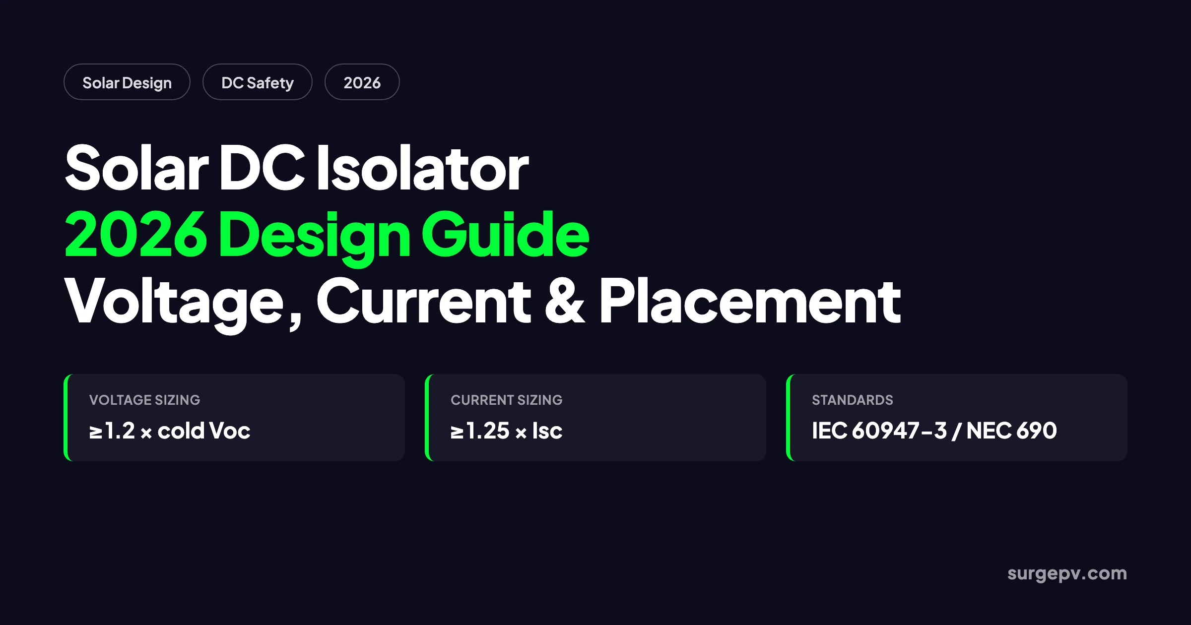
A solar DC isolator is a manually operated switch that creates a visible break between a PV array and the inverter or load. Size it for at least 1.2 times the cold-corrected open-circuit voltage and 1.25 times the short-circuit current, specify a DC-rated utilization category such as DC-PV1 or DC-PV2 under IEC 60947-3, and place it in a readily accessible, lockable location near the equipment it isolates.
The global solar fleet passed 2.2 terawatts of cumulative installed capacity by the end of 2024, according to the IEA Photovoltaic Power Systems Programme (2025). By end-2025, installed solar PV capacity reached 2,392 GW on an AC basis, according to IRENA Renewable Capacity Statistics 2026. Every one of those systems needs a safe way to separate the live DC conductors from the inverter, the battery, or the load. That device is the solar DC isolator.
Despite its simple appearance, the DC isolator is one of the most mis-specified components in solar design. Installers sometimes treat it as a commodity switch. Engineers sometimes copy ratings from old drawings. Inspectors regularly reject permit packages because the isolator voltage, current, or location does not match the code. This guide explains how to specify a solar DC isolator correctly in 2026.
In this guide:
- What a solar DC isolator is and what it is not
- Why DC-rated switchgear is non-negotiable
- Voltage, current, pole, and utilization-category sizing
- IEC, NEC, and UL standards that apply
- Load-break versus no-load and polarized versus non-polarized
- Placement rules for rooftop, ground-mount, and storage systems
- Common mistakes that cause field failures and rejected permits
- How SurgePV automates isolator sizing and single-line diagrams
Quick Answer
A solar DC isolator is a manually operated switch that creates a visible break between a PV array and the inverter or load. Size it for at least 1.2 times the cold-corrected open-circuit voltage and 1.25 times the short-circuit current, specify a DC-rated utilization category such as DC-PV1 or DC-PV2 under IEC 60947-3, and place it in a readily accessible, lockable location near the equipment it isolates.
What Is a Solar DC Isolator?
A solar DC isolator is a switch-disconnector that separates a photovoltaic array from the rest of the circuit. It is not a circuit breaker, a fuse, or a contactor. Its only job is to open the circuit under controlled conditions and keep it open until a qualified person decides to close it again.
When the handle is turned to the OFF position, the moving contacts pull away from the fixed contacts. The resulting air gap must be large enough to withstand the full system voltage without flashover. The gap must also be visible or otherwise verifiable, and the device must be capable of being locked in the open position. These three features, visibility, adequate gap, and lockability, are what make an isolator different from an ordinary switch.
In a typical string-inverter system, the DC isolator sits between the string combiner box and the inverter DC input. In a battery system, a second DC isolator sits between the battery bank and the inverter or charge controller. In larger plants, isolators appear at combiner boxes, recombiners, and inverter stations.
An isolator protects people, not conductors. It does not interrupt fault current. That job belongs to a fuse or a DC circuit breaker sized for the prospective short-circuit current.
SurgePV’s disconnect switch glossary covers the broader family of disconnects, including AC disconnects, utility disconnects, and rapid shutdown initiators.
Why DC Isolators Need DC-Specific Ratings
The most expensive mistake in DC isolator selection is substituting an AC-rated switch for a DC circuit. The ratings look similar on the nameplate, but the physics inside the device are entirely different.
The Arc Problem
Alternating current reverses direction 100 times per second in a 50 Hz system or 120 times per second in a 60 Hz system. Each reversal passes through zero voltage and zero current. When an AC switch opens, the arc that forms at the contacts is naturally extinguished at the next zero crossing. A small air gap is enough to prevent re-ignition.
Direct current has no zero crossing. When a DC switch opens under load, the arc persists as long as the voltage across the gap can sustain ionized air. The contacts must separate far enough and cool the arc fast enough to force the arc voltage above the supply voltage. Only then does the current stop. DC isolators use longer contact travel, arc chutes, ceramic splitter plates, and sometimes magnetic blowout coils to achieve this.
In documented field cases, AC-rated switches installed on DC solar strings have shown contact erosion, welding, and enclosure burn-through within months. The arc does not announce itself until the damage is done.
Voltage and Current Are Not Interchangeable
A switch marked 600 V AC is not a 600 V DC switch. A switch rated 32 A in an open panel may not carry 32 A inside a hot combiner box. Derating for temperature, enclosure, and duty cycle must be taken from the manufacturer’s DC tables, not from the AC headline number.
How to Size a Solar DC Isolator
Sizing starts with the string or array electrical parameters and ends with a standard device rating from a manufacturer datasheet. There are four numbers to check: voltage, current, poles, and utilization category.
Voltage Rating
The isolator must survive the highest voltage the array can produce. Module open-circuit voltage rises as temperature falls. Use the lowest expected ambient temperature for the site, not the nominal system voltage.
For IEC work, the rated operational voltage Ue must equal or exceed the corrected maximum Voc. For NEC work, the disconnect voltage rating must be at least 1.2 times the maximum system voltage at the lowest expected temperature.
Voltage sizing example:
| Parameter | Value |
|---|---|
| Module Voc at STC | 49.5 V |
| Modules per string | 28 |
| Uncorrected string Voc | 1,386 V |
| Temperature coefficient | -0.27 %/°C |
| Lowest expected temperature | -10 °C |
| Corrected string Voc | 1,555 V |
| NEC disconnect rating (× 1.2) | 1,866 V → select 2,000 V device |
A 1,500 V isolator would be undersized for this string. A 1,500 V inverter would also be the wrong choice. The correct design shortens the string or selects a 2,000 V inverter and isolator pair.
Current Rating
Current sizing follows similar conservatism. The isolator must carry the maximum current the array can deliver without overheating.
Under IEC 62548, a common rule is 1.25 times the string short-circuit current Isc. Under NEC 690.8, the maximum current is 1.25 × Isc, and the disconnect must be rated at 125 % of that value for continuous duty. The combined multiplier is 1.5625 × Isc.
Current sizing example:
| Parameter | Value |
|---|---|
| Module Isc | 12.3 A |
| Strings per MPPT input | 2 |
| Array Isc | 24.6 A |
| NEC continuous rating (× 1.5625) | 38.4 A → select 40 A or 50 A device |
Always round up to the next standard rating. Never install a 32 A isolator on a calculated 38 A circuit just because it is in stock.
Pole Configuration
A solar DC isolator normally disconnects both the positive and negative conductors at the same time. This is called a double-pole or 2P isolator. Disconnecting only one pole leaves the other conductor live and creates a shock hazard.
Some large central-inverter or tracker systems use four-pole isolators to switch multiple strings or both poles of a bipolar array. The pole count must match the circuit topology shown on the single-line diagram.
Utilization Category
IEC 60947-3 defines utilization categories that tell you what kind of load the switch was tested to interrupt. For PV, the relevant categories are:
- DC-20A / DC-21B: General DC switching of resistive or slightly inductive loads.
- DC-PV1: PV source-circuit switching under normal operating conditions.
- DC-PV2: PV source-circuit switching including more severe conditions such as reverse current or fault scenarios.
A switch marked only DC-21B may work in a simple string circuit, but a utility-scale project should specify DC-PV2 for the extra test coverage. North American listings use UL 98B for enclosed disconnect switches, UL 508i for industrial control equipment, or UL 489B for PV DC molded-case circuit breakers.
Standards and Certifications to Specify
Solar DC isolators sit at the intersection of product standards, system design standards, and installation codes. Knowing which document governs which question prevents arguments during plan review.
IEC Standards
- IEC 60947-3: The product standard for switches, disconnectors, switch-disconnectors, and fuse-combination units. It defines voltage ratings, utilization categories, dielectric tests, and endurance requirements.
- IEC 62548: The PV array design standard. It covers where isolators are needed, accessibility requirements, and coordination with overcurrent protection.
- IEC 60364-7-712: The low-voltage electrical installation standard for solar PV supply systems. It requires a means of isolation on the DC side and specifies that it must be clearly identified and accessible.
- IEC 60269-6: The standard for gPV fuses used with photovoltaic systems.
North American Codes and Listings
- NEC Article 690.13: Requires a PV system disconnecting means within sight of and capable of disconnecting all current-carrying conductors of the PV power source from all other conductors.
- NEC Article 690.15: Requires disconnects for specific equipment such as inverters, charge controllers, and batteries.
- NEC Article 690.12: Mandates rapid shutdown for PV systems on buildings, which affects where and how array-level isolation is achieved.
- UL 98B: Enclosed and dead-front switches for use in photovoltaic systems.
- UL 508i: Industrial control equipment for PV applications.
- UL 489B: Molded-case circuit breakers for DC PV applications.
- UL 1741-SA: Grid-support utility-interactive inverters and converters, relevant when the inverter integrates the disconnect function.
Regional Variations
Australia and New Zealand historically required rooftop DC isolators adjacent to the array. Many designs now use array-level DC isolators or rapid shutdown systems that meet AS/NZS 5033. The United Kingdom has moved away from mandatory rooftop isolators in favor of module-level shutdown or inverter-integrated switching under BS 7671 and MCS guidance. The United States emphasizes a readily accessible DC disconnect plus rapid shutdown under NEC 690.12.
Always confirm the edition of the code adopted locally and any amendments issued by the Authority Having Jurisdiction.
Load-Break vs No-Load and Polarized vs Non-Polarized
These two distinctions decide whether the isolator can be operated safely under normal current and whether it can be wired either way around.
Load-Break Isolators
A load-break DC isolator is rated to make and break the full operating current of the circuit. It can be opened during daylight while the array is producing. This is the default choice for the main PV array disconnect.
No-Load Isolators
A no-load isolator must only be opened after the current has been reduced to zero. It is common inside fused combiner boxes, where it isolates the fuse holders for servicing after the upstream DC breaker has opened. No-load isolators are smaller and cheaper, but they must carry a clear label such as “Do not disconnect under load.”
Using a no-load isolator as the main array disconnect is a field hazard. Contacts can weld closed, enclosures can overheat, and maintenance personnel can lose confidence in the isolation.
Polarized Isolators
A polarized DC isolator has designated positive and negative terminals. The internal arc quenching is optimized for current flow in one direction. Reversing the polarity can prevent proper interruption and lead to failure. Polarized isolators are cheaper but require careful wiring discipline.
Non-Polarized Isolators
A non-polarized isolator can interrupt current in either direction. This is valuable for strings that may be rewired, for maintenance where polarity labels have faded, or for systems where back-feed from parallel strings is possible. The tradeoff is a slightly larger mechanism and higher cost.
For rooftop and small commercial systems where multiple crews may work over 25 years, a non-polarized isolator reduces human-error risk.
Where to Place a DC Isolator in a PV System
Location is a code requirement, not just a convenience. The right place depends on which standard applies, what equipment is being isolated, and who needs to operate the switch.
General Placement Rules
- Within sight of the inverter, combiner box, or battery it isolates.
- Readily accessible without climbing, removing panels, or using special tools.
- Protected from direct rain, irrigation spray, and standing water unless rated for the exposure.
- Lockable in the open position with a provision for a padlock or lockout-tagout device.
- Clearly labeled with permanent, weather-resistant markings.
String Inverter Systems
The DC isolator is usually mounted on the inverter or in a disconnect box immediately beside it. The AC disconnect is separate and is placed between the inverter and the main panel. Some string inverters include a built-in DC disconnect. Verify that the integrated disconnect is listed for the application and that it can be locked open.
Combiner Boxes
In commercial and utility systems, each combiner box should have a DC isolator on the combined output. Some designs also include isolators on each string fuse holder. These are often no-load isolators for fuse servicing only. The combined output isolator must be load-break rated.
Battery Energy Storage Systems
Battery DC isolators must be rated for the maximum battery voltage and the maximum discharge current. Lithium-ion battery systems can deliver very high short-circuit currents, so coordination with the battery management system and DC fuse or breaker is critical. NEC 706 and IEC 62619 cover additional requirements for battery disconnects.
Rooftop DC Isolators
The industry has shifted away from rooftop DC isolators in many markets. They were originally installed to give firefighters a shutdown point at the array. Modern codes now rely on rapid shutdown devices, module-level power electronics, or inverter-integrated disconnects to achieve the same goal without adding roof penetrations and weather-exposed enclosures.
In a 2024 utility-scale PV inverter market report, Precedence Research (2025) noted that 1,500 V architectures accounted for 57 % of the utility-scale segment. Higher DC voltages make proper isolator placement and rating even more important. The energy available at a fault is larger, and the arc is harder to extinguish.
Common Installation Mistakes and Failure Modes
Most DC isolator failures are not caused by the device itself. They are caused by wrong ratings, wrong wiring, or wrong placement. Here are the patterns that show up in commissioning reports and inspection rejections.
Using an AC-Rated Switch on a DC Circuit
This remains the most dangerous mistake. The contacts and arc chutes are not designed for DC interruption. The device may appear to work for weeks or months until one hot-switching event destroys the contacts.
Ignoring Temperature-Corrected Voltage
Designers sometimes size the isolator for the nominal 1,000 V or 1,500 V system label. They forget that Voc rises in cold weather. An isolator rated at exactly 1,500 V can be overstressed on the first sub-zero morning.
Forgetting the Continuous-Duty Factor
NEC 690 requires the disconnect to be rated at 125 % of the maximum current for continuous operation. Skipping this factor produces an undersized device that overheats.
Mounting Too Close to Combustible Surfaces
DC isolators dissipate heat at the terminals. If the enclosure is mounted against a wooden wall or inside a cramped inverter compartment, thermal runaway can occur. Maintain the clearance specified by the manufacturer, usually at least 50 mm of free air around terminals.
Wrong Terminal Torque
Under-torqued terminals create high-resistance joints that heat up. Over-torqued terminals deform the contact surface and create the same problem. Use a calibrated torque driver and the value printed on the device.
Reversed Polarity on Polarized Isolators
Polarized isolators that are wired backward can fail to interrupt the arc. The result is contact damage, enclosure damage, or fire. Always verify polarity before energizing.
Mixing Isolation and Protection
An isolator is not a fuse. A fuse is not an isolator. Both are required in most PV source circuits. A fused disconnect can perform both functions only if it is listed for both overcurrent protection and safe isolation.
Designing DC Isolators with SurgePV
Manual isolator sizing is repetitive, and one transcription error can derail a permit. SurgePV automates the calculation and placement of DC isolators as part of the electrical design workflow.
When you build a project in SurgePV’s solar design software, the platform reads the module and inverter datasheets. It applies the temperature coefficients for the project location and calculates the corrected Voc and Isc. It then selects the disconnect rating against the active code library, whether NEC 690, IEC 62548, IS 16221, or AS/NZS 5033. The result appears automatically on the single-line diagram with the correct voltage, current, pole count, and label. For customer-facing documents, solar proposal software embeds the same diagram and equipment list into a branded proposal.
The string sizing calculator helps you check how many modules fit in a string before you pick the isolator voltage. The voltage drop calculator sizes the cable run between the array and the inverter. The wire size calculator matches conductor ampacity to the isolator and fuse ratings. Together, these tools remove the guesswork from DC circuit design.
For teams that need permit-ready drawings or PE-stamped plans, Heaven Designs provides detailed engineering and permit design support that works alongside SurgePV’s automated single-line diagrams. Installers can also use Clara AI to generate preliminary layouts and disconnect placements from satellite imagery before visiting the site.
Ready to automate DC isolator sizing?
Book a SurgePV demo to see how the platform sizes disconnects, generates code-compliant single-line diagrams, and exports permit packages in one workflow.
Next Steps
- Run the corrected Voc and Isc numbers for your next project and compare them against the isolator nameplate, not the system nominal voltage.
- Replace any AC-rated switches on DC solar circuits before the next maintenance cycle, and verify polarities on polarized isolators during commissioning.
- Add DC disconnect ratings and locations to your single-line diagram checklist so every permit package passes the first review.
FAQ
What is a solar DC isolator and why is it required?
A solar DC isolator is a manually operated switch that creates a visible, locked break between a PV array and the inverter or downstream circuit. It is required so technicians can verify a circuit is de-energized before maintenance. It also lets first responders shut down the DC side of a PV system safely.
How do you size a solar DC isolator?
Size the voltage rating at least 1.2 times the maximum open-circuit voltage at the lowest expected site temperature. Size the current rating at least 1.25 times the string or array short-circuit current, or 1.5625 times Isc under NEC continuous-duty rules. Always round up to the next standard device rating.
Can you use an AC isolator on a DC solar circuit?
No. AC isolators rely on current zero crossings to extinguish arcs, which occur 100–120 times per second in 50–60 Hz systems. DC current has no natural zero crossing, so an AC-rated switch can sustain an arc, overheat, and fail. Always use a DC-rated isolator listed for the system voltage and current.
What is the difference between a load-break and no-load DC isolator?
A load-break DC isolator is tested to open and close under full operating current without damage. A no-load isolator must only be opened after the circuit current has been reduced to zero by another device. Using a no-load isolator to interrupt live DC current is a known cause of contact welding and fire risk.
What standards govern solar DC isolators?
IEC 60947-3 governs the switch-disconnector itself, including DC utilization categories DC-PV1 and DC-PV2. IEC 62548 covers PV array design requirements, and IEC 60364-7-712 covers electrical installations for solar PV supply systems. In North America, NEC Article 690.13 and 690.15 define disconnecting means, while UL 98B, UL 508i, and UL 489B cover product listings.
Where should a DC isolator be installed in a PV system?
Install the DC isolator within sight and within 1 meter of the inverter or combiner box it isolates, in a readily accessible, weather-protected location. It must be lockable in the open position and clearly labeled. Rooftop DC isolators are no longer universally required where rapid shutdown devices and inverter-integrated disconnects meet local code.
What does non-polarized mean on a DC isolator?
A non-polarized DC isolator can interrupt current in either direction, so the positive and negative conductors can be connected without regard to terminal polarity. This is useful when strings may be wired either way or when reverse-current conditions are possible. Polarized isolators must be wired exactly as marked.
Does a DC isolator provide overcurrent protection?
No. A DC isolator provides isolation only, not overcurrent or short-circuit protection. Overcurrent protection in DC solar circuits requires gPV fuses compliant with IEC 60269-6 or UL 248-19, or DC circuit breakers listed for PV duty. Both protection and isolation devices must be present in a compliant design.
Where this fits
This article is part of SurgePV's Solar Design hub, which works through the topic from first principles to the decisions a project team actually has to make.


