A module becomes unavailable after a commercial rooftop design reaches internal review. The designer updates the array in AutoCAD, engineering revises the string plan in a spreadsheet, procurement changes a parts list, and sales edits the proposal. Each file now describes the same project, but nobody can prove that all 4 describe the same revision.
That is the real reason teams search for solar design software instead of AutoCAD. AutoCAD is a capable drafting platform. The purchase decision is whether it should remain the place where a solar team manually reconstructs project data and coordinates several disconnected outputs.
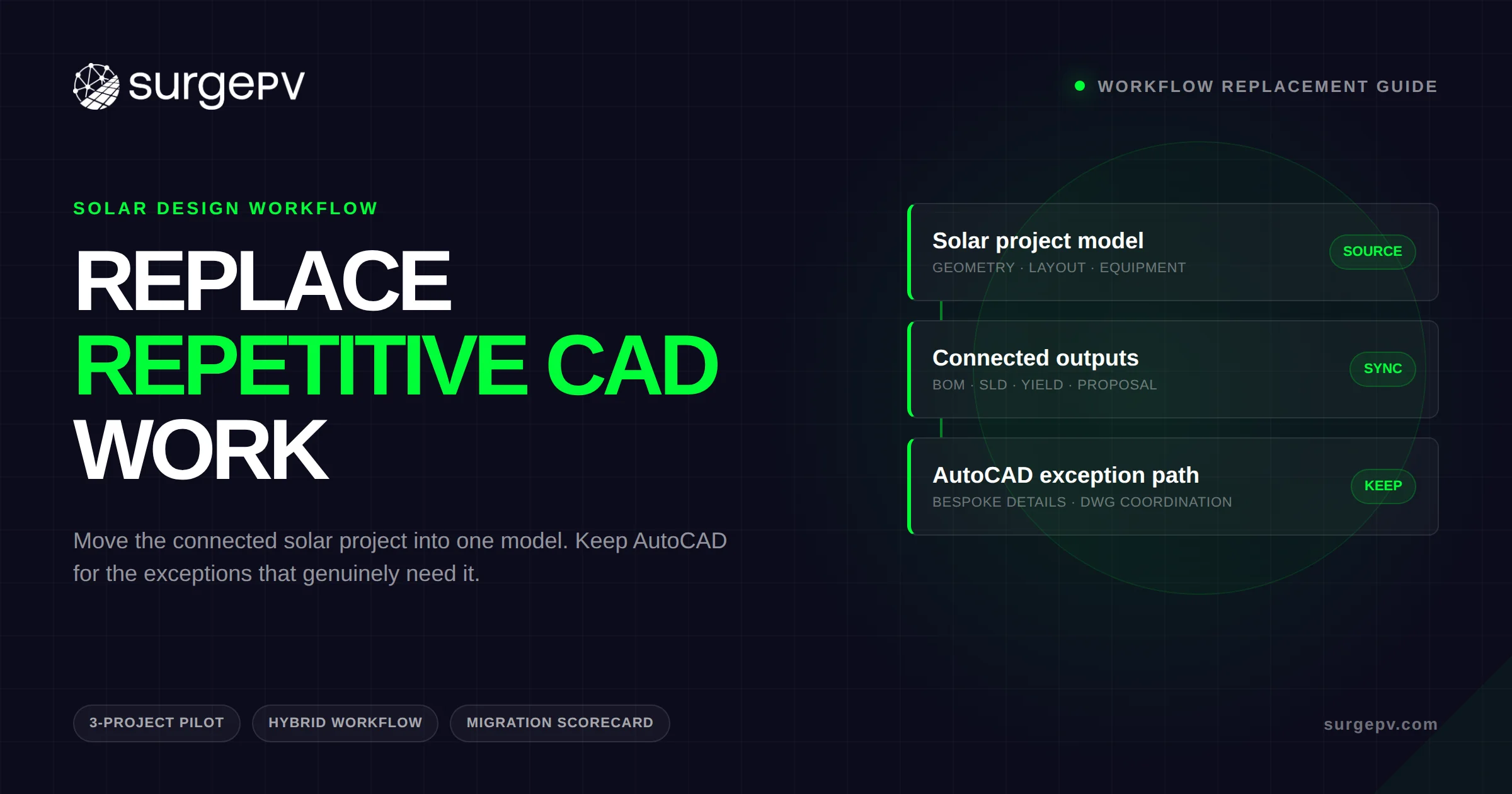
For many residential and commercial workflows, a solar-specific platform can own the repeatable design, simulation, electrical, financial, and proposal work. AutoCAD can remain available for bespoke details, downstream engineering coordination, or contractual DWG deliverables. The goal is to replace repetitive handoffs, not professional judgment.
TL;DR — Solar Design Software Instead of AutoCAD
Test the decision with 3 real projects: routine, revision-heavy, and exception-heavy. Autodesk documents powerful AutoCAD APIs, data extraction, and drawing comparison. A solar-specific platform adds configured PV behavior. The practical target is often solar-platform-first with CAD reserved for the deliverables that truly need it.
In this guide:
- Decide whether replacement, integration, or a CAD-primary model fits your team
- Compare AutoCAD and solar design software task by task
- Identify which solar work should move first and which should stay in CAD
- Map how one design change should flow through connected outputs
- Run a controlled 30-day migration pilot
- Calculate ROI from your own workflow data
- Test vendors with one of your existing AutoCAD projects
Can Solar Design Software Replace AutoCAD?
Solar design software can replace AutoCAD for many repeatable PV tasks, but it does not need to replace every drafting or engineering task to create value. The right boundary depends on project mix, contractual deliverables, the maturity of your CAD standards, and the share of projects that need custom details.
For preliminary residential and commercial design, the case for a solar-specific system is strong. Roof geometry, module placement, shading, energy production, string configuration, equipment quantities, financial scenarios, and proposal visuals all depend on the same project model. When one platform maintains those relationships, the team spends less time rebuilding the same information in different files.
Detailed construction documentation is different. A structural engineer may work within an established DWG library. A civil consultant may require a specific base file.
An owner may contractually require editable drawings. A local permitting process may depend on office-standard notes and details. These conditions can justify a CAD exception path even when a solar platform owns preliminary design.
The decision normally fits one of 3 operating models:
| Operating model | Solar platform owns | AutoCAD owns | Best fit |
|---|---|---|---|
| Solar platform first | Project model, layout, analysis, electrical configuration, quantities, financials, proposal | Bespoke details and selected exports | Teams with repeatable residential or commercial workflows |
| Connected hybrid | Solar model and calculated outputs | Defined drawing sheets, coordination, and custom documentation | EPCs with mixed standard and engineered deliverables |
| AutoCAD primary | Drawing model, blocks, schedules, and most documentation | Selected simulation or sales tasks | Teams whose custom engineering system already creates most value |
This framing prevents a false choice. A buyer does not need to prove that CAD is obsolete. The buyer needs to identify which system should be the source of truth for each project object and output.
A solar design software platform is a good replacement candidate when most work is repetitive, revisions are frequent, and design data must reach several downstream outputs. AutoCAD should remain primary when bespoke documentation dominates and the existing automation is reliable, documented, and maintained. Most teams will learn more from measuring their exception rate than from debating feature lists.
Why Solar Teams Outgrow a CAD-Heavy Workflow
CAD-heavy workflows usually develop gradually. A designer creates module blocks. An engineer builds a string-sizing workbook.
Sales maintains a proposal template. Procurement adds a material schedule. Each addition solves a local problem, but the full process becomes a chain of copies.
The weakness is not AutoCAD’s ability to draw. It is the number of boundaries where solar-domain data must be reinterpreted. A roof dimension becomes an array layout.
The layout becomes a module count. The module count and electrical characteristics become strings. Those strings affect equipment quantities, energy production, and the customer-facing offer.
One practitioner described using AutoCAD with self-built tools and templates for PV work in a solar design workflow discussion. Another AutoCAD user described entering solar project data in Excel, performing calculations there, and linking it back into the drawing in an AutoCAD template discussion.
These are individual accounts, not market-wide evidence. They still illustrate the exact handoffs a team should audit.
Consider a simple module substitution. The replacement module has different dimensions and electrical characteristics. A CAD block may change, but the array fit, row spacing, quantity, string voltage, inverter match, BOM, SLD, yield model, price, and proposal may also need review.
The risk rises when each output has a different owner and update method.
Custom automation can reduce that work. Autodesk supports AutoLISP, .NET, ObjectARX, ActiveX, and cloud automation interfaces through its AutoCAD API and Automation APIs. A skilled team can create commands, process drawings, update title blocks, and automate documentation.
That capability has a cost profile of its own. Someone must design the standards, maintain code and blocks, test updates, train users, and repair links when equipment or templates change. The relevant comparison is not AutoCAD has no automation versus solar software has automation.
It is our maintained custom system versus configured solar-domain behavior in a supported platform.
Audit the workflow by following one piece of data, such as module model, from intake to proposal. Count how many times it is typed, copied, transformed, checked, and approved. Then repeat the exercise for roof dimensions, inverter selection, string allocation, annual yield, and project price.
That map exposes the real switching case.
AutoCAD vs Solar Design Software: Task-by-Task
The two tool categories overlap, but they begin with different assumptions. AutoCAD provides a general drafting and automation environment. Solar design software begins with PV objects, calculations, and outputs.
A fair evaluation should compare the work required to reach an approved deliverable, not whether both tools can display a rectangle.
| Task | AutoCAD approach | Solar-specific approach | Practical decision |
|---|---|---|---|
| Roof and site geometry | Draw, import, or develop custom standards | Model the roof or site within a PV workflow | Move when setup is repetitive |
| Module placement | Blocks, arrays, scripts, or add-ins | Automatic and manual PV module placement | Move when options and substitutions are frequent |
| Obstructions and shading | Geometry plus separate analysis or custom process | Physics-based irradiance and obstruction analysis | Move when yield depends on near shading |
| Energy production | Usually external software or custom calculation | Simulation tied to the current design | Move when proposal yield must follow revisions |
| String and inverter configuration | Blocks, annotations, spreadsheets, or custom logic | PV-specific sizing and configuration | Move after electrical validation |
| Bill of materials | Attributed blocks, data extraction, spreadsheets | BOM generated from design objects | Move when stale quantities cause rework |
| Single-line diagram | Manual drafting, templates, or scripts | SLD generated from electrical configuration | Move for standard cases; retain detail exceptions |
| Financial analysis | External workbook | Yield, CAPEX, payback, IRR, and NPV in one workspace | Move when sales rebuilds scenarios often |
| Customer proposal | External document or publishing tool | Branded proposal linked to project outputs | Move when revisions reach customers slowly |
| Bespoke details | Strong general-purpose drafting control | May be outside the intended scope | Keep in CAD where needed |
| DWG coordination | Native working format and mature collaboration | Export path must be tested | Integrate when downstream parties require DWG |
AutoCAD can produce useful data from disciplined drawings. Autodesk’s Data Extraction Wizard documentation explains how users can select objects and properties, refine extracted information, combine it with external data, and output it to a table or file.
Autodesk also documents extracting block attributes. With consistent attributed blocks, a team can produce schedules or BOM-like exports.
AutoCAD also supports document control functions. Its drawing comparison can show modified, added, and removed objects. The Sheet Set Manager organizes sheets and supports publishing workflows.
These functions matter because they prevent an unfair comparison. AutoCAD can manage data, revisions, and publishing. The question is how much solar-specific configuration sits between a blank or office-standard drawing and the finished project workflow.
In SurgePV, the safe product comparison is narrower. The live workflow includes 3D rooftop modeling, automatic and manual module placement, string sizing, BOM and SLD generation, solar shadow analysis software, production simulation, financial metrics, and branded proposals. It runs in a browser.
It does not replace licensed engineering judgment, structural calculations, every permit package, a CRM, or lossless round-trip DWG editing.
The best evaluation row is revision propagation. Change a module, obstruction, layout, string, or commercial assumption. Then observe which dependent outputs update, which are flagged, and which still require manual action.
A long feature list cannot substitute for that test.
What to Move Out of AutoCAD First
Start with work that is frequent, repeatable, and derived from the same solar project data. Do not begin with the strangest detail your engineering team has produced. An exception-first evaluation makes any specialized platform look weak and reveals little about daily capacity.
Preliminary roof modeling is a common starting point. If designers repeatedly reconstruct roof planes, ridges, obstructions, and usable zones before placing modules, a solar-specific model can reduce setup work. The team should still verify dimensions, imagery, obstructions, access rules, and site conditions under its normal QA process.
Module-layout options are another strong candidate. Sales may ask for a maximum-capacity version, an appearance-led version, and a lower-cost option. In a CAD-heavy process, each layout can trigger manual recounting and spreadsheet edits.
In a connected model, the layout remains the source for quantities and related analysis.
Move shading and production analysis with the geometry when possible. Separating layout from irradiance creates another handoff and another chance to simulate the wrong revision. SurgePV’s shadow and irradiance workflow and solar financial analysis tool are live capabilities that can be evaluated together with the current design.
Standard string configuration, BOM, and SLD outputs should follow after the team validates equipment data and electrical assumptions. These are high-value tasks because a layout or module change can affect all 3. Our guides to automating a solar bill of materials and automating solar single-line diagrams cover the control steps in detail.
Finally, connect the proposal. A customer should not receive an older module count, yield estimate, price, or array image because the design changed after sales exported a PDF. Solar proposal software is most useful when it consumes the approved project inputs rather than acting as an isolated document editor.
Use this migration order:
- Preliminary geometry and reusable site objects
- Module placement and option development
- Shading and production analysis
- String and inverter configuration for standard cases
- Design-derived BOM and SLD outputs
- Financial scenarios and branded proposals
- Selected exports to CAD for the defined exception path
The order can change, but the principle should not. Move a connected chain, not a single task that leaves every adjacent handoff intact.
When AutoCAD Should Stay in the Solar Workflow
AutoCAD should stay when it is the most reliable place to create or coordinate a required deliverable. A credible replacement plan names those cases before rollout and gives them an owner.
Bespoke construction details are the clearest example. A commercial rooftop may need custom equipment pads, unusual roof-penetration details, structural reinforcement notes, or a drawing convention required by an engineer of record. These tasks benefit from general drafting control and established office libraries.
Structural and civil documentation may also remain in CAD. Solar design software can supply array geometry and equipment information, but it should not be presented as an automatic substitute for qualified structural analysis, civil grading, drainage work, or professional approval. The project team must preserve the review gates required by its contract and jurisdiction.
Coordination requirements can decide the tool boundary. Architects, general contractors, owners, and consultants may exchange DWG files under a documented process. If the editable drawing is a contractual source file, an exported PDF is not enough.
The buyer should test the exact DXF or DWG handoff, including units, coordinate reference, layers, blocks, text, line types, and revision ownership.
Existing custom automation may justify a CAD-primary model. A team that has maintained blocks, scripts, extraction templates, and quality controls for years may already possess a working solar system inside AutoCAD. Replacing it only makes sense if the new route reduces total work or risk after migration, training, and exceptions are included.
Keep AutoCAD for these conditions:
- The deliverable requires bespoke drawing control
- A licensed engineer’s workflow depends on established DWG libraries
- Civil, structural, or architectural coordination is central to the project
- The contract names DWG as the editable source deliverable
- Existing automation covers the project mix and has a clear maintainer
- Exceptions form a large share of real project work
The boundary must be explicit. If a layout changes in the solar platform after a CAD detail is issued, which system holds the approved geometry? Who updates the other file?
What identifier links the two revisions? A hybrid process without these answers can create more confusion than the old process.
Choose a Replacement, Hybrid, or CAD-Primary Model
Choose the operating model from evidence about your projects. A replacement decision based only on license count or demo speed ignores the cost of exception handling. A CAD-primary decision based only on familiarity ignores the cost of repeat work.
| Decision factor | Solar platform first | Connected hybrid | AutoCAD primary |
|---|---|---|---|
| Standard projects as share of work | High | Mixed | Low |
| Revision frequency | High | Medium to high | Low or well automated |
| Customer proposals tied to design | Frequent | Frequent | Limited |
| Bespoke details | Rare | Regular but bounded | Dominant |
| Contractual DWG requirement | Occasional | Common | Central |
| Maintained CAD automation | Limited | Useful in selected tasks | Extensive and reliable |
| Cross-team data handoffs | Many | Several | Controlled within CAD system |
| Preferred source of truth | Solar project model | Defined by object and deliverable | Drawing model |
Use replace for tasks where the solar platform can own the object and its dependent outputs. Use integrate where another discipline or deliverable still needs CAD. Use keep where CAD provides unique control that the platform does not claim.
Then estimate the exception rate. Review a representative project sample and mark every task that required custom drafting, external coordination, or post-export cleanup. Do not use memory alone.
Project records often show that a supposedly rare exception is routine, or that a feared edge case appears only once.
Training also changes the answer. A solar platform may reduce CAD skill requirements for preliminary work, but users still need design knowledge. They must understand geometry, equipment limits, electrical configuration, shading assumptions, yield inputs, and commercial outputs.
Easier interaction does not make a poor assumption correct.
Data ownership belongs in the scorecard. Confirm export formats, project retention, access controls, naming, version identifiers, and what happens if the team ends a subscription. For a hybrid model, define which system owns geometry, electrical configuration, financial inputs, and final drawing status.
Compare One AutoCAD Project With SurgePV
Bring an existing rooftop project, its spreadsheet handoffs, and a known revision. We will compare the solar-platform-first workflow and identify exactly where your CAD exception path should remain.
Book a DemoNo commitment required · 20 minutes · Live project walkthrough
How a Connected Solar Model Changes Revisions
A connected model does not make revisions disappear. It changes the way their impact is discovered and controlled. The model holds relationships that a file-based workflow often asks people to remember.
Imagine replacing a 550 W module with a different model. In the old process, the designer may insert a new block or alter dimensions. Engineering checks voltage and current in a workbook.
Procurement edits descriptions and quantities. Sales changes capacity, energy, and pricing. Every handoff has its own version and approval state.
In a connected solar workflow, the replacement starts with the equipment definition in the project. The designer reassesses fit and module count. Electrical configuration is recalculated or flagged for review.
BOM and SLD outputs are regenerated from the current design. Production and financial assumptions are rerun. The proposal is published only after approval.
| Revision impact | CAD-heavy file chain | Connected project model |
|---|---|---|
| Geometry | Update blocks and dimensions | Update module object and layout |
| Electrical | Open and revise workbook or drawing | Reconfigure or review strings and inverter |
| Materials | Recount or edit schedule | Regenerate design-derived BOM |
| SLD | Edit symbols, ratings, and labels | Regenerate, then review output |
| Energy | Transfer current layout to simulator | Rerun from current design |
| Financials | Replace yield and equipment inputs | Recalculate in the same workspace |
| Proposal | Replace images, values, and text | Regenerate from approved project data |
This does not mean every output is automatically approved. Automation can propagate a bad equipment choice as consistently as a good one. The team still needs checks for geometry, equipment status, voltage and current limits, inverter loading, shading inputs, loss assumptions, material completeness, prices, and customer claims.
Set project states such as draft, technical review, commercial review, approved, issued, and superseded. The exact labels are less important than the rule that only an approved state can feed a customer or procurement output.
SurgePV’s solar designing workflow connects 3D design, module layout, string sizing, BOM, and SLD generation. Its production, financial, and proposal functions extend that chain. During evaluation, ask which values update automatically, which are flagged, and which require a deliberate rerun or approval.
Clear limits are more useful than a claim that everything happens automatically.
Run a 30-Day Migration Pilot
A controlled pilot answers the replacement question without forcing a company-wide cutover. Use a small team, known projects, and agreed acceptance criteria. Keep the old process available until the comparison is complete.
Week 1: Map the Current State
Document the workflow from site information to issued proposal or engineering handoff. Record each system, file, owner, approval, duplicate field, and revision touchpoint. Time active work where possible, but separate waiting time from labor.
Select 3 projects. The first should be routine. The second should have frequent layout or equipment changes.
The third should contain a known exception, such as bespoke detailing or a required DWG coordination step.
Label every output platform, CAD, or shared/export. This first version is a hypothesis, not a final policy. It gives the pilot a boundary to test.
Week 2: Configure and Rebuild
Set equipment, design assumptions, naming rules, financial inputs, proposal branding, and user responsibilities. Rebuild the selected projects without copying conclusions from the old outputs.
Compare roof geometry, module positions, quantity, array capacity, string configuration, inverter choice, shading, production, and financial assumptions. A difference is not automatically an error. Trace it to imagery, equipment data, loss settings, calculation method, or an old manual assumption.
Test the DXF or DWG export on the exception project. Open it in the real downstream environment and inspect scale, units, layers, geometry, coordinates, and editability. A file extension alone does not prove that the handoff works.
Week 3: Force Revisions
Change the module, remove a roof zone, add an obstruction, alter the inverter, and revise a commercial input. Record every output that updates, every warning, and every manual action.
Ask another team member to take over the project from the documented state. This exposes hidden knowledge in custom blocks, folder names, workbooks, and personal habits. A process that works only for the pilot owner is not ready to scale.
Week 4: Decide and Document
Score both workflows against the same criteria. Include active labor, revision effort, duplicated entry, defect detection, output quality, training, administration, export cleanup, and exception handling.
Define the source of truth for geometry, equipment, electrical configuration, quantities, production, financials, proposal, and final drawings. Set approval gates and naming rules. Document the CAD exception path with an owner and revision link.
Use these exit criteria:
- All 3 projects reach an agreed comparable output
- Differences are explained and accepted, not ignored
- At least 1 meaningful revision has passed through each workflow
- The DWG or DXF handoff works for the real downstream user
- QA owners can identify what they must review
- Training needs and remaining seats are known
- The chosen source-of-truth rule is written
If the pilot fails an exit criterion, do not hide it inside an average score. Decide whether configuration, training, product limits, or the operating model caused the failure.
Calculate the ROI With Your Own Workflow Data
The ROI case should begin with observed work, not a vendor benchmark. Measure a representative project sample and keep the assumptions editable.
Use this baseline formula:
monthly workflow cost = projects × (CAD drafting hours + data-transfer hours + revision hours) × loaded hourly rate + software and administration cost
Then model the benefit:
monthly benefit = avoided labor cost + avoided outsourced preliminary-design cost + avoided duplicate-tool cost + value of recovered capacity
Calculate payback:
payback months = implementation cost ÷ monthly net benefit
Do not count the same hour twice. If a designer’s saved time is redeployed to more projects, it is capacity, not an immediate payroll saving. If headcount or outsourcing spend is actually reduced, the saving can be treated as cash impact.
State which case you are using.
Here is a hypothetical example for method only. It is not an industry benchmark.
| Input | Hypothetical value |
|---|---|
| Projects per month | 20 |
| CAD drafting and transfer time per project | 3.0 hours |
| Average revision time per project | 1.0 hour |
| Loaded labor rate | $55 per hour |
| Current software and administration | $1,200 per month |
| New recurring workflow cost | $1,600 per month |
| Implementation and training cost | $8,000 |
| Hours retained after migration | 1.5 hours per project |
The current monthly labor component is 20 × 4.0 × $55, or $4,400. Adding the illustrative administration amount produces $5,600. The new labor component is 20 × 1.5 × $55, or $1,650.
Adding the illustrative recurring cost produces $3,250.
The modeled difference is $2,350 per month. If those hours become a real avoided cost, the simple implementation payback is about 3.4 months. If the team redeploys them, report 50 recovered hours per month and model the extra contribution from projects completed with that capacity.
Do not call the full $2,350 a saving as well.
Include costs that optimistic models omit: onboarding, template configuration, QA overlap, export cleanup, retained AutoCAD seats, internal support, and the slower first projects. Run a sensitivity table with low, expected, and high adoption. The business case should survive an ordinary month, not only the cleanest demo project.
Test Vendors With a Real AutoCAD Project
A generic product tour shows the vendor’s ideal path. A buying test should show your path, including the part that usually breaks.
Bring the original site inputs, AutoCAD files, calculation workbooks, equipment requirements, proposal, and final outputs. Choose a project the team understands well enough to spot a questionable assumption. Remove confidential customer data if needed, but preserve the technical complexity.
Ask the vendor to complete this test:
- Build or import the roof and site geometry
- Place modules manually and automatically where available
- Add representative obstructions and run shading analysis
- Configure strings and the inverter
- Generate the BOM and SLD
- Run production and financial scenarios
- Produce a branded proposal
- Replace the module and show every affected output
- Export the required DXF or DWG data
- Explain all manual checks, unsupported tasks, and roadmap dependencies
Score the result on evidence:
| Criterion | What to verify |
|---|---|
| Geometry | Accuracy, edit control, units, and handling of complex roofs |
| Equipment | Database coverage, editable properties, and version awareness |
| Electrical | Assumptions, warnings, override process, and review output |
| Shading and yield | Inputs, loss visibility, rerun behavior, and reporting |
| BOM and SLD | Relationship to the current design and revision identification |
| Financials | Transparent assumptions, scenario control, and output consistency |
| Proposal | Branding, approved values, visuals, and revision traceability |
| CAD handoff | DXF or DWG geometry, layers, units, and downstream usability |
| Administration | Roles, naming, project states, exports, and data retention |
| Exceptions | Clear fallback without duplicating the whole project |
Ask what is live today. Native CRM, headless proposal APIs, and a mobile field-capture app are not live SurgePV capabilities and should not be implied during comparison. The current platform covers browser-based design, shadow analysis, production and financial work, proposals, and Clara AI for design and proposal copy.
The final question is simple: can your team complete the common path with fewer handoffs while preserving a safe route for the uncommon path? If the vendor cannot show both, the operating model is incomplete.
Conclusion: Replace Repetition, Keep the Exception Path
Solar design software does not need to eliminate AutoCAD to improve a solar company’s design capacity. It needs to own the repeatable project model and keep connected outputs aligned when the design changes.
Start with 3 actions:
- Map one project end to end. Count duplicate fields, tools, owners, approvals, and revision touchpoints.
- Run a 3-project pilot. Include a routine project, a revision-heavy project, and an exception case with a real CAD handoff.
- Write the source-of-truth rule. Assign ownership for geometry, electrical configuration, quantities, simulation, financials, proposals, and final drawings.
The likely answer for many installers and EPCs is solar-platform-first, CAD by exception. The solar software handles repeatable design, analysis, electrical, financial, and proposal work. AutoCAD remains where bespoke drafting or contractual coordination requires it.
That boundary can evolve. A team may begin by moving preliminary layouts and proposals, then add electrical and design-derived outputs after validation. Another team may keep a stable hybrid indefinitely because its engineering partners depend on DWG.
Both outcomes are valid when ownership is clear and measured results support the decision.
Review the model after the pilot and again after the first production batch. Compare the projected time with actual work. Count the exceptions that reached CAD, the cleanup they needed, and the revisions that crossed the system boundary.
If the exception rate is higher than expected, refine the boundary before adding more users.
Protect the fallback during rollout. Retain the templates, licenses, trained people, and file access needed to finish active projects. Set a date and acceptance test for retiring any redundant tool.
A controlled retirement is safer than leaving an unofficial spreadsheet or drawing path alive forever.
The strongest outcome is not zero CAD. It is a documented workflow in which the common solar project moves quickly, every approved output refers to the current design, and unusual engineering work has an intentional route. That is a more useful standard than replacing one application logo with another.
Do not buy from a slide deck. Bring one of your current AutoCAD projects to a SurgePV demo, force a real revision, and compare the outputs with your existing process. The result will show which work can move now and which CAD path should remain.
Frequently Asked Questions
Can solar design software fully replace AutoCAD?
Solar design software can replace AutoCAD for many repeatable PV tasks, including roof modeling, module layout, string configuration, shading, yield, BOM, SLD, financial analysis, and proposals. It may not replace every bespoke drawing, structural or civil coordination task, office-standard sheet, or contractual DWG deliverable.
Define replacement by workflow, not application count. If a solar platform owns the common project path and AutoCAD handles 1 bounded exception, the team has still replaced a CAD-heavy process.
Can I export a SurgePV solar design to DWG or DXF?
SurgePV supports exporting roof and layout data to DXF or DWG for AutoCAD and similar tools. Buyers should verify the required layers, units, geometry, annotations, coordinate handling, and downstream editing process with one of their own projects.
Do not assume that any export creates a lossless round trip. Decide which system owns the geometry after export and how later revisions will be coordinated.
Should commercial solar EPCs keep AutoCAD?
Many commercial solar EPCs should keep an AutoCAD exception path. Architects, engineers, owners, or permitting teams may require editable DWG files, detailed construction sheets, or office-standard libraries.
The better question is whether AutoCAD should remain the primary solar model. A connected hybrid can let the solar platform own layout, simulation, electrical configuration, quantities, financials, and proposals while CAD owns selected construction documentation.
What solar tasks should be migrated out of AutoCAD first?
Start with frequent tasks that use the same project data: preliminary roof modeling, module placement, shading, production estimates, string sizing, BOM and SLD generation, financial scenarios, and proposals. Moving these together removes more handoffs than moving a single isolated task.
Keep rare custom details in CAD during the pilot. Their exception rate and cleanup cost will show whether they should stay there.
How do we compare solar software with our custom AutoCAD templates?
Run the same 3 representative projects through both workflows. Score setup, revisions, duplicate entry, output quality, defect detection, training, export quality, and exception handling.
Include the time required to maintain blocks, scripts, extraction templates, spreadsheet links, and documentation in the AutoCAD baseline. Custom automation is valuable, but it is not free to own.
Will switching from AutoCAD eliminate solar design QA?
No. Automation changes the objects and calculations that reviewers inspect, but it does not remove engineering judgment or approval responsibility.
Define who reviews geometry, equipment data, electrical configuration, shading inputs, yield assumptions, financial inputs, materials, and exported files. Automation should make changes traceable and checks repeatable.
How should we calculate the ROI of replacing an AutoCAD-heavy workflow?
Measure drafting, data-transfer, revision, administration, outsourcing, and software costs across a representative sample. Compare that baseline with implementation cost and the new recurring workflow cost.
Count either avoided labor cost or the value of redeployed capacity. If you count both for the same hours, the ROI is overstated. Include training, parallel QA, export cleanup, and remaining AutoCAD seats.
What should I bring to a solar design software demo?
Bring a routine project, a revision-heavy project, and a known exception case. Include original site data, equipment requirements, AutoCAD files, calculation spreadsheets, proposal, and expected deliverables.
Ask the vendor to complete one meaningful change and show how it reaches the layout, stringing, BOM, SLD, energy model, financials, proposal, and export. That test reveals more than a standard feature tour.
Where this fits
This article is part of SurgePV's Solar Design hub, which works through the topic from first principles to the decisions a project team actually has to make.