Quick Answer
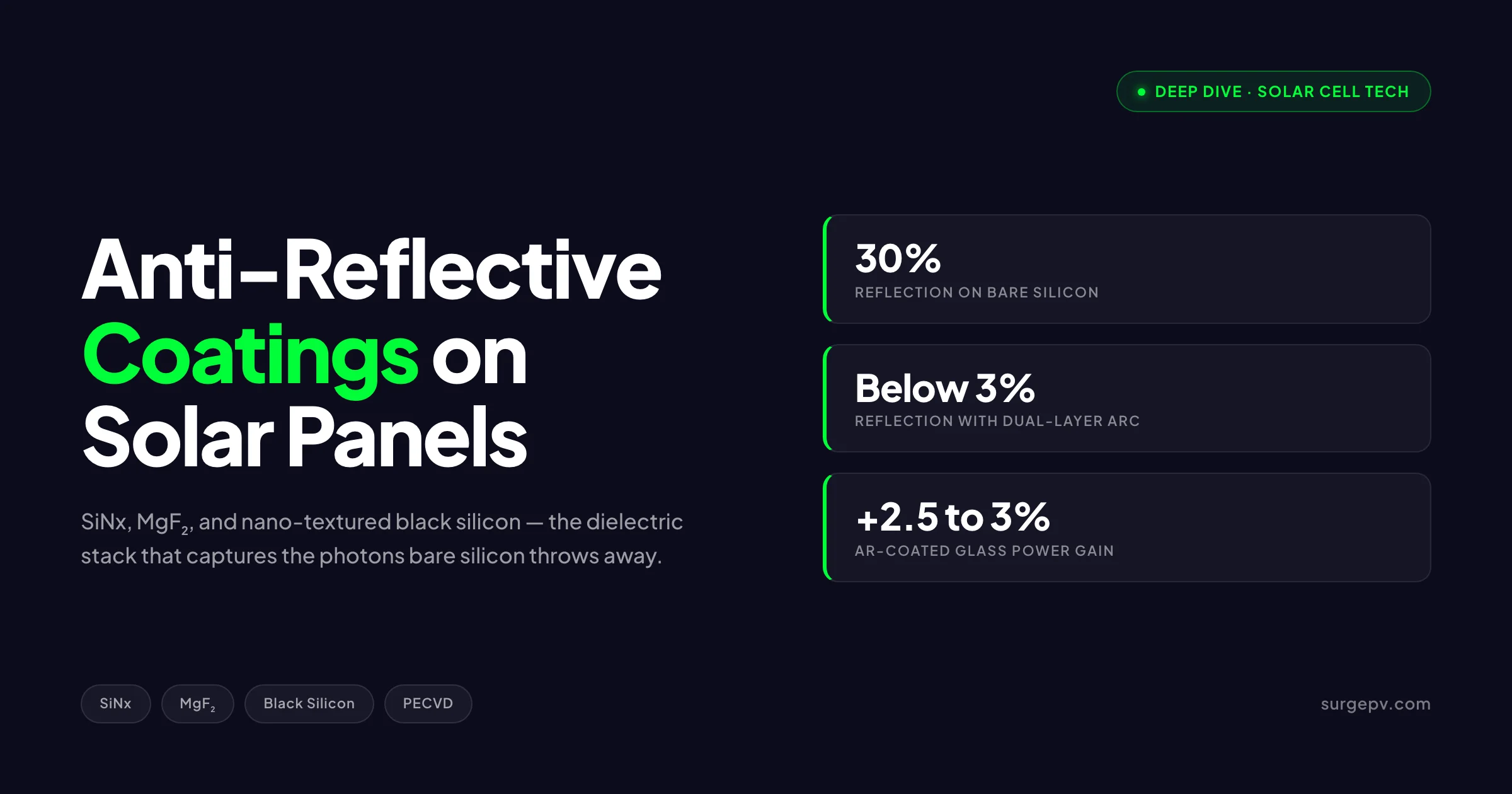
A bare polished silicon wafer reflects 30% of incoming sunlight. Stack a magnesium fluoride film on top and the reflection falls under 3%. The double-layer also showed 95.96% experimental transmittance, a 3.75 eV optical bandgap, and a 729-microsecond carrier lifetime. Dense multilayer SiO2/ZrO2 emerging Glass transmission gain. 3.0-3.5%. 4.5-5.2% Anti-soiling integration.
A bare polished silicon wafer reflects 30% of incoming sunlight. A 75-nanometer silicon nitride layer drops that to 5%. Stack a magnesium fluoride film on top and the reflection falls under 3%. That 27-percentage-point swing in light capture is why every modern crystalline silicon cell shipped in 2026 carries an engineered dielectric coating, and why premium modules add a second anti-reflective layer to the cover glass itself.
A bare polished silicon wafer reflects 30% of incoming sunlight. Stack a magnesium fluoride film on top and the reflection falls under 3%. The double-layer also showed 95.96% experimental transmittance, a 3.75 eV optical bandgap, and a 729-microsecond carrier lifetime.
TL;DR
Anti-reflective coatings (ARCs) on solar cells and module glass cut reflection losses from 30% on bare silicon to under 3% on optimized dual-layer stacks. Silicon nitride dominates at the cell level, applied by PECVD at 75 nm thickness, with the bonus of surface passivation. Glass-side ARCs use porous SiO2 sol-gel or MgF2 multilayers for 3-4% additional yield. Black silicon nano-textures push reflection toward 1%. Together these coatings deliver 3-7% more annual energy from the same silicon, the same area, and the same balance of system.
What you will learn:
- Why an anti-reflective coating works and where in the panel stack it sits
- The five materials that matter: SiNx, SiO2, TiO2, MgF2, and Al2O3
- Refractive index, thickness, and the physics of destructive interference
- Single-layer vs double-layer ARC performance gaps
- Black silicon, pyramidal texturing, and how surface geometry beats coatings alone
- Glass-side anti-reflective coatings and the 3.4-3.7% energy yield gain they deliver
- Anti-soiling coatings, durability under IEC 61215, and field lifetimes
- What this means for module selection, solar design software, and BOM specification
Latest Updates: Anti-Reflective Coating Research in 2026
The research front in 2026 has shifted from “do ARCs work” to “how do we make them last 30 years.” Three threads dominate the literature this year.
n-TOPCon dual-layer SiNx is the new production benchmark. A February 2026 paper in Energy Technology reported optimized graded SiNx coatings on n-TOPCon cells. The double-layer SiNx (DLAR) configuration with a 55 nm top layer at refractive index 1.90 and a 30 nm bottom layer at index 2.10 achieved 24.21% power conversion efficiency in SunSolve simulations, against 23.73% for the best single-layer SiNx. Short-circuit current density rose from 40.51 to 40.88 mA per square centimeter. The double-layer also showed 95.96% experimental transmittance, a 3.75 eV optical bandgap, and a 729-microsecond carrier lifetime. These are production-ready numbers, not lab curiosities.
Glass-side ARCs are growing 5%+. A 2026 study from Spain published in pv magazine reported a porous silica anti-reflective coating that boosts PV glass optical transmission by 5.2%, balancing durability and mechanical stability through optimized sol-gel chemistry with tunable MTES/TEOS ratios and Pluronic P-123 pore-forming agents. Also see: Spain net metering. For the latest details on Spain, see Hotel Solar + EV Charging Case Study.
Anti-soiling coatings are clearing IEC 61215. Commercial products from Opus Materials and others now report water contact angles above 106 degrees after 1,000 hours of UV exposure per IEC 61215-17 MQT13. Damp heat testing remains the principal failure mode, with crater-like defects forming after 500 hours of 85/85 conditions, but new functionalized silica nanoparticle formulations are closing the gap.
| Coating Stage | 2024 Industry Standard | 2026 Industry Standard |
|---|---|---|
| Cell ARC | Single-layer SiNx, 80 nm | Graded dual-layer SiNx, 75+30 nm |
| Cell-level reflection | 6-8% | 3-5% |
| Glass ARC | Single-layer porous SiO2 sol-gel | Dense multilayer SiO2/ZrO2 emerging |
| Glass transmission gain | 3.0-3.5% | 4.5-5.2% |
| Anti-soiling integration | Optional, premium tier | Standard on tier-1 commercial modules |
Why Bare Silicon Reflects So Much Light
Silicon’s refractive index is roughly 3.9 in the visible range. Air’s is 1.0. When light crosses a sharp boundary between two materials with different refractive indices, Fresnel reflection occurs. The reflection coefficient at normal incidence follows the simple formula R = ((n1 - n2) / (n1 + n2))^2. Plug in 1.0 and 3.9 and the math returns 0.349, or 34.9%.
That is a third of the available sunlight, gone before a single electron-hole pair gets generated.
Think of the AR coating on a pair of eyeglasses or a camera lens. Without it, the lens acts like a mirror at certain angles. With a thin dielectric layer engineered to half the wavelength, two reflected wavefronts interfere destructively and cancel. The light has nowhere to go but through the glass. The same physics applies to solar cells, except instead of crystal clear vision you get more electrons.
The trick is matching the refractive index of the coating to the geometric mean of the two materials it sits between. For silicon under air, the ideal coating has n equal to the square root of 3.9, which is 1.97. Silicon nitride sits at n = 2.0 to 2.05. That is not a coincidence. The PV industry standardized on SiNx precisely because its refractive index lands almost exactly where the math wants it.
Why thickness matters as much as material
The ARC layer must be exactly one quarter of the design wavelength inside the coating. For silicon nitride targeting 600 nm light, the layer thickness is 600 / (4 x 2.0) = 75 nm. Off by 10 nm and the destructive interference shifts toward a wavelength where you wanted constructive transmission. This is why PECVD process control matters so much during cell production.
The Five ARC Materials That Matter in 2026
Every commercial ARC stack on the market today uses one or more of five dielectric materials. Each plays a specific role determined by its refractive index and its compatibility with the underlying substrate.
Material Properties Reference Table
| Material | Refractive Index (n) | Typical Thickness | Primary Role | Deposition Method |
|---|---|---|---|---|
| Silicon Nitride (SiNx) | 1.9 – 2.9 (tunable) | 70–80 nm | Cell ARC + passivation | PECVD |
| Silicon Dioxide (SiO2) | 1.46–1.50 | 5–30 nm (or 100 nm porous) | Passivation, glass ARC | Thermal oxide, sol-gel |
| Titanium Dioxide (TiO2) | 2.4–2.6 | 50–60 nm | Legacy cell ARC, photocatalytic | Sputtering, sol-gel |
| Magnesium Fluoride (MgF2) | 1.32–1.38 | 100–110 nm | DLARC top layer | E-beam, sputtering |
| Aluminum Oxide (Al2O3) | 1.6–1.8 | 5–20 nm | Rear/front passivation, PERC | ALD |
Silicon Nitride: The Workhorse
SiNx is the dominant ARC in every cell line shipping today, whether PERC, TOPCon, or HJT architecture. Its refractive index can be tuned between 1.9 and 2.9 by adjusting the silicon-to-nitrogen ratio during PECVD deposition. Increase the silane (SiH4) flow relative to ammonia (NH3) and the film gets more silicon-rich, refractive index climbs, and the optical bandgap narrows. Reverse the ratio and you get a nitrogen-rich, lower-index, more transparent film.
The dual function is what made SiNx unbeatable. It blocks reflection optically while simultaneously passivating the silicon surface. The film contains positive fixed charges that repel electrons from the surface and hydrogen atoms that bond to dangling silicon bonds. Without that surface passivation, even an optically perfect ARC would lose 1-2 percentage points of efficiency to surface recombination.
Silicon Dioxide: The Transition Layer
Thermal SiO2 is grown on the silicon by oxidation at 800-1100 degrees Celsius. It is too transparent to act as a single-layer ARC on silicon (refractive index 1.46 is too low), but it serves as an intermediate buffer between silicon and SiNx in stacked designs, and it shows up as the bulk material in glass-side porous SiO2 coatings.
Titanium Dioxide: The Early ARC
In the 1980s and 1990s, sputtered TiO2 was the standard solar cell ARC. Its refractive index of 2.4 is well-matched to silicon and it can be deposited at low temperatures. TiO2 lost market share to SiNx in the 2000s because it lacks the surface passivation that SiNx delivers, but it remains useful as a high-index bottom layer in some DLAR designs and for photocatalytic self-cleaning glass coatings.
Magnesium Fluoride: The DLARC Cap
MgF2’s refractive index of 1.38 is the lowest of any practical solid dielectric. That low index makes it the preferred top layer in double-layer stacks above either SiNx (on cells) or air (on glass). MgF2 is deposited by electron-beam evaporation, sputtering, or reactive magnetron sputtering using a metallic magnesium target with CF4 reactive gas. Films can reach n = 1.32 after thermal annealing.
Aluminum Oxide: The Passivation Specialist
Al2O3 deposited by atomic layer deposition (ALD) is the passivation layer of choice for PERC and TOPCon rear surfaces. Its negative fixed charge density makes it excellent for passivating p-type silicon. While Al2O3 is not the primary anti-reflective layer in most stacks, it is part of the overall optical management on high-efficiency cells.
Single-Layer vs Double-Layer ARC: The Bandwidth Trade-Off
A single-layer ARC can perfectly cancel reflection at exactly one wavelength. Pick that wavelength to be around 600 nm, near the peak of the solar spectrum, and you get the strongest annual energy boost. But at 400 nm and 1000 nm, reflection climbs back toward 10-15% because the quarter-wave condition no longer holds.
A double-layer ARC stacks two coatings with different refractive indices and thicknesses. The top layer (low n, like MgF2 at 1.38) and bottom layer (high n, like SiNx at 2.0 or CeO2 at 2.46) together produce two reflection minima separated in wavelength. The result is broadband suppression across the full solar spectrum.
Performance Comparison
| Configuration | Mean Reflection (400-1100 nm) | Best Reported Cell Efficiency | Cost Premium |
|---|---|---|---|
| Polished bare silicon | ~34% | n/a (reference) | 0 |
| Alkaline-textured silicon | ~11% | n/a (reference) | Baseline |
| Pyramidal texture + SiNx SLAR | ~6-7% | 23.73% (n-TOPCon, 2026) | Baseline |
| Pyramidal texture + SiNx DLAR | ~3-4% | 24.21% (n-TOPCon, 2026) | +$0.005-0.01/W |
| Pyramidal + MgF2/SiNx DLAR | ~2-3% | 22.71% (HBT) | +$0.02-0.03/W |
| Pyramidal + MgF2/CeO2 DLAR | ~1.87% | 19.9% (BCSC) | Research-only |
| Black silicon (RIE, no ARC) | ~1-3% | 22.1% (Aalto/UPC, ALD) | +$0.04-0.06/W |
The data point worth noting: black silicon with atomic layer deposition passivation has hit 22.1% efficiency, and texture-on-texture nano-micron composite structures have pushed bifacial TOPCon cells above 23% on industry-sized 158.75 x 158.75 mm wafers in 2024-2025 research. The roadmap is clear, even if cost has kept these off mass production lines so far. See Bifacial Solar Panel Design Guide for detailed guidance.
Contrarian view: most installers shouldn’t care which ARC is on their module
Cell-level ARC is a manufacturer decision. By the time a module reaches an EPC, the SiNx is locked under glass and EVA, the warranty is written, and the spec sheet quotes the bottom-line efficiency that already includes the coating. What you can specify is glass-side ARC. That is the one that affects your bid price, your maintenance schedule, and your year-one production curve. If you are negotiating with two suppliers and one offers AR-coated tempered glass and the other does not, the 3-4% energy yield difference is real and worth pricing into the deal. Do not get distracted by SiNx DLAR claims that you cannot verify and cannot influence.
Surface Texturing: When Geometry Beats Chemistry
Coatings work by tuning the refractive index step. Texturing works by removing the step entirely. A pyramidally textured silicon surface creates a graded-index medium where light entering at an oblique angle reflects sideways into other pyramids rather than bouncing back out.
Pyramidal Texturing on Monocrystalline Silicon
Standard alkaline etching with KOH or NaOH on (100)-oriented monocrystalline wafers preferentially exposes (111) crystal planes. The result is a forest of 3-10 micrometer pyramids covering the entire wafer surface. Reflection drops from 34% on a polished wafer to about 11% on the textured surface alone. Add a 75 nm SiNx ARC over the pyramids and reflection falls below 6%. See our guide on Commercial Rooftop Solar Case Study Italy for more. For Italy-specific information, see Italy Solar Feed-in Tariffs.
Pyramidal texturing is now table-stakes for monocrystalline silicon cells. Every PERC, TOPCon, and HJT cell ships with textured front surfaces. The exception is multicrystalline silicon, where random crystal orientation prevents anisotropic etching from producing clean pyramids.
Acidic Etching on Multicrystalline Silicon
Multi-Si wafers use isotropic acidic etching (HF/HNO3/CH3COOH) to produce a more uniform but less effective rounded-pit texture. Surface reflection on textured multi-Si sits around 25-30%, which is why multi-Si cells historically lagged mono-Si by 1-2 efficiency points. With the multi-Si market collapsing under mono-Si and TOPCon competition, this gap matters less every year.
Black Silicon: Nano-Texturing for Sub-1% Reflection
Black silicon is the most aggressive surface treatment available. Two production routes dominate:
Reactive ion etching (RIE). SF6 and O2 gases in a plasma chamber etch silicon while simultaneously depositing SiOxFy passivation that acts as a self-mask. The result is a needle-like nanostructure with feature sizes of 50-70 nm and depths of 1-10 micrometers. Cryogenic RIE produces total reflectance of 1% plus or minus 0.5% across 450-1000 nm on full 100 mm wafers.
Metal-assisted chemical etching (MACE). Silver or gold nanoparticles catalyze localized HF/H2O2 etching that produces vertical nanopores. NREL achieved 18.2% efficient black silicon cells with this method. The newer NPP (nano-pore on pyramid) approach combines alkaline pyramidal texturing with RIE nano-texturing on top, delivering >23% efficient bifacial TOPCon cells on full-size 158.75 mm wafers.
The Recombination Trade-Off
Black silicon’s enormous surface area cuts both ways. More surface means more potential recombination sites. Early black silicon cells suffered from elevated emitter recombination current density that cancelled the photocurrent gain. The breakthrough came when Aalto University in 2015 reported 22.1% efficiency by adding atomic layer deposition (ALD) Al2O3 passivation and moving all metal contacts to the rear (an IBC architecture, see IBC solar cells explained for more detail).
Black silicon will likely show up in mainstream production in the late 2020s, paired with TOPCon or HJT architectures that minimize surface recombination through ultra-thin passivation films.
Glass-Side Anti-Reflective Coatings: The Underrated Gain
While cell-level ARC is sealed inside the laminate, the cover glass interface is the first light hits when entering the module. That glass-air boundary alone causes another 4% reflection loss on plain tempered glass.
The Ballif 2004 Study
The reference work on glass-side ARC is Ballif et al. 2004, a joint project between Flabeg, Merck KGaA, and the Fraunhofer Institutes ISC and ISE. They scaled porous SiO2 sol-gel coating to industrial 1.5 x 2.5 m glass panels using dip-coating and a 630-degree-Celsius thermal cure that runs simultaneously with glass toughening.
Headline numbers:
- Current gain at STC: 2.65%
- Modeled annual energy yield gain: 3.4-3.7%
- Process cost premium: negligible (cure step folds into tempering)
- Coating coverage of commercial modules in 2026: over 90%
The annual gain (3.4-3.7%) exceeds the STC current gain (2.65%) because oblique-incidence light, more common in morning and afternoon hours, benefits more from the AR coating than direct overhead light does. The coating effectively flattens the daily generation curve by capturing more low-angle photons.
How Porous SiO2 Achieves a 1.22 Refractive Index
The ideal refractive index for a single-layer ARC between air (n = 1.0) and glass (n = 1.5) is 1.22, the geometric mean. No solid material has a refractive index that low. MgF2 at 1.32 is the closest, but it is expensive and hard to bond to glass.
Porous silica solves the problem by mixing solid SiO2 (n = 1.47) with engineered air voids (n = 1.0). The effective medium refractive index becomes a weighted average of the two. With 50% porosity, the bulk index drops to roughly 1.23, hitting the ideal almost exactly. Sol-gel chemistry with surfactant pore-forming agents allows continuous tuning of porosity from 0 to 60%.
The 2026 Spanish study from pv magazine reported 5.2% optical transmission gain on porous silica coatings made with optimized MTES/TEOS ratios and Pluronic P-123 templates, the highest commercially viable figure published to date.
Specify AR-coated glass in your module BOM
SurgePV’s module library tracks glass treatment per SKU so you can model the energy yield difference at design time. See how solar design software makes ARC selection a measurable decision.
Book a DemoNo commitment required · 20 minutes · Live project walkthrough
For a direct comparison, see Arka 360 vs SurgePV.
Manufacturing Processes: How ARC Films Are Made
The cost and quality of an ARC depends as much on the deposition process as on the material chemistry. Three dominant processes cover 95%+ of commercial production.
PECVD for Cell-Level SiNx
Plasma-enhanced chemical vapor deposition is the workhorse for silicon nitride. Cells pass through a vacuum chamber where silane (SiH4) and ammonia (NH3) gases dissociate in an RF plasma and deposit a silicon nitride film at 350-450 degrees Celsius. The plasma temperature allows deposition without overheating the silicon junction.
PECVD production rates run 2,000-3,000 wafers per hour per chamber on modern lines. The process is mature, well-understood, and cheap enough that even budget Tier 2 cell manufacturers use it. Process variation between manufacturers shows up in refractive index tuning, hydrogen content, and uniformity across the wafer.
Sol-Gel Dip Coating for Glass-Side ARC
Sol-gel processes prepare a silica precursor solution (typically TEOS, ethanol, water, and an acid catalyst) and dip the cover glass into the solution at controlled withdrawal rates. The deposited film cures during glass tempering at 600-700 degrees Celsius, where the organic components burn off and leave behind a porous silica network.
This process scales naturally to industrial glass sizes (now up to 2.4 x 1.3 m for bifacial modules). It is cheap, requires no vacuum equipment, and the only added energy cost is the thermal cure that the glass already needs for tempering.
E-Beam Evaporation and Sputtering for MgF2
MgF2 layers are deposited by electron-beam evaporation or reactive magnetron sputtering. The substrate temperature ranges from 50 to 240 degrees Celsius, and rapid thermal annealing afterward can further reduce the refractive index toward 1.32. These vacuum processes are slower and more expensive than PECVD or sol-gel, which is why MgF2 is reserved for premium modules and specialty applications like space-grade cells.
ALD for Al2O3 Passivation
Atomic layer deposition produces ultra-thin (5-20 nm), conformal Al2O3 films using sequential trimethylaluminum (TMA) and water vapor pulses. Each pulse deposits a monolayer. ALD is slow but produces films of unmatched uniformity, which is essential for thin passivation layers on textured surfaces.
Durability: What IEC 61215 Reveals About ARC Lifetime
The longstanding tension in glass-side ARC research is the trade-off between optical performance (which favors high porosity, low density, and lots of light-trapping features) and durability (which favors dense, hard, smooth surfaces).
IEC 61215 Test Suite for ARCs
| Test | Conditions | What It Simulates |
|---|---|---|
| Damp Heat (DH) | 85°C / 85% RH, 1,000 hours | Tropical climate exposure |
| UV Exposure | 60 kWh/m2 UV, 1,000 hours | High-altitude/desert UV stress |
| Thermal Cycling | -40°C to +85°C, 200 cycles | Daily temperature swings |
| Sand Erosion | Custom standards | Desert dust abrasion |
| Adhesion | Tape pull, scribe test | Coating-substrate bonding |
| Abrasion (wet slurry) | Custom standards | Cleaning brush wear |
Field Lifetime Reality
Porous SiO2 AR coatings, the dominant glass-side technology, are vulnerable to damp heat. After 1,000 hours of 85/85 testing, weighted average reflectance increases by about 1% absolute, and maximum transmittance can drop 4% after 14 days of harsh humid exposure. Real-world useful lifetimes in coastal and tropical climates land around 8 years, well below the 25-30 year module warranty.
The 2025 Progress in Photovoltaics paper from Zeng et al. proposed a dense five-layer SiO2/ZrO2 design that survives wet-slurry abrasion testing and maintains optical performance through accelerated DH cycles. This is the path forward for ARCs that match the module warranty period.
Anti-Soiling Combined ARCs
The newest commercial coatings combine anti-reflective and anti-soiling functions in a single layer. Functionalized silica nanoparticles provide both surface roughness for light trapping and low surface energy for water repellency. The water contact angle is the key metric. Above 90 degrees, the coating is hydrophobic. Above 120 degrees, it is superhydrophobic and provides strong self-cleaning under rainfall.
Commercial products like Solar Sharc (Opus Materials) maintain contact angles around 106 degrees after 1,000 hours of IEC 61215-17 MQT13 UV exposure. The remaining weakness is damp heat, where moisture entrapment forms 10-12 micrometer crater-like defects on the surface after 500 hours. This is fine for arid climates and a real concern for tropical installations.
For more detail on soiling losses and how to design around them, see our guides on soiling losses and the solar panel cleaning guide.
ARC Decision Matrix: What to Specify and When
Most installers and EPC engineers do not pick the cell-level ARC. That is locked when you choose a module SKU. What you can influence is the glass treatment, the anti-soiling tier, and your maintenance schedule. Here is how to make those calls.
| Scenario | Cell ARC | Glass ARC | Anti-Soiling | Estimated Annual Gain |
|---|---|---|---|---|
| Residential rooftop, temperate climate | SiNx SLAR (standard) | Optional | Optional | Baseline |
| Commercial rooftop, mid-latitude | SiNx SLAR | AR-coated tempered glass | Optional | +3.0-3.5% |
| Utility ground-mount, dry climate | SiNx SLAR or DLAR | AR-coated | Hydrophobic ASC | +4.5-5.5% |
| Utility ground-mount, desert | SiNx DLAR (premium) | AR + ASC integrated | Required | +5.5-7.0% |
| Floating PV, coastal | SiNx SLAR | Dense multilayer ARC | Hydrophobic ASC | +3.5-4.5% |
| Snow climate, steep-tilt rooftop | SiNx SLAR | AR-coated | Hydrophilic anti-icing | +3.0-4.0% |
| Carport / agrivoltaic, high-soiling | SiNx SLAR | AR + ASC integrated | Required | +4.5-6.0% |
The decision framework boils down to three questions:
- What is the soiling rate at this site? PM10 levels, rainfall frequency, and dust deposition determine whether anti-soiling justifies its 2-4% module price premium.
- What is the project’s IRR sensitivity to year-one production? If you are within 50 basis points of the financing threshold, glass ARC may swing the deal.
- What is the cleaning cost over 25 years? Anti-soiling pays back through reduced O&M labor, not just higher production. In some desert utility projects, ASC saves 30-50% of cleaning budget.
For full system economics, run the numbers in your generation and financial tool before committing to a glass treatment tier.
ROI Examples: Modeling the Glass ARC Premium
Two real-world numbers help calibrate the decision.
Example 1: 100 kW Commercial Rooftop, Spain
- System size: 100 kWdc
- Baseline annual yield: 1,550 kWh/kWp = 155,000 kWh/year
- ARC-coated glass premium: $0.015/W = $1,500 capex
- Annual yield gain with glass ARC (3.5%): 5,425 kWh
- PPA price: $0.085/kWh
- Annual revenue gain: $461
- Simple payback: 3.25 years
- 25-year NPV at 7% discount: $4,879
The glass ARC premium pays back in about three years and contributes nearly $5,000 in net present value over the project life. For commercial rooftops at this scale, AR-coated glass is almost always the right call.
Example 2: 5 MW Utility Ground-Mount, Rajasthan
- System size: 5 MWdc
- Baseline annual yield: 1,750 kWh/kWp = 8,750,000 kWh/year
- AR + ASC premium: $0.025/W = $125,000 capex
- Annual yield gain (5.5%): 481,250 kWh
- Soiling cleaning savings: $15,000/year reduced labor
- PPA price: $0.045/kWh
- Annual revenue gain: $21,656 + $15,000 = $36,656
- Simple payback: 3.4 years
- 25-year NPV at 8% discount: $268,000
In a high-soiling utility application, the combined AR plus anti-soiling treatment pays back through both higher production and reduced O&M.
These numbers are realistic for 2026 market pricing. They will improve as ARC durability extends through the new dense multilayer designs entering production.
Future Directions: Photonic Crystals, Plasmonic ARC, and Perovskite-Compatible Stacks
The next decade of ARC research is moving in three directions worth watching.
Photonic crystal ARCs. Periodic dielectric structures with subwavelength features can produce reflection minima across a much broader band than thin-film stacks. Lab prototypes have demonstrated near-zero reflection from 350 to 1,100 nm. Manufacturing these at commercial scale on textured silicon is the open challenge.
Plasmonic light-trapping coatings. Metal nanoparticles (silver, gold, aluminum) embedded in dielectric coatings can scatter light into the silicon at high angles, effectively extending the optical path length. This is particularly interesting for thin-film silicon and tandem cells where bulk absorption is weak.
Perovskite-compatible ARC. Perovskite-on-silicon tandem cells (see perovskite-silicon tandems) need ARC stacks that work across a broader spectrum than silicon-only cells. The wide bandgap perovskite top cell absorbs strongly in the 400-600 nm range, while the silicon bottom cell absorbs at 600-1,100 nm. Conventional SiNx ARC, optimized for silicon, leaves 5-7% reflection in the perovskite absorption band. New tandem-optimized stacks using SiO2/SiNx/MgF2 triple layers are emerging from research groups at NREL, KAUST, and Fraunhofer ISE.
For more on next-generation cell architectures and how their light-management requirements differ from incumbents, see our deep dive on solar cell efficiency records.
How Anti-Reflective Coatings Interact With Solar Design Software
For installers and project developers, the practical question is not “what is the refractive index of SiNx” but “how does ARC selection show up in the energy model and the BOM.”
Modern solar design software treats glass-side ARC as a per-module property that flows into the yield calculation. SurgePV’s module library tags AR-coated glass with a transmission gain factor that adjusts the spectral response at oblique incidence, the regime where ARC matters most.
When you select a module SKU with AR-coated glass, the software:
- Adjusts the angular incidence loss model (Sandia or De Soto) to reflect the lower reflection at oblique angles
- Updates the spectral mismatch factor to account for the broader spectral transmission
- Recalculates the annual yield in the system loss diagram
- Flags the AR-coating premium in the BOM cost rollup
This matters because the difference between “specify any module” and “specify AR-coated module” is roughly 3-5% of annual energy yield. On a 100 kW system at $0.10/kWh, that is $1,400-$2,400 of recurring annual revenue. Sophisticated buyers will and should ask for it.
The same logic applies to shadow analysis. A site with morning shading from trees, where the unshaded hours are heavy on oblique-incidence light, benefits disproportionately from glass-side ARC. The modeling tool needs to capture this interaction or you will under-predict the value of the coating. See Solar Shading Analysis Guide for detailed guidance.
Conclusion: Three Decisions for 2026 Projects
Anti-reflective coatings are no longer an exotic premium upgrade. They are a default specification for any commercial or utility-scale solar project. The question is not whether to use them but which tier to specify.
Here are the three decisions that matter:
-
Always specify AR-coated tempered glass on commercial and utility projects. The 3-4% annual yield gain pays back in 3-5 years and adds 3-5% to project NPV. The cost premium of $0.010-$0.015/W is rarely material in modern BOMs.
-
Specify anti-soiling integrated ARC in dust-heavy climates. PM10 above 50 ug/m3, infrequent rainfall, or PV plants on agricultural land all favor the hydrophobic ASC tier. The annual cleaning labor savings often exceed the optical gain.
-
Track ARC degradation in O&M monitoring. Year-one yield numbers will be optimistic. Build a 0.5% per year ARC degradation factor into your IRR model for the first decade and verify against IV-curve measurements at year 5 and year 10. The new dense multilayer ARCs may outperform this assumption, in which case you will have upside.
For the engineering teams designing modules, the roadmap is clear. Dual-layer SiNx is moving from research to production lines in 2026. Black silicon nano-textures are 2-3 years from mass-market viability. Glass-side ARCs are evolving from single-layer porous SiO2 toward dense multilayer stacks that survive the full module warranty period.
What stays constant is the basic physics. Light wants to reflect. Coatings convince it not to. Every 1% of reflection eliminated translates roughly 1:1 into annual energy yield. That is the most leveraged engineering decision in the entire module stack.
Frequently Asked Questions
What is an anti-reflective coating on a solar panel?
An anti-reflective coating (ARC) is a thin dielectric layer applied to a solar cell or its cover glass to reduce light reflection. Bare silicon reflects about 30% of incident light. A single SiNx layer at 75 nm cuts that to roughly 5%. A dual MgF2/SiNx stack drops it under 3%. The result is more photons reaching the absorber and 3-7% higher annual energy yield.
What material is most commonly used for solar cell ARC?
Silicon nitride (SiNx) is the dominant cell-level anti-reflective coating in 2026. It is applied by plasma-enhanced chemical vapor deposition (PECVD) at about 75 nm thickness with a refractive index near 2.05. SiNx does double duty as both an optical anti-reflective layer and a surface passivation layer that suppresses charge carrier recombination.
Why is MgF2 used in double-layer ARC?
Magnesium fluoride has a refractive index of 1.38, very close to the theoretical ideal of 1.22 for the top layer above glass or a higher-index dielectric. It sits above a SiNx or CeO2 layer and produces destructive interference across a wider wavelength band than a single layer can manage. MgF2 stacks push reflection below 2% from 400 to 1100 nm.
What is black silicon and how does it reduce reflection?
Black silicon is a nano-textured silicon surface produced by reactive ion etching (RIE) or metal-assisted etching. The needle-shaped features are smaller than the wavelength of visible light, so the surface behaves as a graded-index medium rather than a sharp boundary. Reflection falls from roughly 30% on a polished wafer to 1-3% across the 300-1000 nm range with no additional ARC needed.
Does anti-reflective coating on solar glass really increase energy yield?
Yes. The landmark Ballif et al. study with Flabeg and Fraunhofer ISE measured a 2.65% current gain at standard test conditions and modeled a 3.4-3.7% annual energy yield gain from porous SiO2 sol-gel coating on tempered solar glass. The gain is higher at oblique incidence, which is why morning and afternoon energy capture improves more than midday output.
How long does anti-reflective coating last on a solar panel?
Cell-level SiNx is sealed inside the laminate, protected by glass and EVA, and lasts the full 25-30 year panel life with no measurable degradation. Glass-side porous SiO2 ARC is more vulnerable. Field studies show useful lifetimes around 8 years in harsh climates due to abrasion, damp heat, and soiling. New dense multilayer ARCs are emerging to extend that toward the full warranty period.
Do solar panels still need cleaning if they have an anti-soiling coating?
Yes, but less often. Hydrophobic anti-soiling coatings reduce dust adhesion and improve rain self-cleaning, but they do not eliminate soiling losses entirely. In desert climates with PM10 above 100 ug/m3, even coated modules need cleaning every 4-8 weeks. The coatings shift the economics of cleaning frequency rather than removing the need.
Can I add anti-reflective coating to existing solar panels?
Aftermarket spray-on or wipe-on hydrophobic and anti-reflective products exist, but they do not match factory-applied coatings in optical performance or durability. Most provide modest soiling reduction rather than measurable light transmission gain. For new installations, the better path is to specify modules from manufacturers using AR-coated glass at the factory.
Further Reading and Sources
- Alamgeer et al. 2026, “Silicon Nitride (SiNx) Single and Double-Layer Coatings for n-TOPCon Solar Cells,” Energy Technology
- Ballif et al. 2004, “Solar glass with industrial porous SiO2 antireflection coating,” Solar Energy Materials and Solar Cells
- PVEducation: Double Layer Anti-Reflection Coatings
- PV Magazine, April 2026: Porous silica AR coating increases PV glass transmission by 5.2%
- The performance and durability of Anti-reflection coatings for solar module cover glass, Solar Energy
- Zeng et al. 2025, “Revisiting Photovoltaic Module Antireflection Coatings: A Novel, Dense Sol-Gel Design,” Progress in Photovoltaics
- Black silicon (Wikipedia overview)
- Recent Applications of Antireflection Coatings in Solar Cells, Photonics
Related SurgePV reading: