Quick Answer
A 50 MW solar farm in southern Spain looked routine at commissioning. By month 18 the asset manager could not ignore the production curve: yield had dropped 8% against the P50 model, well outside expected first-year degradation. Less than 3% loss at 1500V, but production volumes declining Typical n-type TOPCon PID test result.
A 50 MW solar farm in southern Spain looked routine at commissioning. By month 18 the asset manager could not ignore the production curve: yield had dropped 8% against the P50 model, well outside expected first-year degradation. An aerial thermography sweep found the pattern most field engineers dread: thermal hotspots clustered near the corners of modules at the negative end of every string. Electroluminescence imaging confirmed it. The plant had a textbook case of potential induced degradation, and the EPC was looking at a multi-million-euro warranty claim. None of this should be a surprise in 2026, yet PID-related yield losses still appear in field reports every quarter. The mechanism is well understood, the test standards are mature, and the prevention recipe is documented. What is missing is consistent execution from specification through commissioning. This guide walks through the physics of PID, the difference between shunting and polarisation types, the IEC 62804 test family, and the practical prevention measures that should appear in every modern bill of materials. Also see: Spain net metering.
A 50 MW solar farm in southern Spain looked routine at commissioning. By month 18 the asset manager could not ignore the production curve: yield had dropped 8% against the P50 model, well outside expected first-year degradation. Less than 3% loss at 1500V, but production volumes declining Typical n-type TOPCon PID test result. See our guide on Hotel Solar + EV Charging Case Study for more. For the latest details on Spain, see Solar Panels Spain.
TL;DR — PID in 2026
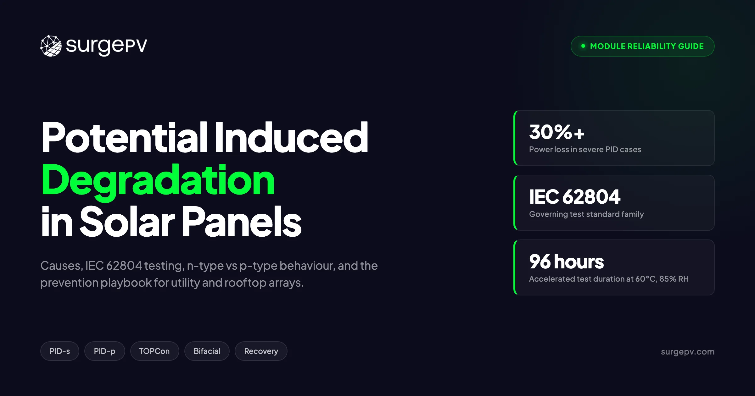
Potential induced degradation is a yield-killing failure mode caused by high system voltage driving ions or charge across a module’s encapsulant and passivation stack. The two dominant types are PID-s (shunting, classic in p-type PERC) and PID-p (polarisation, the one to watch on n-type TOPCon and HJT). IEC TS 62804-1 defines the accelerated test: 96 hours at 60°C and 85% RH with rated system voltage, pass criterion under 5% power loss. Prevention is a stack of choices: PID-resistant cells, POE encapsulant, tight glass and ARC specs, functional negative grounding, and a PID recovery box for transformerless topologies. Modules that pass IEC 62804 at 1500V are now the bankability baseline for utility-scale projects.
What this guide covers:
- The physics of PID, broken into its two mechanisms and why they behave differently
- Why p-type PERC suffered most historically and why n-type TOPCon is not automatically immune
- A full breakdown of IEC 62804-1, IEC 62804-2, the 2025 revision, and TÜV’s QM-PID protocol
- A diagnostic table linking root causes to module, system, and environmental factors
- Module-level prevention (encapsulants, glass, ARCs) and system-level prevention (grounding, PID boxes)
- A field-tested step-by-step procedure for detecting PID in deployed arrays
- The bankability and warranty implications of PID failures
- Recent 2025-2026 research on PID-p in TOPCon and what it means for procurement
Latest Updates: PID Standards and Module Specs in 2026
The PID landscape has shifted measurably in the last 18 months. The table below summarises the state of the test standards, dominant cell technologies, and the typical PID specs you should expect on tier-1 datasheets in 2026.
| Topic | 2026 Status |
|---|---|
| IEC TS 62804-1 (PID-s test) | Mature, with 2025 revision adding light-plus-voltage method for PID-p |
| IEC TS 62804-2 (outdoor extended) | In active use for premium project qualification |
| TÜV QM-PID protocol | Doubled stress duration (192h) for high-humidity climates |
| Typical p-type PERC PID test result | Less than 3% loss at 1500V, but production volumes declining |
| Typical n-type TOPCon PID test result | Less than 2% loss at 1500V; new PID-p concerns under negative bias with humidity |
| HJT module PID resistance | Generally excellent due to TCO-based cell architecture |
| Bifacial PID test requirements | Sequential front and rear stress now standard for utility procurement |
| Industry “PID-free” claim threshold | Power loss less than 5% per IEC 62804-1 |
Key Takeaway — PID Is Not Solved, Just Better Managed
”PID-free” labels on a datasheet mean a module passed a 96-hour accelerated test, not that it will never experience PID over 25 years in the field. Specify projects to require both IEC 62804 certification and the actual test report, then verify the test voltage matches your project’s system voltage. A module tested at 1000V is not automatically safe for a 1500V plant.
What Is Potential Induced Degradation?
Potential induced degradation is the irreversible or partially reversible loss of solar module power output caused by a sustained voltage difference between the solar cells and the module frame or other grounded surfaces. The mechanism is electrochemical and it gets worse with heat, humidity, time, and applied voltage.
Think of a solar string in a large array. The system voltage might be 1500V DC end to end. The frames of every module in the string sit at ground potential. The cells at the negative end of the string therefore see nearly the full system voltage between cell and frame. That field, combined with temperature and humidity, drives one of two damage mechanisms inside the module laminate.
A Simple Analogy
Imagine pressing a magnet against the back of a glass jar full of iron filings. The filings drift through the glass over time, accumulate on the inner surface, and short out a circuit drawn on the inside wall. That is roughly what happens to sodium ions in soda-lime glass when a module sits under negative bias for years: they drift through the encapsulant, lodge in cell defects, and degrade the p-n junction. The voltage is the magnet. The encapsulant is the soft barrier between glass and cell. The cell is the circuit you do not want shorted.
Pro Tip
When sizing a long string with solar design software, check both the maximum cell-to-ground voltage at the negative end of the string and the module’s tested PID voltage. If the project bus is 1500V and the module is only IEC 62804 qualified to 1000V, the PID risk is being underwritten by the EPC, not the manufacturer.
The Two Types of PID: Shunting and Polarisation
PID is not one mechanism. The two clinically distinct types are PID-s (shunting type) and PID-p (polarisation type). They affect different cell technologies, leave different I-V curve signatures, and respond to different recovery strategies. A third category, PID-c (corrosion type), describes irreversible electrochemical attack on contacts and is rare in modern modules.
PID-s: The Sodium Ion Shunt
PID-s is the historical PID. It is the failure mode that hit p-type PERC and pre-PERC modules in the 2010s and made “PID-free” a marketing term.
The mechanism is well documented. Sodium ions (Na+) are present in the soda-lime glass used for module front cover. Under a negative cell-to-frame potential, those ions migrate out of the glass, drift through the EVA encapsulant, cross the silicon nitride anti-reflective coating, and decorate stacking faults inside the silicon cell. The accumulated Na+ at the stacking faults creates conductive shunt paths across the p-n junction. The shunt resistance Rsh of the cell collapses, fill factor crashes, and module output drops.
The classic I-V signature is a fill factor reduction with relatively preserved short-circuit current. Modules in the most-negative position of a long string degrade first and worst. In severe cases, individual cells turn dark under electroluminescence imaging.
PID-p: The Polarisation Charge Effect
PID-p is the newer concern. It dominates in n-type cells (TOPCon, HJT, IBC) where the front-side passivation stack acts as a capacitor under bias. For more on this topic, see TOPCon vs HJT vs Perovskite Solar Panels.
In an n-type front-emitter cell, the front anti-reflective and passivation layers (SiNx, SiNx/SiO2, AlOx stacks) accumulate fixed and mobile charges under a sustained electric field. That charge sheet inverts or depletes the cell surface, dramatically increasing surface recombination of minority carriers. The cell does not develop a hard shunt. It loses open-circuit voltage, fill factor, and short-circuit current in roughly equal proportion because the entire front surface becomes a recombination sink.
The good news: PID-p is almost fully reversible. Apply a positive bias to the array overnight and the polarising charge dissipates, restoring most of the lost performance within days to weeks.
Side-by-Side Comparison
| Attribute | PID-s (Shunting) | PID-p (Polarisation) |
|---|---|---|
| Dominant in | p-type PERC, older p-type cells | n-type TOPCon, HJT, IBC |
| Root mechanism | Na+ ion migration into Si stacking faults | Charge accumulation in front dielectric stack |
| I-V signature | Fill factor crash, Rsh drop | Voc, FF, and Jsc all drop modestly |
| Reversibility | Partial, often permanent below cell level | Almost fully reversible with reverse bias |
| Polarity that causes damage | Negative cell-to-frame | Negative bias with light or humidity on front |
| Module test method | IEC 62804-1 foil test, 96h, 60°C, 85% RH | IEC 62804-1 (2025) combined light + voltage |
| Primary mitigation | PID-resistant cells, POE encapsulant, aluminosilicate glass | Conductive passivation stack tuning, UV light |
Pro Tip
When you see a tier-1 datasheet that lists only “IEC 62804” with a tick box, ask which sub-method and which polarity. A TOPCon module that passes PID-s at –1500V can still degrade by PID-p under the same field if it has not been qualified to the 2025 light-and-voltage method.
Why P-Type Modules Suffered Most Historically
Up to roughly 2018, almost every large-scale PID incident in the field involved p-type cells. There are three structural reasons.
First, the negative grounding behaviour. In a p-type cell with a positive front emitter and negative back, the negative end of the string sits at a high negative potential relative to the frame. That is exactly the polarity that drives Na+ ions out of soda-lime glass into the cell. Reverse the polarity (positive ground) and PID-s essentially disappears in p-type, which is why early SunPower IBC plants in the US never showed PID even at long string lengths.
Second, the standard module bill of materials. P-type PERC modules dominated the 2010-2020 era used soda-lime glass, EVA encapsulant, and SiNx anti-reflective coatings. Soda-lime glass is sodium-rich. EVA has relatively high ion permeability, especially when warm and humid. SiNx is not a strong barrier to Na+. The whole stack was a sodium delivery system to the cell once the field was applied.
Third, the cell defect density. Standard mc-Si and Cz-Si p-type wafers from the 2010s contained higher densities of stacking faults than today’s Czochralski n-type wafers. More stacking faults means more decoration sites for Na+, and a faster shunt path to form.
Compare this to a modern n-type wafer from a tier-1 supplier in 2025-2026. Stacking fault density is roughly an order of magnitude lower. Ion-blocking encapsulants like polyolefin elastomer (POE) are widely deployed. Glass formulations are tighter. The combination drops PID-s rates to negligible levels in n-type production.
But this is exactly where the story gets more interesting, because n-type modules are not actually immune to PID.
Why Some N-Type Modules Have a Bigger PID Problem Than P-Type Ever Did
The conventional wisdom in 2022 was simple: n-type wins, PID is solved. The conventional wisdom in 2026 is more nuanced, and it deserves a hard look before you sign off on a 1500V TOPCon project.
Recent NREL research on TOPCon modules under field-representative stress, combined with IEC’s 2025 revision of 62804-1 to explicitly include PID-p test protocols, points to a real concern: TOPCon and HJT modules can degrade by PID-p under conditions that are not exotic. Specifically, when the front surface is wet (rain, dew) under low irradiance and the cells sit at high negative cell-to-frame potential, charge accumulates in the front passivation stack and surface recombination spikes.
A study published in 2024-2025 found that under –1000V bias, 50°C, 30% relative humidity over 168 hours, TOPCon glass-glass modules showed measurable PID-p on the front side. With the polarity reversed to +1000V, no impact was reported. Crucially, separate work showed that AM1.5 illumination during the test reduced the degradation to under 3%, while no UV illumination during the same stress produced 28% degradation. The implication is that PID-p in TOPCon is partly a “low-light at high-bias” failure mode, and that field conditions like cloudy mornings with dew can trigger it.
This is not the same conversation as PID-s in p-type. It is also not a reason to avoid n-type. It is a reason to:
- Demand IEC 62804-1 (2025) test reports that include the combined light and voltage method, not just the older 96-hour dark test.
- Verify the actual test voltage matches the project’s system voltage at the negative end of the string.
- Require POE or ionomer encapsulants for utility projects in high-humidity climates.
- Specify front-side passivation stacks that the manufacturer has explicitly tested for PID-p resilience.
Counter-Intuitive Finding
A glass-glass bifacial TOPCon module can be more PID-vulnerable than an older glass-backsheet p-PERC module if the n-type product was qualified only against PID-s and the project sits in a humid, partly cloudy climate. The total PID risk depends on the test method matching the actual stress, not the cell type alone. Treat “n-type so PID is solved” as marketing, not engineering.
For more on this topic, see Bifacial Solar Panel Design Guide.
Root Causes: A Diagnostic Table
PID does not have one cause. It is a stack of contributing factors, any of which can be tuned to prevent the failure. The table below summarises the dominant factors and the lever you have for each.
| Factor | Why It Drives PID | Design Lever |
|---|---|---|
| System voltage (cell to ground) | Higher voltage = stronger electric field = faster ion drift | Limit string length, use functional grounding, install PID box |
| Operating temperature | Higher T accelerates ion mobility exponentially | Roof ventilation, racking standoff, cooler climate site selection |
| Relative humidity inside the laminate | Water enables ion mobility through encapsulant | Edge sealants, low-MVTR backsheets, glass-glass with edge seal |
| Glass sodium content | Soda-lime glass is the Na+ reservoir | Aluminosilicate or chemically-tempered low-Na glass |
| Encapsulant resistivity and ion permeability | Lower resistivity EVA passes ions easily | POE or ionomer encapsulant |
| Anti-reflective coating conductivity | High-resistivity SiNx slows ion penetration | Tuned SiNx refractive index, AlOx/SiNx stacks |
| Cell defect density (stacking faults) | More decoration sites for Na+ | Tier-1 wafer suppliers, ingot quality control |
| Module orientation in string | Negative-end modules see highest cell-frame potential | Negative grounding, transformer-isolated inverter |
| Bifacial vs monofacial construction | Both glass surfaces conduct ions and field | Bifacial-qualified IEC 62804 test report |
| Module age and field exposure | Cumulative dose builds up | Periodic I-V testing, EL imaging, recovery box installation |
The IEC 62804 Test Standard Family
IEC 62804 is the international technical specification for PID testing. It is not a pass-fail product standard like IEC 61215 (the basic module qualification standard) but a methodology specification that defines how to apply the stress consistently. A module passes when its measured power loss falls below 5% after the test.
IEC TS 62804-1 (PID-s Method)
The foundational document. The test stresses a module in a climate chamber with the following conditions:
- Temperature: 60°C (minimum), sometimes 85°C in stricter protocols
- Relative humidity: 85%
- Applied voltage: equal to the module’s maximum rated system voltage, with the negative polarity applied between the cell circuit and a conductive electrode (foil or grounded chamber)
- Duration: 96 hours
- Polarity: negative cell-to-frame, the worst case for PID-s
Measurement involves a flash test at standard test conditions before and after stress. The module passes if power loss is less than 5%.
There is also an 85/85 variant (85°C, 85% RH, –1000V) used for stricter screening, particularly by Japanese and Korean utilities.
IEC TS 62804-1 (2025) — PID-p Method
The 2025 revision adds two new methods (c and d) specifically for testing PID-p in n-type modules. Both methods supply a transparent conductive electrode that allows simultaneous voltage stress and UV illumination on the module face.
- Method (c): an electrolyte gel under a UV-transparent polymeric film
- Method (d): a fine metal mesh under a UV-transparent sheet
- Stress duration: 20 hours
- Temperature: 60°C
- Irradiance: 3.0 W/m² in the 290-400 nm UV range
- Voltage: module rated system voltage, both polarities
This is the test you need to see in 2026 for n-type modules. Modules certified only under the original 1995-2010-era IEC 62804-1 PID-s protocol may have a blind spot for PID-p.
IEC TS 62804-2 (Outdoor Extended Test)
For premium project qualification. This is an outdoor field test where modules are exposed to actual environmental conditions while continuously under rated system voltage. It runs over months rather than days and is used by IPPs and asset owners to qualify modules for 25-year service in specific climates.
Other PID Protocols Worth Knowing
| Protocol | Originator | Key Difference |
|---|---|---|
| QM-PID | TÜV Rheinland | 192-hour stress, multi-stage, more representative of tropical conditions |
| PV+Test | TÜV / Stiftung Warentest | Combined with other reliability tests for consumer-facing label |
| Fraunhofer ISE extended PID | Fraunhofer ISE | Up to 600 hours, often used for utility procurement RFPs |
| RETC PVQP PID test | Renewable Energy Test Center | Used in US utility procurement, includes thermal cycling combined with PID stress |
Pro Tip
For a utility-scale project that requires a 25-year yield guarantee, ask the module supplier for both the IEC 62804-1 (2025) test report and an extended IEC TS 62804-2 outdoor result for a representative climate. Pure 96-hour lab data is not enough to underwrite a 25-year asset.
Module-Level Prevention Measures
The first layer of PID defence is the module itself. Specify a bill of materials that addresses each of the contributing factors in the diagnostic table.
PID-Resistant Cells
Cell-level PID resistance starts with the anti-reflective coating. SiNx ARCs with refractive indices tuned for higher conductivity (around 2.05 to 2.10) reduce the surface charge accumulation that drives PID-p. AlOx/SiNx passivation stacks, common in modern PERC and TOPCon designs, also reduce ion penetration.
For n-type cells specifically, the front passivation stack architecture matters. TOPCon modules with SiNx/AlOx fronts and well-doped p+ emitters appear more stable under PID-p stress than thinner or less-doped stacks. Manufacturer datasheets do not usually publish this detail, but you can request the IEC 62804-1 (2025) test data and infer the resilience from the measured power loss under combined light and voltage.
PID-Resistant Encapsulants
Encapsulant choice is the single biggest module-level lever. The three options are:
- Standard EVA: the historical default, relatively high ion permeability, especially under humidity. EVA-encapsulated modules can still be PID-resistant if the cell and glass are chosen well, but EVA is the weakest link in tropical climates.
- POE (Polyolefin Elastomer): much lower water and ion permeability, used in most premium glass-glass modules. POE-encapsulated TOPCon modules show measured PID resistance roughly 5 to 10 times better than equivalent EVA-encapsulated products.
- Ionomer: the best ion-blocking polymer for PID purposes, also used in some specialty modules. Independent studies have shown ionomer encapsulants suppress PID in n-type modules effectively.
For utility projects in humid climates, specify POE or ionomer encapsulant on both sides for glass-glass bifacial modules.
PID-Resistant Glass
Soda-lime glass is the standard front cover and the dominant source of mobile Na+. Two glass-side levers reduce PID risk:
- Aluminosilicate glass: lower sodium content by design, slower Na+ release, more expensive
- Chemically-tempered glass: surface ion exchange that depletes Na+ from the outer layer, common in cover glass
In glass-glass modules, the rear glass is also a Na+ reservoir if not chosen carefully. Bifacial modules deserve scrutiny on both glass sheets.
Module Construction
Frame design and edge sealants matter at the margins. Frameless or fully-edge-sealed modules slightly reduce the PID risk because they remove the grounded aluminum frame that creates the conductive path to chassis ground. In practice, this is rarely the deciding factor compared to encapsulant and glass choice, but it can help at the edges.
Key Takeaway — Module Spec That Works
For a 2026 utility project in a temperate climate: tier-1 n-type TOPCon, POE encapsulant, low-Na glass, IEC 62804-1 (2025) test report under 2%, and bifacial qualification if applicable. For a tropical climate, upgrade to ionomer encapsulant on both sides and require an IEC TS 62804-2 outdoor result.
System-Level Prevention Measures
Even with a perfectly PID-resistant module, the system layout determines whether the cells ever see high negative bias for sustained periods. System-level prevention is about controlling the cell-to-ground voltage profile across the string.
Functional Negative Grounding
The cleanest solution is to ground the negative end of the PV array. With negative grounding, no cell sees a high negative potential relative to the frame, and PID-s essentially disappears in p-type modules. This was standard practice in many US utility plants through the 2010s and is still available on some commercial inverters.
The catch: negative grounding requires a transformer in the inverter (or a separate isolation transformer). Modern transformerless inverters cannot support a functional ground because the PV array is electrically coupled to the AC grid through the inverter switching network. As transformerless inverters became dominant in the 2010s for efficiency reasons, functional negative grounding became less common, and PID risk increased.
Transformer-Isolated Inverter Topologies
For projects where PID risk is high (long strings, hot and humid climate, modules with weaker PID resistance), a transformer-isolated inverter with negative grounding eliminates the root cause. The trade-off is 1-2% lower inverter efficiency and higher cost.
PID Recovery Boxes (PV Offset Units)
For transformerless inverter topologies, the standard solution is a PID recovery box (also called PV Offset Box or PID box). The device installs between the PV array and the inverter and operates as follows:
- During the day, the box passes PV current to the inverter normally
- At night, when the array voltage falls below a threshold, the box disconnects the inverter and applies a positive DC bias (typically +400V to +1000V) between the PV negative and earth
- The reverse bias drives accumulated charge and ions back away from the cell, recovering most of the lost performance
- Power consumption during overnight operation is minimal, typically under 3W
SMA, Goodwe, Solis, Zenergy, and others all offer PID box products or integrate the function inside the inverter. For a new utility project in a high-PID-risk climate, budget for a PID box at the design stage rather than retrofitting after performance loss is detected.
Plan PID Mitigation Into Your Solar Designs from Day One
Get the string voltages, grounding scheme, and module PID specifications all visible in one design environment before procurement.
Book a DemoNo commitment required · 20 minutes · Live project walkthrough
String Length and Voltage Management
For projects where transformer-isolated inverters are not viable and a PID box is not in the budget, the simplest lever is to reduce string length. Shorter strings mean lower cell-to-ground voltage at the negative end. A 1500V system with 28-module strings has higher PID risk per module than a 1000V system with 18-module strings, all else equal.
Modern solar design software tools let you model the cell-to-ground voltage profile across each string and flag positions that exceed the module’s tested PID voltage.
Module-Level Power Electronics
Microinverters and DC power optimisers eliminate string-level high voltage entirely. With a microinverter on the back of each module, the maximum cell-to-frame potential is the open-circuit voltage of a single module, typically under 50V. PID is effectively eliminated.
For commercial rooftops where string voltages might otherwise be 600V or 1000V, module-level power electronics are a strong PID risk mitigation if the project economics support the cost.
How to Test for PID in a Deployed Array
Once a project is operating, the question shifts from prevention to detection. The procedure below is the standard sequence used by O&M teams and independent engineers for suspected PID cases. Combined with a portable I-V tracer and an EL camera, it identifies the failure mode with high confidence.
Step 1: Inspect the Array Layout and String Voltages
Pull the as-built drawings and identify which modules sit at the most negative end of each string relative to ground. PID damage clusters at high-negative-potential positions, so those are the modules to target first.
Step 2: Run an I-V Curve Sweep on Suspect Strings
Use a portable I-V curve tracer to measure each string at conditions as close to STC as possible. A drop in fill factor and shunt resistance with relatively preserved short-circuit current is the classic PID-s signature. A more uniform drop in Voc, FF, and Jsc points toward PID-p or another mechanism.
Step 3: Perform Daytime Infrared Thermography
Fly the array with an aerial thermal camera under clear-sky conditions. PID-affected cells run hotter than neighbours by 5 to 20°C and show up as patterns clustered near module corners or specific cell positions. Aerial thermography is the most efficient sweep at field scale, though not 100% specific to PID.
Step 4: Confirm With Night-Time Electroluminescence Imaging
Apply forward current to the strings after dark and capture EL images of suspect modules. PID shows up as dark cells or dark cell corners and confirms the cause beyond doubt. EL is reliable but field-intensive, so it is usually done on a representative sample rather than every module.
Step 5: Compare Results to Module Datasheet PID Test Data
Cross-check whether the modules carry an IEC 62804 PID test report and whether their PID resistance was specified at the project’s actual system voltage. Mismatch between bid voltage and tested voltage is a common root cause and often the basis for a warranty claim.
Step 6: Decide Between Recovery, Replacement, and Design Change
If degradation is below 10% and modules are n-type, install a PID recovery box and re-measure after 4 to 8 weeks. PID-p typically recovers most of the lost power within this window. If degradation exceeds 30% in p-type modules, schedule replacement and update the design to negative-ground or transformer-isolated topology. For utility plants, document the test sequence carefully so it can support a manufacturer warranty claim.
Pro Tip
Run an EL imaging campaign within 12 months of commissioning, not at year 5. PID is most easily diagnosed and most effectively recovered when caught early. A baseline EL set at month 6 gives you a reference for every later inspection.
PID Recovery: What Works and What Does Not
The reversibility of PID depends entirely on the mechanism. The summary below combines lab data and field observations.
| Damage Severity | Mechanism | Recovery Approach | Expected Outcome |
|---|---|---|---|
| Under 10% loss | PID-p (n-type) | PID box, 4-8 weeks | Near-full recovery (>95%) |
| 10-30% loss | PID-p or mild PID-s | PID box plus elevated temperature | 70-95% recovery |
| Over 30% loss | Severe PID-s (p-type) | Reverse bias + thermal stress | 30-60% recovery, often permanent |
| Module corrosion (PID-c) | Electrochemical attack | None viable | Replace module |
The 95% recovery figure for early-stage PID-p is real and well documented in field data from utility plants in Germany, Spain, and India where PID boxes were installed within 6 to 12 months of detection. The 30-60% recovery figure for severe PID-s reflects the underlying mechanism: once Na+ has decorated stacking faults and the shunt path has formed, reverse bias can partially dissipate the ions but cannot heal the silicon defects. The shunt path remains susceptible to re-formation. Also see: Germany solar subsidies. Also see: Best Solar Design Software India. For India-specific compliance details, see India andhra-pradesh.
For project economics, the calculus is:
- PID-p caught early: 1-3% performance recovery per percent of degradation, fast payback on a PID box installation
- PID-s in p-type modules: replace and reset, then redesign the grounding scheme
Bankability and Warranty Implications
PID is not just an engineering problem. It is a financial and contractual one, and it tends to show up in three places.
Module Warranty Claims
Most tier-1 manufacturers cover PID under their performance warranty, but the warranty terms require IEC 62804 compliance at delivery and prohibit certain installation conditions (system voltage exceeding tested voltage, negative grounding configurations not approved, and so on). When a project develops PID, the manufacturer will check whether the EPC violated any of those terms. A power loss above the warranted degradation curve triggers a claim, but only if the chain of custody and installation conformance can be proven.
Yield Insurance and Project Finance
For utility-scale projects backed by yield insurance, PID can erode the underwritten production curve. Lenders increasingly require third-party PID test reports as part of bankability due diligence. Modules without IEC 62804 (2025) certification are increasingly rejected for IPP bids in tropical and high-humidity markets.
O&M Cost Implications
A plant developing PID requires a step change in O&M effort: aerial thermography, EL campaigns, I-V testing, and potentially PID box retrofits. The cost typically runs 1-3 EUR/kW for the full diagnostic and recovery sequence on a utility plant, on top of the lost yield.
For installers and EPCs working with solar proposal software and customer-facing financial models, the conservative approach is to assume PID is mitigated through design and procurement rather than to rely on warranty recovery. The economics of warranty claims, especially across international jurisdictions, are unpredictable.
Recent Research: 2025-2026 Developments
The PID research community has shifted attention from p-type PERC to n-type TOPCon and HJT in the last 18 months. A few highlights from the published literature and industry reports.
Fraunhofer ISE 2025 PID-p Survey
Fraunhofer ISE evaluated 12 commercial TOPCon module designs from major Chinese and European manufacturers under combined voltage and light stress. Median PID-p loss was under 3% at 1000V over 168 hours with AM1.5 illumination. Worst-case loss was 12% on a module that lacked POE encapsulant. The variation across manufacturers is the headline: PID-p resilience is not yet a baseline feature of all TOPCon products. Also see: European Solar Incentives. For Europe-specific compliance details, see Europe solar compliance.
NREL Field-Representative TOPCon Study
NREL’s 2024 study on TOPCon modules under field-representative low-light wet conditions found that PID-p degradation under 0.1-sun-equivalent UVA at –1000V averaged 3.0% over a representative stress duration. The result is reassuring at typical field exposure but shows that PID-p is not zero in modern TOPCon, particularly during low-irradiance wet periods.
EPJ Photovoltaics January 2026 Modeling Paper
A modeling study published in January 2026 quantified the electrical mismatch losses from non-uniform PID across a string. For an array with mixed PID-p and PID-s, the mismatch losses add 0.72% to 2.35% on top of the direct power losses of 5.25% to 10%. The implication: PID is not just a per-module degradation, it is a string-level efficiency hit that compounds with the underlying loss.
TOPCon-Specific Cell Architecture Improvements
Cell manufacturers have responded by tuning the front-side passivation stack. The current frontier is highly-doped p+ emitter regions and tighter AlOx layers that reduce the polarisation susceptibility under negative bias. Module datasheets from late 2025 onward increasingly report PID-p test results explicitly, separate from PID-s.
ROI: The Financial Impact of PID Prevention
Consider a 50 MW utility solar project in southern Europe. The capex difference between specifying POE encapsulant plus PID-tested modules versus standard EVA modules is roughly 0.5 to 1 EUR-cent per watt, or 250,000 to 500,000 EUR on the 50 MW project.
| Scenario | First-year Yield Loss from PID | 25-year Lifetime Cost |
|---|---|---|
| No PID prevention, severe PID-s develops | 8-15% loss after year 2 | 8-12 MEUR in lost revenue |
| Standard PID test passed, modest PID-p in year 3 | 2-4% loss recovered with PID box | 0.5-1 MEUR including PID box installation |
| Full PID prevention (POE + IEC 62804 (2025) + functional ground) | Less than 1% PID-attributable degradation | Negligible, within standard degradation curve |
The financial case for PID prevention is straightforward: a 250,000 to 500,000 EUR upfront cost on a 50 MW plant is recovered within the first year of avoided degradation in any scenario where PID would otherwise have developed. For projects in high-humidity climates or with long strings on transformerless inverters, the recovery is faster.
For more detail on financial modeling of degradation and yield, see our guides on solar panel degradation calculator and solar panel degradation rates.
How PID Connects to Other Module Reliability Failures
PID is one of several module degradation modes. The full reliability picture also includes light-induced degradation (LID), light-and-elevated-temperature-induced degradation (LeTID), UV-induced degradation (UVID), backsheet failure, and ribbon corrosion. The interactions matter.
- LID and LeTID affect the first months to years of module life and are largely independent of PID, though they hit the same yield budget.
- UVID is now recognised as a real concern in modern TOPCon and HJT modules, with degradation patterns that overlap with PID-p in some test protocols.
- Backsheet failure and ribbon corrosion accelerate ion migration and can amplify PID risk in older modules.
The conservative approach is to specify modules with documented test data across the full IEC 61215, IEC 61730, IEC 62804, and TS 63342 (UVID) family, not just one or two. For more on how design software flags reliability risk before installation, see our coverage of solar warranty claims for installers and the solar inverter lifespan replacement cost guide.
Practical Procurement Checklist
For a new project in 2026, the procurement checklist below covers the PID-relevant items.
- Require IEC TS 62804-1 (2025) test report covering both PID-s and PID-p methods.
- Verify the test voltage matches or exceeds the project’s maximum cell-to-ground voltage at the negative end of every string.
- For utility projects, require an IEC TS 62804-2 outdoor extended result for a climate representative of the site.
- Specify POE or ionomer encapsulant for projects in climates with annual average humidity above 70%.
- Specify low-sodium glass (aluminosilicate or chemically-tempered) for premium projects.
- For bifacial modules, require sequential front and rear PID test results.
- Confirm inverter topology and grounding scheme support the chosen module PID resistance.
- For transformerless inverters in high-PID-risk climates, budget for a PID recovery box.
- Include a baseline EL imaging campaign in the commissioning protocol.
- Schedule a 12-month performance review with I-V testing on representative strings.
This checklist alongside a clear shadow analysis software study and detailed solar designing plan covers the main reliability levers at the design stage.
Conclusion
PID is no longer the open mystery it was in 2012. The mechanisms are well documented, the test standards are mature, and the prevention recipe is established. What remains is consistent execution across the project chain: specification, procurement, commissioning, and O&M. The three action items that close most PID gaps:
- Require IEC TS 62804-1 (2025) test data covering both PID-s and PID-p, with test voltage matching the project’s actual maximum cell-to-ground voltage.
- Choose POE or ionomer encapsulant plus low-sodium glass for any project in high-humidity climates, even if the cost premium is 1% of capex.
- Plan the grounding scheme and any PID recovery box at the design stage, not after commissioning.
PID prevention is cheap when it is designed in and expensive when it is retrofitted. Treat it as a first-class design decision and the 25-year yield curve takes care of itself.
Frequently Asked Questions
What is potential induced degradation in solar panels?
Potential induced degradation (PID) is a power loss that occurs when high system voltage drives stray ions through a solar module’s encapsulant and anti-reflective coating, either creating shunt paths across the p-n junction or polarising the cell’s passivation stack. In severe cases PID can cut module output by 30% or more within a few years, but the dominant failure mode is now well understood and largely preventable through cell, encapsulant, and grounding choices.
Which solar modules are most affected by PID?
Historically p-type PERC modules placed at the negative end of long high-voltage strings suffered the most from shunting-type PID (PID-s), driven by sodium ions migrating from the glass. N-type TOPCon and HJT modules are largely immune to PID-s, but they can experience polarisation-type PID (PID-p) under negative bias with humidity, especially when the front passivation stack stores charge. Bifacial glass-glass modules are exposed to PID stress on both sides simultaneously.
What is the IEC 62804 standard for PID testing?
IEC TS 62804 is the international technical specification that defines accelerated PID test methods. The classic IEC 62804-1 test stresses modules in a climate chamber for 96 hours at 60°C, 85% relative humidity, with the module’s rated system voltage applied between the cell circuit and the frame. A module is considered PID-resistant when power loss stays below 5%. The 2025 revision adds a combined light plus voltage test method specifically for PID-p in n-type modules.
Can PID be reversed once it has occurred?
Polarisation-type PID in n-type cells is almost fully reversible by applying a positive bias voltage to the array at night. Shunting-type PID in p-type cells caused by sodium decoration of stacking faults is only partially reversible. Industry data suggests systems treated within the first year of detection can recover up to 95% of lost capacity, while modules with more than 30% power loss rarely recover fully even with reverse-bias treatment.
How can I prevent PID in a new solar project?
Specify modules that pass IEC 62804 with less than 5% power loss, use polyolefin elastomer (POE) encapsulants rather than standard EVA where humidity is high, choose glass-glass or framed modules with PID-resistant anti-reflective coatings, and design the system electrical layout to avoid sustained high negative cell-to-ground potentials. On the inverter side, prefer designs that support functional grounding of the PV negative or include a PID recovery box for transformerless topologies.
Does PID affect bifacial solar modules differently?
Yes. Bifacial glass-glass modules are exposed to PID stress on both faces because the rear glass also conducts ions and field. Studies show bifacial p-PERC cells can suffer combined PID-s on the front and PID-p on the rear. Modern bifacial TOPCon modules use UV-transparent encapsulants and tighter glass specifications, and IEC 62804 testing now includes protocols that apply stress to both sides sequentially to qualify these products.
What is the difference between PID-s and PID-p?
PID-s (shunting type) is caused by sodium ion migration into the silicon cell, where ions decorate stacking faults and create conductive shunts across the p-n junction. It is dominant in p-type cells, signaled by a fill factor crash and shunt resistance drop, and only partially reversible. PID-p (polarisation type) is caused by charge accumulation in the front-side dielectric passivation stack of n-type cells, signaled by a roughly uniform drop in Voc, FF, and Jsc, and almost fully reversible with reverse bias.
Are there field-detection methods for PID?
Yes. The standard sequence is daytime aerial infrared thermography to identify thermal anomalies, followed by night-time electroluminescence (EL) imaging to confirm the failure mode, and finally portable I-V curve tracing on suspect strings to quantify the power loss. The combination of thermography, EL imaging, and I-V curves provides high-confidence diagnosis of PID versus other degradation modes.