Quick Answer
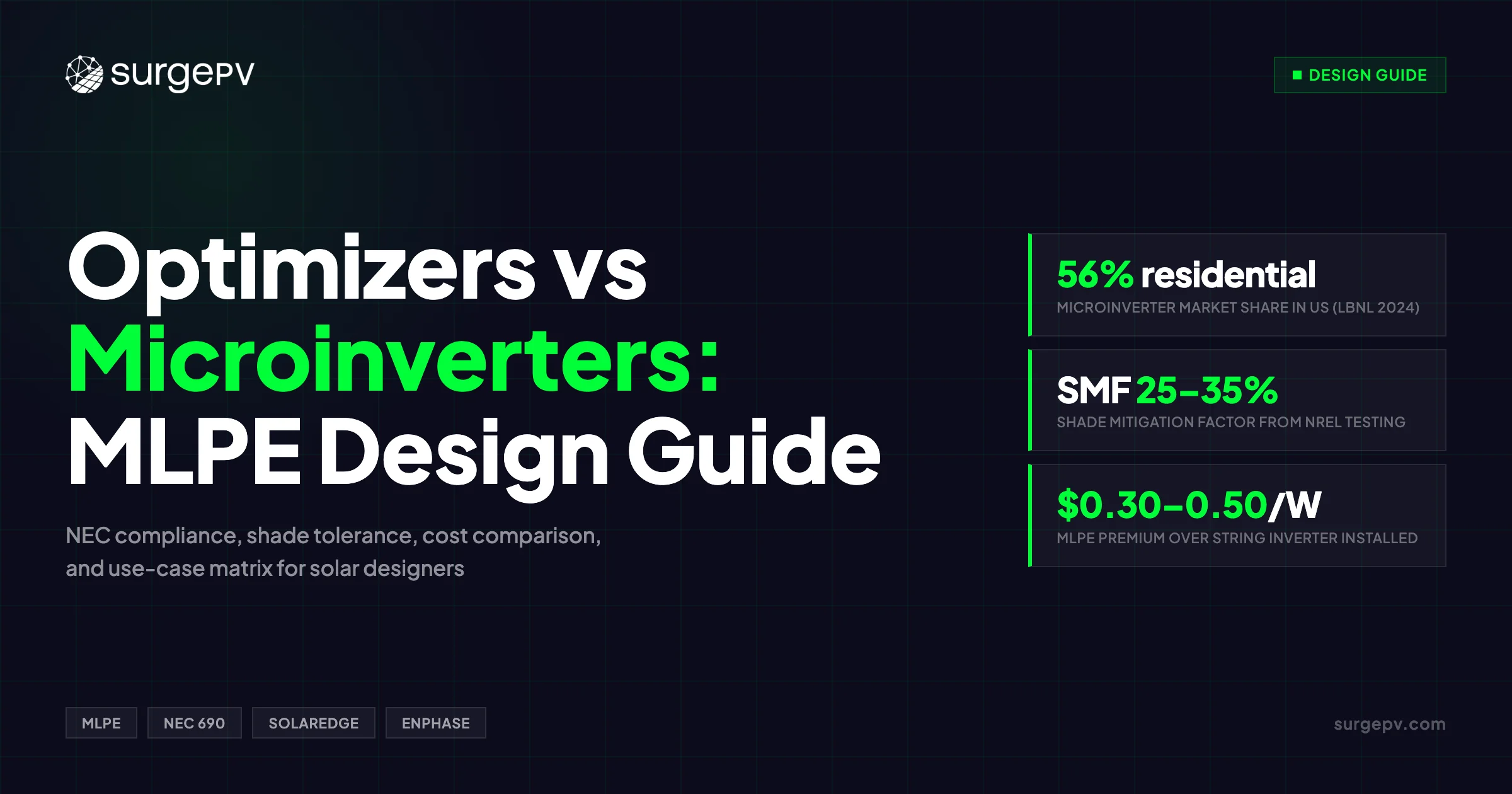
The US residential solar market reached approximately 90% MLPE adoption by 2019, and that figure has held steady. What shifted since then is the split within MLPE: microinverter share climbed from 33% to 56% between 2019 and 2024, per LBNL Tracking the Sun 2024. That has direct consequences for NEC 690.11 arc-fault protection and NEC 690.12 rapid shutdown.
The US residential solar market reached approximately 90% MLPE adoption by 2019, and that figure has held steady. What shifted since then is the split within MLPE: microinverter share climbed from 33% to 56% between 2019 and 2024, per LBNL Tracking the Sun 2024. Optimizers didn’t disappear — they migrated toward commercial and battery-integrated systems where centralized architecture makes sense.
For a solar designer, the choice between DC power optimizers and microinverters is not primarily a cost decision. It is a design architecture decision. It determines how you size conductors, how you satisfy NEC 690.12 rapid shutdown, how you handle shade, and how you quote expansion when a customer wants to add panels in year 3. This guide covers every one of those factors with real numbers.
TL;DR
DC optimizers and microinverters both deliver per-panel MPPT, but their architecture diverges at every point in the design workflow. Microinverter share in US residential grew from 33% to 56% between 2019 and 2024 (LBNL Tracking the Sun 2024). Pick technology based on shade profile, battery plans, roof complexity, and code edition — not just $/W.
What you’ll learn in this guide:
- How each MLPE architecture converts power at the module level
- How NEC 690 string-sizing rules differ between optimizers and microinverters
- What the NREL Shade Mitigation Factor data actually says about shade recovery
- The rapid shutdown compliance path for each technology under NEC 690.12
- Installed cost breakdown — $/W for optimizers, microinverters, and string inverters
- Which technology fits which project type, with a decision matrix
- The most common design mistakes when switching from string inverters to MLPE
Good solar design software accounts for MLPE architecture from the start — string sizing rules, voltage calculations, and shade modeling all differ based on which technology you specify.
How MLPE Works: Two Different Approaches
Module-level power electronics is the category. DC power optimizers and microinverters are two distinct implementations with fundamentally different conversion paths.
DC Power Optimizers (SolarEdge Architecture)
A DC power optimizer mounts behind each panel and performs DC-DC conversion at the module. It runs individual MPPT per panel, then outputs a conditioned DC voltage to the string. A central string inverter at the end of the string handles the final DC-to-AC conversion.
The optimizer’s core function is maintaining a fixed voltage window on the string regardless of what individual panels are doing. SolarEdge optimizers report 99.5% efficiency on their datasheets; the SolarEdge Home Hub central inverter reaches up to 99% CEC weighted efficiency.
The design implication: high-voltage DC — typically 300–600V, up to 1,500V in commercial systems — travels from each optimizer across the roof to the central inverter. This DC voltage is present any time panels produce power. That has direct consequences for NEC 690.11 arc-fault protection and NEC 690.12 rapid shutdown.
Microinverters (Enphase Architecture)
A microinverter mounts behind each panel and performs full DC-to-AC inversion at the module. The panel’s DC output is converted to 240V AC right at the module itself. AC power from each microinverter flows through a trunk cable to a combiner, then to the main panel.
Each panel is a fully independent AC power source. There is no string — panels connect in parallel on the AC side. The Enphase IQ8 series reaches 97.7% peak efficiency and 97% CEC weighted efficiency.
The design implication: the roof carries only AC power. No high-voltage DC exists on the roof at any point. That single fact changes the NEC 690.11 AFCI requirement, the NEC 690.12 RSD requirement, and conductor sizing rules for the entire system.
String Sizing and NEC 690 Design Differences
This is where the two architectures diverge most sharply for designers. The NEC calculation paths are genuinely different.
Optimizer String Sizing Rules
SolarEdge string sizing is governed by two constraints: (1) maximum STC power per string for the specific central inverter, and (2) minimum and maximum string lengths defined by inverter MPPT voltage range and optimizer compatibility.
A physical limit often missed: total cable length from the DC+ terminal of the farthest optimizer to the DC− terminal of the central inverter cannot exceed 1,000 feet (300m). On large roof planes, this constraint can force you to add a second inverter or reposition the existing one.
Conductor sizing follows NEC 690.8(A)(1)(d) — DC-DC converter output circuits. You size conductors based on the optimizer’s listed output current, not the module short-circuit current (Isc). This matters when module Isc and optimizer listed output current differ significantly.
Temperature derating still applies to DC conductor calculations per NEC 310.15(B)(1)(1). Rooftop conduit installations typically require significant temperature adders above ambient — verify the specific adder against local AHJ guidance.
Microinverter Circuit Sizing
Microinverter systems have no string sizing step. The parallel AC architecture eliminates series voltage calculations entirely.
Branch circuit sizing uses NEC 690.8(A)(1)(e) — the microinverter’s listed maximum output current (typically 15A per micro), regardless of what the panel produces at STC. Inverter loading ratio is calculated per panel-inverter pair rather than across a string.
The primary cable concern on an Enphase system is AC voltage drop from the roof junction boxes to the main panel. Because you’re running 240V AC rather than 300–600V DC, voltage drop becomes significant on long horizontal runs. Many installers split panels across multiple junction boxes to keep AC runs short. Target no more than 3% total voltage drop across the AC homerun.
Design calculation comparison:
| Design Variable | DC Optimizer (SolarEdge) | Microinverter (Enphase) |
|---|---|---|
| String sizing | Min/max module count per inverter spec | No strings — parallel AC |
| Conductor sizing rule | NEC 690.8(A)(1)(d): optimizer listed output current | NEC 690.8(A)(1)(e): micro listed output current |
| Max cable run constraint | 1,000 ft DC+ to DC− | AC run limited by voltage drop |
| Voltage calculation | DC string voltage with temperature derate | No DC string voltage calc required |
| AFCI required? | Yes — NEC 690.11 applies (≥80V DC) | No — DC stays below 80V at module |
| RSD hardware | SafeDC optimizer-integrated | Inherent — AC disconnect at service entrance |
Pro Tip
Confirm which NEC edition your AHJ has adopted before designing any MLPE system. Several jurisdictions still enforce NEC 2014, while most now require NEC 2017 or 2020. Using the wrong edition is the most common cause of permit rejection on MLPE projects.
Shade Tolerance: What the NREL Data Actually Shows
Most articles on this topic say “MLPE helps with shading” without citing actual numbers. NREL TP-5J00-62471 (2016) provides real Shade Mitigation Factor (SMF) values.
NREL tested optimizer and microinverter systems side by side using a normalized SMF methodology that corrected an earlier 2012 analysis that overstated performance by 15–20 percentage points. The updated results:
- 2-string system: SMF values in the 25% range for both optimizer and microinverter configurations — essentially matched
- 3-string system: Average SMF = 35%
NREL’s own conclusion: “The major difference between trials was the number of parallel strings, not differences between equipment tested.” Whether you use Enphase or SolarEdge matters less than how many parallel strings (or microinverter branches) you design into the system.
A 2020 ZHAW indoor laboratory study adds useful data: in unshaded conditions, an MLPE system yielded approximately 2.82% less energy than a string inverter due to conversion losses. In heavy shading orthogonal to cell strings, the MLPE system yielded approximately 3.5% more energy than the string system.
Practical implication: MLPE’s shade advantage is real but bounded. It pays for itself in medium-to-heavy shade. On a clean, south-facing unshaded roof, a good string inverter outperforms MLPE on both yield and cost.
Partial shade performance comparison:
| Condition | DC Optimizers | Microinverters | String Inverter |
|---|---|---|---|
| Optimal (no shade) | 97.3% | 97.0% | 96.5% |
| Partial shading | 92.1% | 93.5% | 78.2% |
| Mixed orientations | 94.8% | 95.2% | 84.1% |
| Panel mismatch | 95.5% | 96.8% | 87.3% |
Microinverters show a 3–5% advantage over DC optimizers in heavily shaded conditions per independent testing. In mixed-orientation roofs, the gap is similar. When shade is the dominant site factor, microinverters are the better pick. When shade is absent, the difference between optimizer and microinverter yield is within 0.5%.
Use SurgePV’s shadow analysis tool to model site-specific shading before specifying MLPE technology. The difference between a 15% annual shade loss site and a 5% site determines whether a $0.20–$0.30/W microinverter premium is justified. For a direct comparison, see Arka 360 vs SurgePV.
Key Takeaway
NREL data shows optimizers and microinverters deliver nearly identical shade recovery — SMF values range from 25% to 35% depending on system configuration, with only slight equipment differences between platforms. The microinverter advantage appears primarily in the most heavily shaded configurations. Don’t over-specify microinverters on lightly shaded sites.
Rapid Shutdown Compliance (NEC 690.12)
NEC 690.12 rapid shutdown requirements have tightened with each code cycle. The 2017 NEC requires module-level RSD: voltage within the array boundary must drop to 80V or below within 30 seconds of RSD initiation.
SolarEdge SafeDC
SolarEdge’s SafeDC technology reduces each optimizer’s output to below 1V when RSD is triggered. String voltage drops to one volt per module (e.g., 30 modules = 30V), well below the 80V threshold.
SafeDC is initiated by the AC disconnect, inverter shutdown, or a dedicated DC disconnect. The technology is proprietary: it requires a matched SolarEdge central inverter to function. Pairing SolarEdge optimizers with a third-party inverter breaks the RSD signaling entirely. Read AC Disconnect Sizing for Solar for a complete walkthrough.
Enphase Inherent Compliance
Microinverter systems comply with NEC 690.12 by design. No high-voltage DC exists on the roof, so there is nothing to shut down at the module level. When grid power disconnects, microinverters stop producing AC power within IEEE 1547 anti-islanding requirements.
An AC disconnect at the service entrance satisfies NEC 690.12 for Enphase systems. No additional RSD hardware is required or permitted.
NEC 690.56(C) labeling is required on both platforms — RSD labels must appear on the rapid shutdown switch and all applicable enclosures.
Common permit rejection reasons for MLPE systems:
- Incompatible equipment pairing (optimizer + non-SolarEdge inverter with missing RSD signaling)
- Designing to NEC 2014 when the AHJ requires 2017 or 2020
- Missing NEC 690.56(C) RSD labels
- No array boundary designation on the single-line diagram
- No documentation of RSD functionality verification method
Safety: Arc Fault, DC Voltage, and Roof-Level Risk
NEC 690.11 requires arc-fault circuit interrupter (AFCI) protection for PV systems with DC source or output circuits operating at 80V DC or higher.
Enphase microinverter systems operate below 80V DC at the module at all times. NEC 690.11 does not apply. No AFCI hardware is required. This holds as long as individual microinverters are paired one-to-one with panels.
SolarEdge and other optimizer systems maintain high-voltage DC (300–600V+) between the optimizer outputs and the central inverter. NEC 690.11 applies. AFCI protection is required — it is typically integrated into the SolarEdge central inverter.
DC arc faults are the primary cause of solar-related fires. DC arcs do not self-extinguish at voltage zero-crossings the way AC arcs do. AC arcs at 240V are inherently less persistent. This is part of why microinverter architecture is specified in fire-risk jurisdictions.
Roof-level voltage by architecture:
| Architecture | Roof Voltage Type | Typical Level | AFCI Required? |
|---|---|---|---|
| Microinverter | AC only | ~240V | No |
| DC optimizer + string inverter | DC | 300–600V+ | Yes (NEC 690.11) |
| Standard string inverter | DC | 300–600V+ | Yes (NEC 690.11) |
Temperature ratings: Enphase IQ8 microinverters are rated to 60°C ambient — rooftop temperatures in hot climates regularly approach this in summer. SolarEdge optimizers are rated to 85°C; the central inverter is wall-mounted and avoids peak rooftop heat exposure. Both carry IEC 62109-1/-2 and UL 1741 certification.
Cost Comparison: Optimizers vs Microinverters vs String
The $/W premium for MLPE is real, and it differs between optimizer and microinverter systems.
Installed cost by system type (2024–2025):
| System Type | $/W Installed | 10kW System Total |
|---|---|---|
| String inverter only | $2.04–$2.63 | $20,400–$26,300 |
| DC optimizer (SolarEdge) | $2.40–$2.80 | $24,000–$28,000 |
| Microinverter (Enphase) | $2.40–$2.96 | $24,000–$29,600 |
MLPE premium over string:
- DC optimizers: $0.30–$0.50/W — approximately $1,800–$2,600 additional on a 7kW system
- Microinverters: $0.50–$0.80/W — approximately $2,500–$4,000 additional on a 7kW system
Per-unit wholesale costs for reference:
- Enphase IQ8+: $140–$160/unit
- SolarEdge P505 optimizer: ~$85/unit; SolarEdge central inverter adds $1,200–$1,500
On a 25-panel 10kW system, optimizer equipment costs approximately $9,850 (25 × $85 + $1,500 inverter). Microinverters run approximately $12,900 (25 × $160 + Envoy gateway). Installed labor difference is modest — both require per-panel roof work plus inverter or gateway wiring.
Warranty economics: SolarEdge’s standard inverter warranty is 12 years, extendable to 20–25 years at added cost. Enphase’s standard warranty is 25 years, included. A 25-year system life analysis for SolarEdge must account for inverter replacement risk in years 12–15. Enphase removes that uncertainty.
Use SurgePV’s generation and financial tool to model the true cost-benefit of MLPE upgrades — including yield gains from shade recovery and warranty risk adjustments across a 25-year horizon.
For battery-integrated systems: SolarEdge DC-coupled battery storage (Energy Bank) avoids one conversion step versus Enphase AC-coupled storage (IQ Battery). DC coupling improves round-trip efficiency, which matters in systems with daily cycling. If a battery is in scope, the optimizer platform has an efficiency edge. For more on this topic, see AC Coupled vs DC Coupled Battery Solar.
Monitoring Capabilities
Both platforms deliver panel-level monitoring at 15-minute intervals. The differentiation is in how that data is presented and who it’s designed for.
SolarEdge mySolarEdge: Technical platform. Installers get bulk system configuration, downloadable AC current, AC power, DC voltage, and frequency data, fleet management across multiple sites, and peer-group performance benchmarking. Remote diagnostics identify communication pathway issues, component problems, and configuration errors.
Enphase Enlighten: Consumer-friendly platform. Color-gradient panel performance maps, mobile-first interface, social sharing features, and energy management integration. Installer fleet view is available through a separate login. Per-panel under-performance warnings catch failures before production losses compound.
Platform lock-in is real: both systems require manufacturer-specific hardware to access panel-level data. Third-party monitoring options exist but lose granularity below the string level.
Specify SolarEdge monitoring for technically engaged customers running fleet operations. Specify Enphase for homeowner-facing systems where app simplicity is a selling point.
When to Specify Each Technology
The right choice is almost always clear once you know the shade profile, battery requirement, and expansion expectation.
Decision matrix:
| Project Scenario | Best Choice | Primary Reason |
|---|---|---|
| Complex multi-orientation roof | Microinverter | Independent MPPT per panel; no string compromise |
| Partial shading (trees, chimneys) | Microinverter | SMF 23–35% shade recovery; no single-string drag |
| Future expansion planned | Microinverter | Add panels one at a time; 1 IQ Gateway supports 300 IQ Series micros |
| DC-coupled battery storage | Optimizer | SolarEdge Energy Bank: direct DC charging, better round-trip efficiency |
| EV charger integration | Optimizer | SolarEdge Energy Hub with integrated EV charger |
| Budget-constrained residential | Optimizer | $0.20–$0.30/W lower installed cost |
| Large unshaded ground mount | String inverter | MLPE overhead not justified; string economics dominate |
| Safety-priority jurisdiction | Microinverter | No high-voltage DC on roof; AFCI exemption |
| Commercial with central maintenance | Optimizer | Single inverter service point; commercial optimizer models available |
| 25-year warranty without paid extension | Microinverter | Enphase standard 25yr; SolarEdge requires paid extension |
Design MLPE Systems Faster
SurgePV handles optimizer string sizing, NEC compliance checks, and shade simulation in one workflow — so you spend less time on calculations and more time closing projects.
Book a DemoNo commitment required · 20 minutes · Live project walkthrough
Common Design Mistakes to Avoid
Switching from string inverters to MLPE introduces a specific set of failure modes. Most come from applying string-inverter assumptions to a different architecture.
SolarEdge Optimizer Mistakes
- Ignoring central inverter DC input limits. Adding panels to an existing system without checking whether the central inverter has headroom. Exceeding the inverter’s maximum DC input power may require a full replacement.
- Exceeding the 1,000 ft cable run limit. Total cable from the DC+ terminal of the farthest optimizer to the DC− terminal of the central inverter must stay within 1,000 feet (300m). Large roof planes can violate this without careful layout.
- Optimizer-module power mismatch. Pairing the wrong optimizer model (P300, P404, P485, P505) with a panel whose STC wattage or Vmp falls outside the optimizer’s input range.
- Using residential optimizers on commercial three-phase inverters. Commercial SolarEdge inverters require commercial-grade optimizer models. Residential optimizers are not compatible.
- Third-party inverter RSD failure. SolarEdge optimizers paired with non-SolarEdge inverters lose SafeDC RSD signaling entirely. The system will fail permit inspection in any NEC 2017+ jurisdiction.
Enphase Microinverter Mistakes
- AC voltage drop neglect. Long AC homeruns from roof junction boxes to the main panel at 240V drop voltage faster than equivalent DC runs at 300–600V. Designers who apply DC voltage drop intuitions to AC systems routinely undersize conductors.
- Panel wattage exceeding microinverter AC output rating. Pairing a 480W panel with a microinverter rated at 295W AC output creates clipping and reduces system yield below projections.
- Undersizing trunk cable for cumulative current. The trunk cable from a branch of microinverters carries the sum of all micro outputs. On a 10-unit branch at 1.21A each, that’s 12.1A — plus the 125% overcurrent protection factor, you need a 20A circuit.
- Poor IQ Gateway placement. The IQ Gateway requires reliable network connectivity. Poor Wi-Fi signal or ethernet routing creates monitoring gaps and affects firmware update reliability.
General MLPE Mistakes
- NEC edition mismatch. Designing to NEC 2014 when the AHJ has adopted NEC 2017 or 2020.
- Missing NEC 690.56(C) labeling. Both platforms require rapid shutdown labels on the switch and applicable enclosures. Missing labels are the single most common permit correction on MLPE projects.
- Applying module Isc for optimizer circuit sizing. NEC 690.8(A)(1)(d) specifies the optimizer’s listed output current — not the module Isc — as the basis for DC output circuit conductor sizing.
- Forgetting temperature adders. Voltage calculations require +35°C for modules with less than 6” standoff, +30°C for standard rack mount. Skipping this step causes conductors to pass at STC but fail at operating temperature.
- Mixing incompatible panel types on one optimizer string. Different module types have different Vmp and Imp characteristics. Mixing them on a string creates optimizer configuration conflicts.
Pro Tip
Before submitting any MLPE design for permit, verify three things: (1) the NEC edition your AHJ has adopted, (2) that your inverter and optimizer or microinverter models are listed together on the manufacturer’s compatibility matrix, and (3) that all NEC 690.56(C) labels are called out explicitly on the single-line diagram.
Conclusion
DC power optimizers and microinverters both deliver module-level MPPT. But they are different systems with different design workflows, different NEC compliance paths, and different total cost structures.
Three actions before specifying MLPE on your next project:
- Model the shade first. Use SurgePV’s shadow analysis to quantify shade loss at the specific site. If annual shade loss is below 5%, the yield difference between optimizer, microinverter, and string inverter is within measurement noise. MLPE is harder to justify at that threshold.
- Confirm the NEC edition and AHJ requirements. RSD, AFCI, labeling, and conductor sizing rules all depend on which code edition is enforced locally. This step takes 10 minutes and prevents permit rejections.
- Factor in the full 25-year economics. The solar software your team uses should model system lifetime costs — including inverter replacement risk for SolarEdge systems and the AC-coupling efficiency penalty for Enphase battery storage. Present these numbers clearly in your proposals using solar proposal software so the MLPE technology decision is transparent, not assumed.
The microinverter share shift from 33% to 56% in US residential since 2019 reflects real installer and homeowner preferences — 25-year warranties, simpler expansion, and no high-voltage DC on the roof. For shaded, complex, or expansion-likely residential projects, microinverters win on every non-cost metric. For battery-integrated, large commercial, or cost-constrained residential designs, optimizers remain competitive.
Frequently Asked Questions
Are microinverters worth the extra cost?
For shaded or complex roofs, yes. Microinverters recover 23–35% of shading losses per NREL TP-5J00-62471, come with a 25-year standard warranty, and eliminate high-voltage DC on the roof. For large unshaded arrays where cost is the priority, DC optimizers deliver comparable yield at $0.20–$0.30/W lower installed cost.
Do microinverters need rapid shutdown devices?
No. Microinverter systems produce only low-voltage AC at the module — no high-voltage DC is present on the roof. An AC disconnect at the service entrance satisfies NEC 690.12. NEC 690.56(C) labeling is still required on all MLPE systems.
Which is better for battery storage — optimizers or microinverters?
DC optimizers with a SolarEdge Energy Hub inverter allow DC-coupled battery storage, which avoids a conversion step and improves round-trip efficiency. Enphase microinverter systems use AC-coupled storage (Enphase IQ Battery), which adds one conversion stage. For battery-first designs, optimizer systems generally have an efficiency edge.
What happens if one microinverter fails?
Only the panel connected to that microinverter stops producing power. The rest of the system runs normally. In a SolarEdge optimizer system, a failed central inverter stops the entire array — though failed individual optimizers have less impact since other optimizers continue operating.
Can I expand my system later with power optimizers?
Yes, but with limits. Each SolarEdge central inverter has a maximum DC input capacity. Adding panels beyond that limit requires a second inverter or a full inverter replacement. Enphase systems are more flexible — one IQ Gateway supports up to 300 IQ Series microinverters, and you add panels one at a time.