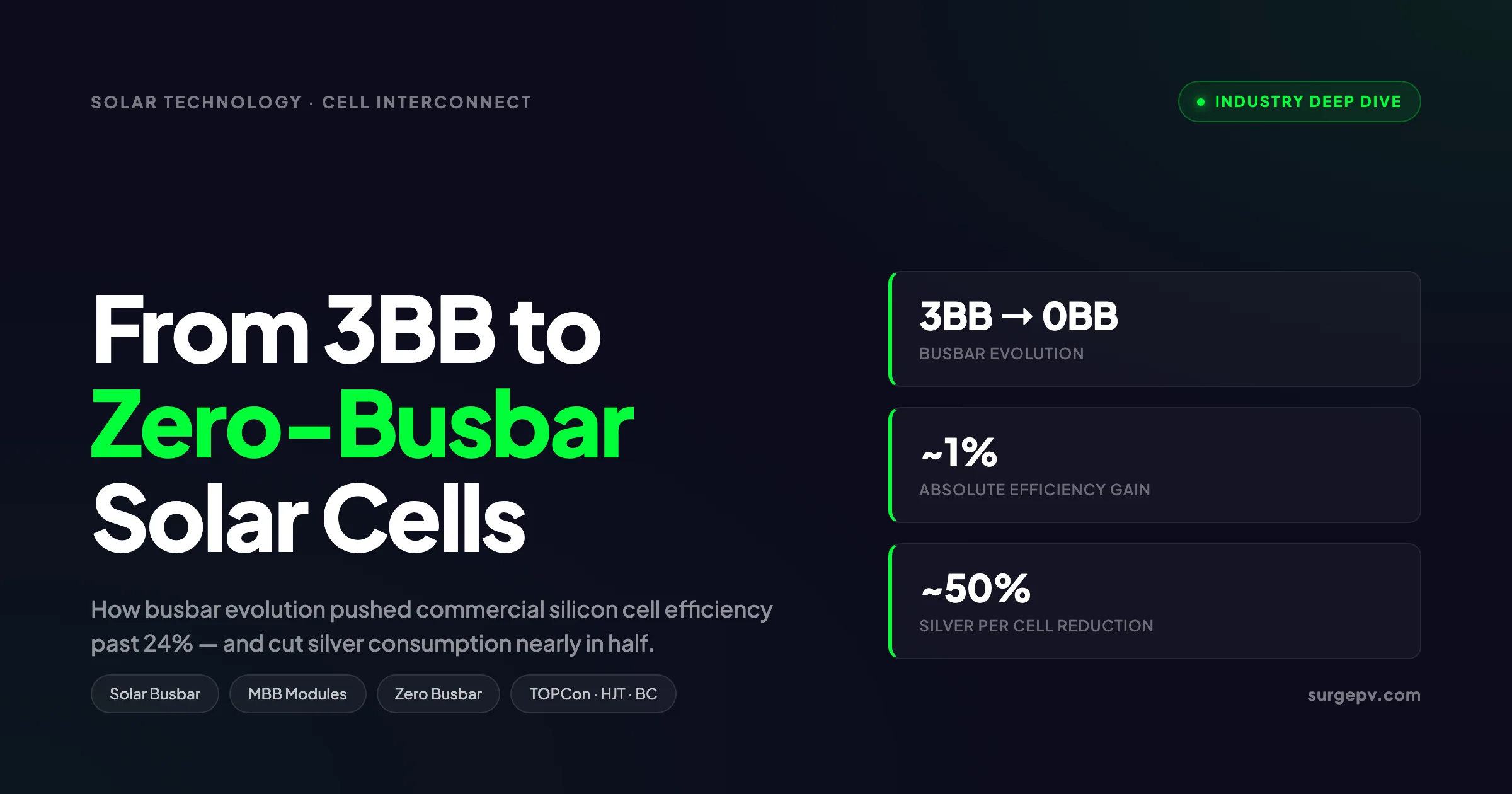
In 2015, a typical silicon solar cell had three thick silver busbars running across its front face. In 2026, the best cells have none.
That progression — 3BB to 5BB to 9BB to 12BB to 16BB to zero busbar — is one of the cleanest examples in the solar industry of cell-level engineering driving module-level performance. Each step recovered a fraction of a percent of efficiency, cut silver consumption, and changed how stringer machines on the factory floor are built.
This guide walks through the full evolution: what busbars do, why design choices changed every two or three years, and how 0BB modules now push commercial cell efficiency past 24%. It is aimed at engineers and procurement teams choosing modules for projects designed in solar design software and built in the field by EPC crews.
Quick Answer
Busbars are the metal strips on a solar cell that collect current from the finger lines and pass it to neighbouring cells. Solar cell busbar technology evolved from 2-3 wide bars (pre-2016) to 9-16 thin round wires (2018-2023) to zero-busbar designs (2024 onward), driven by the trade-off between shading losses (more bars = more shadow) and series resistance losses (more bars = lower I²R). The current state of the art uses 0BB interconnects with copper ribbons bonded to a dense pad matrix on TOPCon, HJT, and back-contact cells. Compared to 3BB, the latest 0BB designs deliver about 1% absolute efficiency gain and roughly 50% less silver per cell.
Read Solar Shading Analysis Guide for a complete walkthrough.
What this guide covers:
- What busbars are and what job they do on a solar cell
- The full evolution from 2BB through 0BB with dates and dominant cell architectures
- The shading vs resistance trade-off that drove every busbar count change
- Multi-busbar (MBB) and super-multi-busbar (SMBB) technology
- Zero busbar (0BB) and SmartWire interconnects in detail
- Silver consumption and bill-of-materials math
- Field reliability, microcrack tolerance, and IEC test data
- Manufacturer-by-manufacturer adoption status in 2026
- Why more busbars are not always better
- How busbar choice shows up in module datasheets Shadow analysis software identifies shading issues before installation.
What Busbars Are and Why They Matter on a Solar Cell
A silicon solar cell generates electrons when sunlight strikes the wafer. Those electrons have to travel out of the cell to be useful. The metal grid on top of the cell is the highway system that collects them.
The grid has two parts. Fingers are very thin silver lines, usually 30 to 50 microns wide, printed across the cell in parallel. They sit close together (about 1.4 mm apart on a modern cell) and collect electrons from the silicon directly underneath. Busbars run perpendicular to the fingers. They collect current from the fingers and route it off the cell through a soldered ribbon to the next cell in the string.
So every cell has two competing design pressures.
Shading pressure. Every square millimeter of silver on the front of the cell blocks light. Light that does not reach the silicon does not become electricity. A 3BB cell with 1.5 mm wide busbars covers about 4% of the front surface in metal. That is 4% of the cell area producing zero current.
Resistive pressure. Every electron has to travel along a finger until it reaches a busbar. The longer the trip, the more energy is lost as heat (I²R loss). With only 3 busbars on a 156 mm cell, the average electron travels about 13 mm along a finger before reaching a busbar. With 16 busbars, that distance drops to about 2.4 mm. Less resistance means more power output.
Busbar design is the answer to: “how do we collect current efficiently without shading the cell?” Every generation of busbar technology is a different point on that trade-off curve.
For a deeper definition of the basic component, see our busbar glossary entry.
The Full Evolution Timeline: 2BB to 0BB
Below is the busbar progression that ran in roughly two-year cycles between 2010 and 2026.
| Era | Dominant busbar count | Dominant cell type | Approximate front silver coverage |
|---|---|---|---|
| 2010-2014 | 2BB | Aluminium-BSF mono and multi | 3.5% |
| 2014-2017 | 3BB | Aluminium-BSF, early PERC | 4.0% |
| 2017-2019 | 4BB and 5BB | PERC | 3.5% |
| 2019-2021 | 9BB | PERC half-cut | 2.2% |
| 2021-2023 | 12BB and 16BB (MBB) | TOPCon and HJT | 1.5-1.8% |
| 2023-2025 | 16BB to 22BB (SMBB) | TOPCon | 1.3% |
| 2024-2026 | 0BB (zero busbar) | HJT, TOPCon, BC | under 1% (pads only) |
Two things stand out from the table. First, the count went up rapidly between 2017 and 2023, then jumped to zero. Second, the silver coverage on the front fell roughly in half over the period, even though average cell efficiency rose from about 18% to over 24%.
The shift was not gradual at every stage. The move from 5BB to 9BB in 2019 was a hard cutover for most Tier 1 manufacturers. The move from 16BB to 0BB starting in 2024 has been similar — premium production lines are switching in single shutdowns, not phasing busbars in one by one.
The 3BB Era (2014 to 2017)
Three-busbar cells dominated the industry for most of the early PERC era. The bars were flat soldered ribbons about 1.5 mm wide, made of tinned copper with a silver paste contact layer on the cell side.
Three bars worked because cell currents were modest. A 156 mm aluminium-BSF cell at 18% efficiency produced roughly 8.7 A short-circuit current. The fingers were thick enough (around 60 microns wide, 15 microns tall) to carry that current to a nearby busbar without heating up.
Module power for a 60-cell 3BB module of this era was 260 to 285 W. By today’s standards that is low, but it set the cost benchmark that everything since has had to beat.
The 5BB Bridge (2017 to 2019)
Adding two more busbars cut the average finger-travel distance by 40%. The benefit was straightforward: roughly 0.2 to 0.3% absolute efficiency, recovered mostly from fill factor improvements. The busbar width stayed similar, so shading rose slightly, but the resistance saving was larger.
5BB was a step on the road. It did not survive long because larger wafers (M6 at 166 mm, then M10 at 182 mm) pushed cell currents up further and demanded more busbars.
MBB (Multi-Busbar) Revolution: 9BB to 12BB (2019 to 2022)
The jump from 5BB to 9BB was the real turning point. It coincided with two other industry shifts: the move from flat ribbon to round wire, and the adoption of half-cut cells.
Round wire matters because a round cross-section has a lower silhouette than a flat ribbon of equivalent conductance. A 0.3 mm round wire covers 0.3 mm of cell width when viewed from above, but the rounded top scatters some incident light back into the encapsulant, where it can reflect off the back glass or backsheet and re-enter the cell. The effective optical shading from round wire is about 50 to 60% of the geometric shading.
Half-cut cells doubled the number of strings inside a module from 3 to 6, which cut the current per string by half. Lower current means lower I²R loss in the ribbon and the junction box. Combined with 9BB on each half-cell, the effective finger-travel distance dropped to about 4 mm.
Manufacturers also moved away from soldered ribbon to low-temperature electrically conductive adhesive (ECA) for some HJT cells in this era, because soldering temperatures of 230°C+ damage the amorphous silicon layers on HJT.
Super Multi-Busbar (SMBB): 16BB and Above (2022 to 2024)
By 2022, JA Solar, JinkoSolar, and LONGi were shipping mainstream TOPCon modules with 16 round-wire busbars. By mid-2023, SMBB technology with 16BB or more dominated new TOPCon production, with industry data showing over 87% of new TOPCon cell lines using SMBB.
The marginal gain from 12BB to 16BB was small in absolute terms, perhaps 0.1% efficiency, but it freed manufacturers to thin the fingers further. Thinner fingers mean less silver, and silver pricing in 2023 (a 30%+ jump from late 2022) made every milligram count.
The diminishing returns of adding more busbars set up the industry for the next leap: stop adding busbars and remove them entirely.
Zero Busbar (0BB): 2024 to Present
0BB cells have no front-side busbars at all. Instead, the cell has a dense matrix of small silver pads — sometimes called “drops” or “pads” — printed along the locations where the finger lines run. Round copper wires (typically 18 to 24 wires per cell) are bonded directly to these pads during stringing.
The wires perform two jobs at once: they collect current from the fingers (replacing the busbar function) and interconnect the cell to its neighbours (replacing the tabbing ribbon function). There is no separate busbar.
This is the structural change that gives 0BB its efficiency bump. The pads cover well under 1% of the cell area, compared to 1.3-1.8% for 16BB. The wires themselves block some light, but they are placed where the fingers used to be, and the optical shading of round wire is only about half its geometric width.
The cumulative gain from 16BB to 0BB on a TOPCon cell is about 0.3 to 0.5% absolute efficiency. On HJT cells, where front-side silver loading was higher to begin with, the gain is closer to 0.7 to 1.0%.
Why Solar Cell Busbar Technology Matters Past the 24% Efficiency Threshold
Once mainstream commercial cell efficiency crossed 23% in 2022, every remaining tenth of a percent became hard to find. The big architectural moves — PERC, PERC+, TOPCon, HJT — had already happened. Squeezing more out of the cell meant looking at the metallisation grid.
A 24% efficient cell that loses 1% absolute to busbar shading is effectively a 25% cell with a shadow on it. Removing that shadow is “free” efficiency in the sense that the silicon, the passivation layer, and the cell architecture are already paid for. The only cost is changing the stringer machine and the silver paste pattern.
Three numbers explain why the industry chased 0BB:
- 5-8 W more per module on a 600 W bifacial design at zero silicon cost
- 30-50% less silver per cell, which at 2025 silver prices means about 1.5 cents per cell or roughly $1.30 per module
- 20-30% lower failure rate in 85°C/85% humidity damp-heat tests, which feeds directly into module warranty terms
For an installer running large-scale projects, 5 W per module across a 1 MW plant means 8 to 10 extra kW of nameplate capacity, which generates an extra 12 to 15 MWh per year in a typical European or Indian solar resource. Running the financial model in our generation and financial tool shows that kind of gain shifts the payback period by about a month on most utility-scale projects. Also see: Best Solar Design Software India. Also see: European Solar Incentives.
The Shading vs Resistance Trade-Off: Why More Busbars Isn’t Automatically Better
This is the contrarian section. Industry messaging often treats “more busbars = better module” as a rule of thumb. It is not.
The number of busbars is the solution to an optimisation problem with two competing terms.
Term 1: Shading loss. Every additional busbar adds metal area on the front of the cell. If each busbar has width w and length L, and there are n busbars on a cell of area A, the shading fraction is:
S = (n × w × L) / A
For a 182 mm M10 cell with 0.3 mm round wires (effective optical width 0.15 mm) and a 16BB layout, S is about 1.3%.
Term 2: Resistive loss. Current generated in a finger has to travel an average distance of (L_finger / 2n) to reach a busbar. The power loss in the fingers is proportional to that distance squared:
P_finger ∝ ρ × J² × (L_finger / 2n)²
Where ρ is the finger sheet resistance and J is the current density. Doubling n cuts this loss by a factor of four.
The total loss is shading + resistive. Plot it as a function of n and you get a U-shaped curve. The minimum sits at the optimum number of busbars.
| Busbar count (n) | Shading loss | Resistive loss (finger) | Total loss |
|---|---|---|---|
| 3 | 0.7% | 1.40% | 2.10% |
| 5 | 1.0% | 0.50% | 1.50% |
| 9 | 1.4% | 0.16% | 1.56% |
| 12 | 1.5% | 0.09% | 1.59% |
| 16 | 1.3% (thinner wires) | 0.05% | 1.35% |
| 0BB (with 18 wires) | 0.9% | 0.04% | 0.94% |
Two things to notice. First, going from 3BB to 9BB cuts resistive loss by an order of magnitude. Second, going from 9BB to 12BB barely moves the total — shading and resistance roughly balance out.
The reason 16BB and SMBB still happened was not pure resistance reduction. It was that thinner busbars (made possible by having more of them) could be used with thinner fingers and less silver. The optimisation target was not just efficiency, but efficiency at lowest silver cost.
And the reason 0BB jumped past 16BB was not adding more bars, it was removing them entirely and accepting a different geometry — pads instead of strips.
So “more busbars” was right for a long time. Now “no busbars” is right. The underlying question is: what minimises total electrical and optical loss while keeping silver paste consumption low?
Pro Tip
When comparing modules from different manufacturers on the same datasheet, do not just look at busbar count as a quality marker. A well-designed 16BB SMBB TOPCon module can have lower shading and similar efficiency to a poorly-implemented 0BB design from a less mature line. Look at the actual efficiency, fill factor, and bifaciality factor numbers on the IEC 61215 test report.
Read Bifacial Solar Panel Design Guide for a complete walkthrough.
Multi-Busbar Technology in Detail
MBB technology came in two main flavours: 9BB flat ribbon and 9-12BB round wire. The round wire version became the dominant production approach.
Round Wire vs Flat Ribbon
Flat ribbon is essentially a small copper strip with a tin-silver coating, soldered to the busbar pad on the cell. It has been used since the 1980s in silicon solar cells. It is reliable and inexpensive, but the flat top is fully optically opaque to incident light.
Round wire is a copper wire (typically 0.25 to 0.35 mm diameter) with the same Sn-Ag coating. Because of its round profile, some light striking the wire reflects off the curved surface, hits the glass at an angle below the critical angle for total internal reflection, and bounces back down onto the cell. This is the “secondary light” or “geometric gain” of round wire, and it recovers about 40 to 50% of the geometric shading.
A 0.3 mm round wire blocks 0.3 mm of cell width geometrically but loses only about 0.15 to 0.18 mm of effective generation. That is why a 12-round-wire MBB cell can have similar effective shading to a 5BB flat-ribbon cell despite using more than twice as many busbars.
Silver Paste Pattern Changes
Moving from 5BB to 9BB-12BB MBB meant redesigning the screen-printed silver pattern on the cell. The busbar widths dropped from ~1.5 mm flat to ~0.3-0.4 mm round wire pads. The pads themselves became dotted (small discrete pads under each wire intersection point) rather than continuous strips, cutting silver consumption another 15 to 20%.
The fingers also got thinner. A 5BB cell had fingers about 50 microns wide. A 12BB cell has fingers about 30 to 35 microns wide. With more busbars to drain current, each finger carries less, so it can be thinner without overheating.
Half-Cut and Third-Cut Cells
MBB and half-cut cell technology rolled out together because they target the same problem: I²R loss in the cell and the string. Half-cut cells cut a standard M6/M10 cell along its midline using a laser, then assemble the module with the two halves wired as separate strings. Each string carries half the current.
For a 12BB half-cut cell, the effective current path is half a cell width divided by 12 busbars, giving an average finger travel of about 2 mm. Combined with the per-string current halving, total resistive losses inside the module drop by roughly 75% compared to a 5BB full-cell module.
Third-cut (or “triple-cut”) cells, used in some bifacial designs from 2024 onward, push this further, but the gains are marginal in most lighting conditions.
Zero Busbar (0BB) Technology in Detail
0BB is not just “more thin wires.” It is a different way of building the interconnect.
How 0BB Connects to the Cell
On a 0BB cell, the screen-printing step puts down only fingers and a regular array of small silver pads. There is no continuous metal strip. The pads sit at points where the interconnect wires will land later.
During stringing, copper wires (usually 18 to 24 per cell, depending on cell size) are laid across the cell. The wires have a low-melting-point alloy coating (typically Sn-Bi or Sn-In). At the bonding station, infrared or hot-air heating fuses the wire coating to the silver pads. There is no separate soldering of busbars first and tabbing wires second — it happens in one step.
The wires extend off the edge of each cell to connect to the next cell. So each wire performs three jobs:
- Collects current from the fingers underneath it (busbar job)
- Carries current along the wire length (busbar job)
- Hands current off to the next cell at the end of the cell (tabbing ribbon job)
This single-step assembly is faster than separate busbar soldering and tabbing, and it puts less thermal stress on the cell.
SmartWire Connection Technology
Meyer Burger’s SmartWire variant of 0BB is worth describing separately because it works differently. Instead of bonding wires to pads with heat, SmartWire uses an electrically insulating polymer film with copper wires embedded in it. The film is laid across the cell during module lamination. The heat and pressure of lamination melt the wire coating and fuse it to the cell metallisation.
There is no separate stringer step. The cells and the wire film are stacked together and laminated as a single assembly. This works particularly well on HJT cells because the lamination temperature (around 150°C) does not damage the amorphous silicon layers, unlike the 230°C soldering temperatures of conventional stringing.
SmartWire was the first widely-deployed 0BB-style technology, used by Meyer Burger and Hevel Solar from around 2018. Today it competes with direct-bonding 0BB approaches from Chinese manufacturers.
Compare 0BB and MBB modules in your next project design
Load module datasheets directly into SurgePV’s design environment and run side-by-side production estimates for different busbar architectures on the same site.
Book a DemoNo commitment required · 20 minutes · Live project walkthrough
For a direct comparison, see Arka 360 vs SurgePV.
Manufacturing Equipment Changes
0BB cannot run on a stringer designed for flat-ribbon busbars. The wire feed system, the alignment optics, and the bonding head all need to be different.
Tier 1 cell manufacturers have been retooling lines through 2024 and 2025. A new 5 GW 0BB-ready stringer line costs roughly $8 to $12 million per GW, compared to $5 to $7 million per GW for a conventional MBB line. The capex premium pays back in 12 to 18 months on the silver cost saving alone, before counting the efficiency benefit.
Silver Consumption: The Hidden Driver of Busbar Evolution
If efficiency was the only consideration, MBB and 0BB might have come 5 years later. Silver pricing forced the timeline.
Silver is the primary metal in the screen-printed grid on a silicon solar cell. The amount used per cell has been a steady cost concern since the early 2010s. As wafer sizes grew and cell currents rose, silver loading on conventional cells stayed flat or rose slightly — about 80 to 120 mg per cell on a typical 3BB or 5BB PERC line.
The push to thinner fingers, smaller busbars, and ultimately 0BB design has cut silver loading to about 30 to 50 mg per cell on TOPCon 0BB lines and 60 to 80 mg per cell on HJT 0BB lines.
| Cell type | Busbars | Silver loading (mg/cell) | Cost per cell at $30/oz |
|---|---|---|---|
| Multi-Si 3BB | 3 | 130 | $0.138 |
| PERC 5BB | 5 | 100 | $0.106 |
| PERC half-cut 9BB | 9 | 90 | $0.095 |
| TOPCon 12BB | 12 | 90 | $0.095 |
| TOPCon 16BB SMBB | 16 | 70 | $0.074 |
| TOPCon 0BB | 0 | 40 | $0.042 |
| HJT 0BB | 0 | 70 | $0.074 |
The TOPCon 0BB line saves about 9 cents per cell in silver vs PERC 5BB. A 144-half-cell module has 144 cells. That is $13 per module, multiplied across millions of modules per year in a Tier 1 production line.
Silver prices have fluctuated significantly through 2025 and into 2026 (currently trading around $32/oz on the LME), which makes the gap even larger when prices spike.
For context on how this compares against other module trends, see our analysis of TOPCon vs HJT cost trajectories and the broader bifacial solar module guide.
Field Reliability and Microcrack Tolerance
The other big benefit of MBB and 0BB beyond efficiency and silver is reliability.
Microcrack Behaviour
Microcracks happen in cells from a combination of cell-handling stress during manufacturing, lamination pressure, transport vibration, and field thermal cycling. A microcrack can isolate a region of the cell from the busbar grid. The current that would have flowed from that region is lost — either entirely, or until the crack is bypassed by a parallel current path.
With 3BB, a microcrack that isolates a quarter of a cell can lose 25% of that cell’s output. With 12BB, the same crack might isolate only 1/12 of the cell’s collection area, losing 8%. With 0BB and 18 wires across the cell, the loss can be under 5%.
This is why MBB and 0BB modules show better degradation curves over 10-25 year field exposure. The Fraunhofer ISE has published damp-heat cycling data showing 0BB modules degrading about 30% less than equivalent 5BB modules over 2000 hours of 85°C/85% RH testing — the standard accelerated aging condition.
Soldering Stress
Soldering a flat ribbon onto a cell at 230°C creates a thermal mismatch when the assembly cools. The ribbon contracts more than the silicon. The result is residual stress in the cell, which makes microcracks more likely over thermal cycling.
Round wire MBB reduces this stress because round wires are more flexible than flat ribbons and can absorb some of the contraction. 0BB reduces it further because the bond is a series of small pad-to-pad contacts rather than a continuous strip — the wire can flex between pads.
Some 0BB variants (including SmartWire) avoid soldering entirely, using lamination-temperature bonding instead. This eliminates thermal cycling stress at the cell-to-wire interface almost completely.
Hotspot Reduction
Hotspots occur when one cell in a series string is partly shaded or damaged and operates as a reverse-biased resistor. The other cells force current through it, generating heat. In severe cases this can damage the encapsulant and backsheet.
0BB and high-count MBB modules distribute current across many more interconnect paths within each cell. If part of the cell is shaded or damaged, the unaffected parts continue to feed current through the remaining wires. This keeps the reverse-bias voltage on the damaged area lower, reducing hotspot temperatures.
Manufacturer Adoption Status in 2026
Below is the rough status of 0BB adoption at major manufacturers as of May 2026.
| Manufacturer | 0BB product line | Cell architecture | Production capacity (0BB) |
|---|---|---|---|
| LONGi | Hi-MO X10 series | HPBC2 (back-contact) | ~30 GW |
| Trina Solar | Vertex N i-TOPCon | TOPCon | ~25 GW |
| JinkoSolar | Tiger Neo 3.0 | TOPCon | ~20 GW |
| JA Solar | DeepBlue 5.0 | TOPCon | ~18 GW |
| Aiko Solar | Infinite series | ABC back-contact | ~10 GW |
| Canadian Solar | TOPHiKu N-type | TOPCon | ~12 GW |
| Risen Energy | Hyper-ion HJT | HJT | ~8 GW |
| Huasun Energy | Himalaya G12 | HJT | ~10 GW |
| Premier Energies | TOPCon 0BB pilot | TOPCon | ~2 GW |
Capacity figures are approximate and based on company announcements. Total industry 0BB capacity at the end of 2025 was roughly 120 GW, projected to exceed 250 GW by end of 2026.
By the second half of 2026, 0BB is no longer a premium-tier-only technology. Mainstream TOPCon modules from Tier 1 manufacturers are mostly 0BB or transitioning to 0BB. SMBB (16BB+) remains common on second-tier production lines and on cost-sensitive products.
For sales teams running comparisons in solar proposal software, the practical implication is that 0BB module SKUs are now widely available across all module sizes from 400 W residential to 720 W utility-scale. Read more about Agricultural Solar Case Study.
How Busbar Choice Shows Up in Module Datasheets
When you pull a module datasheet, the busbar information is usually buried in a corner. Here is what to look for and what it means.
Cell technology block. This is usually on the front of the datasheet. Look for terms like “MBB,” “SMBB,” “16BB,” “12BB,” or “0BB.” Some datasheets describe it as “ZBB” (zero busbar) or “BB-Free.” Trina sometimes uses “BC” (busbar-cut) for some products.
Fill factor. A 0BB module on the same cell architecture typically shows a fill factor 0.5 to 1.5 percentage points higher than an equivalent SMBB module — for example, 82.5% vs 81.5%. Higher fill factor means the module is closer to its theoretical max output at the maximum power point.
Temperature coefficient. Slightly improved on 0BB designs because reduced resistance means less heating per unit current. The Pmax temperature coefficient typically improves by about 0.005 to 0.01 percentage points per °C.
Module power. For the same wafer size and cell architecture, expect a 0BB module to be 5 to 10 W higher than its SMBB counterpart. A 605 W bifacial TOPCon module in SMBB might be a 615 W module in 0BB.
IEC test certificates. The IEC 61215 reliability test sequence is mandatory for all certified modules. The IEC 61730 safety standard is also required. Look for any letter codes indicating the cell-level certification used — these will be on the test report appendices.
ROI Example: 0BB vs SMBB Module Selection on a 5 MW Rooftop Project
Concrete numbers for a worked example. Assume a 5 MW commercial rooftop installation in central Europe. For Europe-specific compliance details, see Europe solar compliance.
Option A: SMBB 16BB TOPCon module, 600 W, $0.16/W FOB
- 8,334 modules
- DC nameplate: 5.00 MW
- Module cost: $480,000
- Expected first-year yield: 1,100 kWh/kWp
- Year 1 production: 5,500 MWh
- LCOE component from modules (over 25 years): $0.0087/kWh
Option B: 0BB TOPCon module, 610 W, $0.165/W FOB
- 8,197 modules
- DC nameplate: 5.00 MW
- Module cost: $495,000
- Expected first-year yield: 1,115 kWh/kWp (1.4% gain from higher fill factor and lower temperature coefficient)
- Year 1 production: 5,575 MWh
- LCOE component from modules (over 25 years): $0.0089/kWh
On paper the SMBB option looks marginally cheaper, but the 0BB option produces 75 MWh more per year. At a PPA price of €60/MWh, that is €4,500 of additional annual revenue, or €112,500 over 25 years.
Compared against the $15,000 module cost premium, the 0BB option pays back in 3.3 years and adds about €95,000 of net present value to the project at a 6% discount rate.
This kind of trade-off analysis is exactly what a project designer should be running on every C&I and utility project. The solar generation and financial tool automates the production-side calculation across multiple module options on the same site.
Why More Busbars Are Not Always Better
The contrarian case, expanded.
Cost reasons. A 22BB SMBB stringer is more expensive than a 12BB stringer. A 0BB stringer is more expensive again. For developing markets where capital cost dominates LCOE, a slightly less efficient 12BB module that costs $0.01/W less can pencil better than a 0BB module.
Reliability of supply. 0BB production lines are newer. Some of the early 2024 batches have shown higher in-line yield variation than mature MBB lines. For projects where module delivery dates are fixed (PPA milestones, tax credit deadlines), the proven MBB supply chain can be the safer choice.
Mismatch losses in strings. A small but real effect: if you mix 0BB and SMBB modules in the same string (for example, replacement modules), the higher Voc and Isc of the 0BB modules can cause mismatch losses. This is rare in new installations but matters in retrofits.
Bifacial gain interaction. The rear-side metallisation pattern on a bifacial cell affects bifaciality factor as much as the front-side does. A 0BB front with a poorly designed rear can give a lower overall energy yield than a 16BB front with a well-optimised rear. The “0BB is better” claim sometimes refers only to front-side losses.
Niche applications. Color-tinted modules (for BIPV), shingled modules, and some perovskite-tandem prototypes use different interconnect approaches. In those segments, the conventional MBB-vs-0BB debate does not apply directly.
The decision criterion is project-specific. For a typical Tier 1 utility-scale module purchase in 2026, 0BB is almost always the better choice. For other situations, run the numbers.
What’s Next: Beyond 0BB
If 0BB is the endpoint of busbar evolution, what comes after?
Copper-plated metallisation. Several research groups (notably Fraunhofer ISE and CEA-INES) are developing copper-plated fingers to eliminate silver entirely. Copper is 1/80th the price of silver per kilogram. The challenge is keeping copper from migrating into the silicon, which requires a barrier layer. Pilot lines are running, but mass production is probably 2 to 3 years away.
Foil-based interconnect. Some HJT manufacturers are testing thin copper foils with insulating patterns instead of wires. The foil contacts the cell at designated points, similar to 0BB pads. This could simplify stringer machine design further.
Tandem cell integration. Perovskite-on-silicon tandems have a different optimum metallisation pattern from silicon-only cells. The current density is roughly the same but the voltage is higher, which means resistance matters less and shading matters more. 0BB-style designs are likely to be the default for tandems when they reach mass production around 2027-2028.
Bonded vs printed grids. Aiko’s ABC back-contact design moves all metallisation to the rear of the cell. No busbars on the front means 100% of the front area is available for light. This is a different way to achieve the same goal as 0BB, and it may be the long-term winner for premium residential modules.
The fact that there are still meaningful efficiency gains available beyond 0BB tells you the metallisation grid is far from a solved problem. Solar cell busbar technology will keep evolving through 2030 at least.
For a deeper look at the cell architectures these designs are paired with, see our coverage of TOPCon cell technology and the HJT module guide.
Quick Action Steps for Module Procurement Teams
- Specify 0BB or SMBB explicitly in RFQs for new utility and large commercial projects. Treat 5BB and below as obsolete except for retrofits.
- Ask for the silver loading number on shortlisted modules. It correlates directly with future material cost risk if silver prices rise.
- Check the IEC test certificate for damp-heat cycling results — 0BB modules should show under 2% degradation after 2000 hours at 85°C/85% RH.
- Run a side-by-side production model before locking the module spec. Use real datasheet numbers, not nominal nameplate.
- Budget for the 0BB premium of around $0.005-0.01/W at current prices, which is typically recovered within the first 3 years of operation.
Conclusion
The journey from 3BB to 0BB is a story about constraints. Each generation of solar cell busbar technology answered the specific limitation in front of it: too much resistance in 3BB, too much shading in 5BB, too much silver in 12BB, and finally, too much trade-off in 16BB.
0BB does not eliminate the trade-off. It changes the geometry so the trade-off lands at a better point — pads instead of strips, round wires instead of flat ribbons, one bonding step instead of two. The 24%+ commercial cell efficiencies of 2026 are partly the result of this single design choice.
For installers, designers, and EPC teams, the practical guidance is simple. New projects in 2026 should use 0BB or SMBB modules from Tier 1 manufacturers wherever the budget allows. The efficiency, reliability, and silver-cost benefits more than justify the modest module-price premium across the lifetime of the system.
Three things to do next:
- Pull module datasheets from your shortlisted manufacturers and check the cell technology block — confirm 0BB or SMBB specification.
- Run a comparative production model for 0BB vs SMBB on your specific site using accurate module IV curves.
- Specify the silver loading and damp-heat test results in your procurement criteria — they correlate with long-term reliability and material cost risk.
Frequently Asked Questions
What is solar cell busbar technology in 2026?
Solar cell busbar technology is the metal grid design on a silicon cell that collects current from finger lines and passes it to the next cell. In 2026, the dominant designs are 16-busbar (16BB) round-wire layouts on TOPCon modules and zero-busbar (0BB) designs on premium HJT, back-contact, and high-end TOPCon lines. The 3BB and 5BB cells common a decade ago are no longer used in new high-power modules.
Why did manufacturers move from 3BB to MBB to 0BB?
Three forces drove the shift: rising cell currents from larger M10 and G12 wafers, higher silver prices, and the efficiency push past 23%. More busbars cut series resistance and microcrack sensitivity, thinner busbars reduce shading, and 0BB removes the shaded silver strip entirely. The combined effect is roughly 1% absolute efficiency from 3BB to 0BB, with 30 to 50% less silver per cell.
How much efficiency does 0BB add over 16BB?
Most manufacturer data shows 0BB adds about 0.3 to 0.5% absolute cell efficiency over 16BB and roughly 1 to 1.5% over older 5BB designs. At the module level this is 5 to 8 watts more per panel for a typical 600 W bifacial module. The exact gain depends on cell architecture: HJT sees the largest jump because silver shading on HJT cells is heavier than on TOPCon.
Does 0BB use less silver than MBB cells?
Yes. Removing the front busbars cuts silver paste consumption by 20 to 50% on TOPCon cells and up to 60 to 80% on HJT cells, where silver loading was highest. The cost saving is roughly 0.01 to 0.06 CNY per watt depending on cell type, which is meaningful at GW-scale production.
Are MBB and 0BB modules more reliable than 3BB modules?
Yes, in two ways. First, more interconnect paths mean a microcrack that isolates a corner of a cell loses a smaller share of output. Second, round wire and 0BB interconnects apply less stress to the cell during lamination than flat ribbon does, so damp-heat and thermal-cycle degradation rates drop by 20 to 30% in IEC tests. The IEC 61215 sequence is the standard reliability check.
Which solar manufacturers use zero busbar technology in 2026?
Trina Solar, JinkoSolar, LONGi, JA Solar, Canadian Solar, Risen Energy, Huasun, Aiko, and Premier Energies have all launched 0BB lines. LONGi’s Hi-MO X10 series, Trina Vertex N, JinkoSolar Tiger Neo, and Aiko’s ABC back-contact modules are the most visible 0BB products. By mid-2026, 0BB has become the standard interconnect for new premium production lines. For Canada-specific compliance details, see Canada comparisons/solar-design-software.
What is the difference between 0BB and SmartWire?
Both eliminate the printed busbar, but the bonding method differs. 0BB uses copper ribbons or round wires soldered directly to a dense matrix of pads on the cell. SmartWire (developed by Meyer Burger) uses an array of round copper wires embedded in a transparent polymer film, laminated to the cell, with no soldering step. SmartWire is mainly used on HJT cells where soldering temperatures are restricted.
Can I retrofit a 3BB module with 0BB cells?
No. Busbar count is a cell-level design choice fixed during cell manufacturing, and the matching stringer machine is different for each generation. A 3BB stringer cannot run 0BB cells, and vice versa. When you specify modules for a project in your solar design software, you choose the finished module SKU, not the busbar count separately.
Further Reading
- ITRPV Roadmap — annual industry roadmap covering busbar trends and metallisation forecasts
- Fraunhofer ISE — photovoltaic research and module reliability data
- IEC 61215 standard — international module qualification test specification
- NREL Best Research-Cell Efficiency Chart — running record of cell efficiency milestones
- SurgePV busbar glossary — concise definition with diagrams
- TOPCon vs HJT cost trajectories 2026 — sibling article on cell architecture economics
- Bifacial solar module guide 2026 — how 0BB interacts with bifacial gain