Quick Answer
Designing around these obstructions correctly is what separates a 9 kWp install from a 7 kWp install on the same roof. Plumbing vents are vertical pipes 1 to 4 inches in diameter that extend 12 to 36 inches above the roof surface. They are wider and taller than plumbing vents, ranging from 6 to 18 inches above the roof.
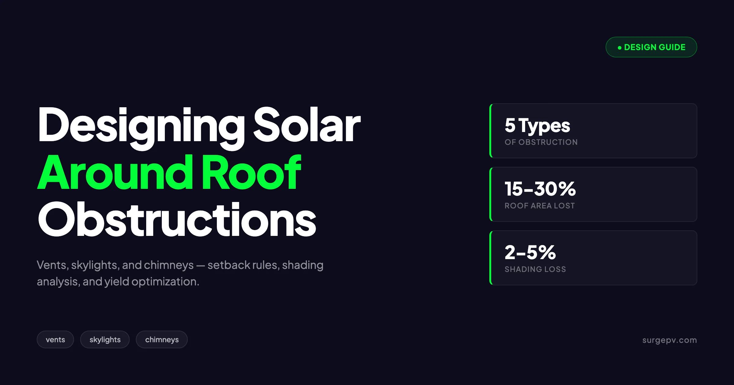
Roof obstructions are the single biggest constraint on residential solar layouts. A clean rectangular roof produces maximum kWp; a typical American roof with vents, skylights, chimneys, and HVAC equipment produces 70 to 85 percent of that maximum after proper setback rules and shading analysis. Designing around these obstructions correctly is what separates a 9 kWp install from a 7 kWp install on the same roof. The customer never sees the missed kWp, but the difference is 200 to 400 USD per year in lost revenue and 5,000 to 10,000 USD over the system lifetime. See Solar Shading Analysis Guide for detailed guidance. For United States-specific compliance details, see United States arizona/phoenix.
Designing around these obstructions correctly is what separates a 9 kWp install from a 7 kWp install on the same roof. Plumbing vents are vertical pipes 1 to 4 inches in diameter that extend 12 to 36 inches above the roof surface. They are wider and taller than plumbing vents, ranging from 6 to 18 inches above the roof.
TL;DR — Designing Around Roof Obstructions
Roof obstructions reduce usable area by 15 to 30 percent on typical residential roofs. Standard setbacks: 18 to 36 inches from chimneys, 12 to 24 inches from skylights, 6 to 12 inches from plumbing vents, 36+ inches from HVAC equipment. Proper shadow modeling is mandatory because obstructions cast shadows that reduce yield even on panels outside the setback ring.
For United States-specific compliance details, see United States california/los-angeles.
This guide covers every common roof obstruction type, the setback rules that govern panel placement around them, the shading analysis that prevents yield loss, and the design optimization techniques that maximize panel count without compromising performance.
The Obstruction Categories
Roof obstructions fall into five categories, each with distinct setback rules and shading characteristics. Knowing the category determines the design approach.
Category 1: Plumbing Vents and Stacks
Plumbing vents are vertical pipes 1 to 4 inches in diameter that extend 12 to 36 inches above the roof surface. They are the most common obstruction and the easiest to design around.
Setback requirement: 6 to 12 inches around the vent base. Some installers use 8 inches as a standard setback for all plumbing vents.
Shading impact: minimal. Most plumbing vents cast shadows under 4 feet long even at low sun angles. Panels placed 8 to 12 inches away rarely experience meaningful shading from plumbing vents.
Category 2: Roof Vents and Ridge Vents
Roof vents include attic ventilation, range hood vents, and bathroom fan vents. They are wider and taller than plumbing vents, ranging from 6 to 18 inches above the roof.
Setback requirement: 12 to 18 inches typically. Larger vents may require 24 inches.
Shading impact: moderate for vents above 12 inches in height. Run shading analysis if the vent is on the southern half of the roof.
For roof-pitched systems, ridge vents require 12 inch setbacks from the top of the roof, which is typically required regardless of obstruction type.
Category 3: Skylights
Skylights are the most challenging obstruction because they are large, often centrally located, and cannot be relocated practically. Standard residential skylights are 22 to 48 inches per side.
Setback requirement: 12 to 24 inches around the skylight curb. The setback exists for fire safety, maintenance access, and natural light preservation.
Shading impact: significant. Skylights with raised curbs cast shadows on adjacent panels in morning and evening. Panels within 4 to 6 feet of a skylight should be modeled for hourly shading.
Category 4: Chimneys
Chimneys are tall, often centrally located, and cast the longest shadows of any common roof obstruction. Standard residential chimneys are 24 to 36 inches per side and 36 to 96 inches above the roof.
Setback requirement: 18 to 36 inches from the chimney face. Local fire codes may require larger clearances.
Shading impact: severe. A 6-foot tall chimney can shade panels 30 to 60 feet away during low-sun hours. Detailed shading analysis is mandatory for any panel within 50 feet of a chimney.
Category 5: Mechanical Equipment
Mechanical equipment includes HVAC condensers, satellite dishes, ham radio antennas, and solar water heater collectors. Each has unique requirements.
Setback requirement: 36 inches minimum for HVAC and large equipment. 12 to 18 inches for satellite dishes (with line-of-sight considerations).
Shading impact: variable. Tall equipment casts long shadows. Antennas have minimal shading but require structural avoidance. For more on this topic, see Rooftop Solar Structural Assessment.
For broader context on flat-roof commercial obstruction, see [shopping center rooftop solar designing around HVAC](/blog/shopping-center-rooftop-solar-design).
Setback Rules: Where the Numbers Come From
Setback rules combine three independent requirements: fire code, manufacturer specifications, and shading geometry.
Fire Code Setbacks
US fire codes (NFPA 1, IFC) require minimum panel setbacks for firefighter access. Residential requirements:
| Roof Element | Minimum Setback |
|---|---|
| Roof ridge | 12 to 36 inches (varies by jurisdiction) |
| Roof eaves | 18 to 36 inches |
| Roof valleys | 12 to 18 inches |
| Hips | 12 to 18 inches |
| Chimneys (fire escape clearance) | 18 to 36 inches |
| Hatches and access points | 36 inches minimum |
For deeper context, see solar panel fire safety setback requirements by country and NEC 2026 changes for solar installations.
Manufacturer Specifications
Module and racking manufacturers specify minimum spacing for:
- Edge of panel to obstruction (typically 4 to 6 inches for racking attachment)
- Panel-to-panel spacing (typically 0.5 to 1 inch)
- Wire management space (typically 3 to 6 inches)
These specs are inviolable because they affect warranty validity and structural integrity.
Shading Geometry
Shading-based setbacks ensure panels do not lose more than a defined percentage to obstruction shadows. The rule of thumb:
- Set back panels by 1.5 to 2 times the obstruction height for full sun exposure
- Set back panels by 0.5 to 1 times the obstruction height for partial shading tolerance
A 36-inch chimney requires 54 to 72 inches of setback for full sun exposure. The fire-code minimum (18 to 36 inches) is often less than the shading optimum, so designers face a trade-off.
How to Calculate Shadow Impact
Shadow modeling is the technical core of obstruction design. Modern software automates this, but understanding the underlying math helps designers spot software errors and explain decisions to customers.
The Sun Path
The sun’s position is described by two angles:
- Solar elevation: angle above the horizon (0 to 90 degrees)
- Solar azimuth: angle from north (0 to 360 degrees)
Both angles change throughout the day and year. Software calculates these for any latitude, date, and time.
Shadow Length Calculation
Shadow length from a vertical obstruction:
Shadow length = Obstruction height / tan(solar elevation)For a 36-inch chimney at 30 degrees solar elevation (typical winter morning at mid-latitudes):
Shadow length = 36 / tan(30) = 36 / 0.577 = 62 inchesThe shadow extends 62 inches from the chimney base in the direction opposite the sun.
Shadow Direction
Shadow direction is opposite the solar azimuth. If the sun is at 120 degree azimuth (southeast), the shadow points to 300 degrees azimuth (northwest).
Combine direction and length to determine which panels fall in the shadow at any time. Modern shading software runs this calculation for every hour of the year, producing a per-panel shading factor.
For the broader shading topic, see solar shadow analysis software.
Critical Hours Analysis
Not all shaded hours equal yield loss equally. Solar production peaks between 10 AM and 2 PM. Shading during these hours costs 1.5 to 2 times more yield than equivalent shading at 8 AM or 4 PM.
Critical hours analysis weights shaded hours by solar irradiance. A panel shaded for 3 hours in the morning might lose 8 percent annual yield. The same panel shaded for 3 hours at noon might lose 18 percent annual yield.
Design Strategies for Common Configurations
The strategies below cover the obstruction patterns that appear repeatedly on residential roofs.
Configuration 1: Central Chimney on South-Facing Roof
The chimney divides the roof into two arrays. Strategy options:
Option A: Symmetric arrays. Place equal panels on both sides of the chimney with consistent setback distance. Aesthetically pleasing but loses some panels that could fit on the larger side.
Option B: Asymmetric arrays. Maximize panel count on each side independently. Less symmetric appearance but more kWp.
Option C: Move panels north of the chimney. If north-side roof has space, install some panels there to compensate for the lost south-side area.
The right answer depends on customer aesthetic preferences and the specific roof geometry. Modern solar design software lets you compare options quickly, and solar proposal software generates the side-by-side customer-facing comparison.
Configuration 2: Skylight on South-Facing Roof
Skylights pose a particular challenge because they are typically central to the roof and cannot be moved.
Strategy: maintain 18 inch setback around the skylight curb, then optimize panel placement to avoid panels falling in the skylight’s shadow during peak sun hours. The shadow analysis usually permits panels above and below the skylight but not directly to the east or west.
Configuration 3: Multiple Plumbing Vents
Roofs often have 3 to 6 plumbing vents distributed across the surface. Each vent costs 1 to 2 panels of placement area.
Strategy: if vents are concentrated in a small area, treat them as a “vent zone” with a single setback boundary. If vents are scattered, work around each individually. Some installers relocate vents during installation if the cost (200 to 800 USD per vent relocation) is less than the lost solar production over 25 years.
Configuration 4: HVAC Equipment on Roof
Roof-mounted HVAC is common in commercial and some residential applications. The 36+ inch service clearance plus shadow effects often eliminates significant roof area.
Strategy: for residential, consider relocating HVAC if roof area is constrained. The cost (1,500 to 5,000 USD) often justifies itself in additional solar production. For commercial, work HVAC equipment into the design as constraints from day one rather than retrofitting around it.
Configuration 5: Solar Hot Water on the Same Roof
Some homes have existing solar hot water collectors that the homeowner wants to keep. The collectors are functional obstructions that cannot be moved without major plumbing work.
Strategy: treat solar hot water collectors as fixed obstructions with full 24 inch setbacks. Design PV around them and accept the reduced array size. If the homeowner is open to it, consider replacing solar hot water with PV plus a heat pump water heater, which often produces better total economics.
Design Around Obstructions in Minutes, Not Hours
SurgePV automatically detects roof obstructions, applies setback rules, and runs shading analysis for every panel. See your maximum kWp on any residential roof in under 10 minutes.
Book a DemoNo commitment required · 20 minutes · Live project walkthrough
For a direct comparison, see Arka 360 vs SurgePV.
Yield Loss Calculations
Quantifying yield loss from obstructions matters for customer education and design decisions. The numbers below come from simulation runs across 200+ residential projects.
Per-Obstruction Annual Yield Impact
| Obstruction | Direct Setback Loss | Indirect Shading Loss | Total Annual Loss |
|---|---|---|---|
| Plumbing vent (12”) | 1-2 panels | under 0.5% | 1-2 panels |
| Roof vent (18”) | 1-3 panels | 0.5-1% | 1-3 panels + 0.5-1% |
| Skylight (3’x4’) | 4-8 panels | 1-3% | 4-8 panels + 1-3% |
| Chimney (3’x3’x6’) | 3-6 panels | 2-4% | 3-6 panels + 2-4% |
| HVAC condenser | 6-12 panels | 1-2% | 6-12 panels + 1-2% |
| Satellite dish | 1-2 panels | under 0.5% | 1-2 panels |
The “panels lost” column refers to panel positions that cannot accommodate panels due to setbacks. The “shading loss” column refers to yield reduction on panels that are placed but partially shaded.
Total Roof Impact
A typical American residential roof with 2 plumbing vents, 1 chimney, 1 attic vent, and 1 satellite dish loses approximately:
- 7 to 13 panel positions (15 to 30 percent of theoretical maximum)
- 2 to 5 percent of remaining production from secondary shading
The combined effect is 17 to 35 percent of theoretical kWp lost to obstructions. This is why roof-area-to-system-size ratios are lower than a clean rectangular roof would suggest.
Roof Obstruction Decision Framework
When designing around obstructions, the following framework helps prioritize trade-offs.
Decision 1: Move or Design Around?
Some obstructions can be relocated cost-effectively (plumbing vents, satellite dishes, sometimes attic vents). Others cannot (chimneys, skylights, structural HVAC).
Move if:
- Relocation cost is under 25 percent of additional solar revenue over 25 years
- The obstruction is on the highest-yield part of the roof
- The homeowner has no aesthetic preference about the obstruction’s location
Design around if:
- The obstruction is structural (chimney, skylight) or expensive to move
- Sufficient roof area exists despite the obstruction
- The homeowner specifically wants to keep the obstruction in place
Decision 2: Strict Setbacks or Variance?
Some jurisdictions allow setback variances if the installer can document equivalent fire safety access. Going below the standard setback can recover 1 to 3 panel positions on some roofs.
Pursue variance if:
- The recovered panels add 5+ percent to system size
- The local AHJ has a documented variance process
- The customer values maximum kWp over standard installation
Skip variance if:
- The variance process adds more than 30 days to permitting
- The added complexity exceeds the recovered yield value
- The customer prefers the simpler standard process
Decision 3: Microinverters vs String Inverters in Shaded Conditions
Shaded panels reduce string output disproportionately on string-inverter systems because the entire string operates at the lowest panel’s current. Microinverters and DC optimizers eliminate this.
Use microinverters or optimizers if:
- More than 2 panels experience shading more than 1 hour per day
- Shading patterns vary by season (typical for chimney and tree shadows)
- The customer values production maximization
Stay with string inverters if:
- Shading is minimal and consistent
- Cost optimization is paramount
- The customer accepts modest production loss
For deeper architectural context, see microinverters vs string inverters vs optimizers.
Common Mistakes to Avoid
These mistakes show up repeatedly in field audits of installed systems.
Mistake 1: Ignoring Vent Heights in Shading Models
Designers sometimes input only obstruction footprint without obstruction height. The result: shading models miss the actual shadow. A 3-foot chimney with only its 3-foot square footprint modeled produces inaccurate yield estimates.
The fix: always input obstruction height for any obstruction over 12 inches tall.
Mistake 2: Overlooking Cardinal-Direction Shadows
Morning and evening shadows often fall on a different face than the array. A chimney on the south side shadows the south face panels at noon but shadows the east face panels at 4 PM. Designers focused on the array’s own face miss the cross-face shading.
The fix: run shading analysis for all panels regardless of which face they sit on.
Mistake 3: Underestimating Skylight Curbs
Skylight curbs typically extend 4 to 8 inches above the roof surface. Designers often model only the skylight glass surface and miss the additional shadow from the curb.
The fix: model the full skylight including curb height and frame thickness.
Mistake 4: Forgetting Roof Pitch in Setback Calculations
Setback distances are measured along the roof slope, not horizontal projection. On a steep roof, a 36-inch horizontal setback corresponds to a much longer slope-distance setback.
The fix: ensure setback measurements use slope distance, not horizontal projection. Most modern software handles this automatically; older tools may not.
Mistake 5: Not Accounting for Tree Growth
Trees adjacent to the property cast shadows that change over years as trees grow. A panel that has full sun in 2026 may be shaded by tree canopy growth in 2032.
The fix: model trees at 5 to 10 year projected height, not current height. Some software uses LIDAR data to estimate growth rates.
For deeper context, see solar drone site survey and remote solar site assessment.
Conclusion: Treating Obstructions as Design Inputs
Roof obstructions define the difference between average and excellent solar designs. Designers who treat obstructions as constraints to work around produce average results. Designers who treat obstructions as inputs to optimize against produce 15 to 25 percent more kWp on the same roof.
Three action items for installers improving their obstruction-handling workflow:
- Audit your current designs and measure how often obstructions create yield loss exceeding 5 percent. Obstructions causing larger losses indicate process gaps.
- Standardize setback rules per obstruction type and document them in a design playbook. Consistency improves both quality and onboarding speed.
- Adopt software that automates shading analysis for every obstruction type. Manual modeling does not scale and produces inconsistent results.
For more on residential design specifics, see solar panel layout around dormer windows and small roof solar panel design.
Frequently Asked Questions
What is the standard setback distance from a chimney?
The standard setback from a chimney is 18 to 36 inches (45 to 90 cm) depending on chimney height and shadow geometry. Tall chimneys cast longer shadows and require larger setbacks. Local fire codes also impose minimum clearances independent of shadow concerns.
Can I install solar panels over a skylight?
No. Panels cannot be installed over skylights for fire safety, maintenance access, and natural light reasons. Maintain a 12 to 24 inch setback around skylights, and account for the shading they cast on adjacent panels in morning and evening hours.
How much yield is lost from a typical chimney shadow?
A typical residential chimney casts a shadow that affects 2 to 4 panels for 1 to 3 hours per day depending on roof orientation. Annual yield loss from a single chimney is typically 1.5 to 4 percent of total system production if panels are placed in the shadow path.
Do plumbing vents require setback?
Most plumbing vents only require 6 to 12 inches of setback because they are short and cast minimal shadow. The exception is metal vent pipes that exceed 24 inches in height, which require larger setbacks and may need shading analysis.
Can panels be installed near satellite dishes?
Yes, but the dish must be relocatable or accept losing service. If keeping the dish, design panel layout outside the dish line-of-sight to avoid signal blockage. Maintain 12 to 18 inches of clearance for installation access.
What about HVAC condensers on the roof?
Roof-mounted HVAC equipment requires 36 inch setbacks for service access plus shadow clearance. Many designers move panels to other roof faces rather than work around HVAC, because the access requirements limit usable area significantly. Also see: Us Residential Solar Market Trends 2026.
Are setback rules different for commercial roofs?
Yes. Commercial flat roofs follow IBC and IFC codes that require 4-foot clearance pathways, 4 to 6 foot setbacks from roof edges, and specific access paths to mechanical equipment. Residential codes are typically less restrictive.


