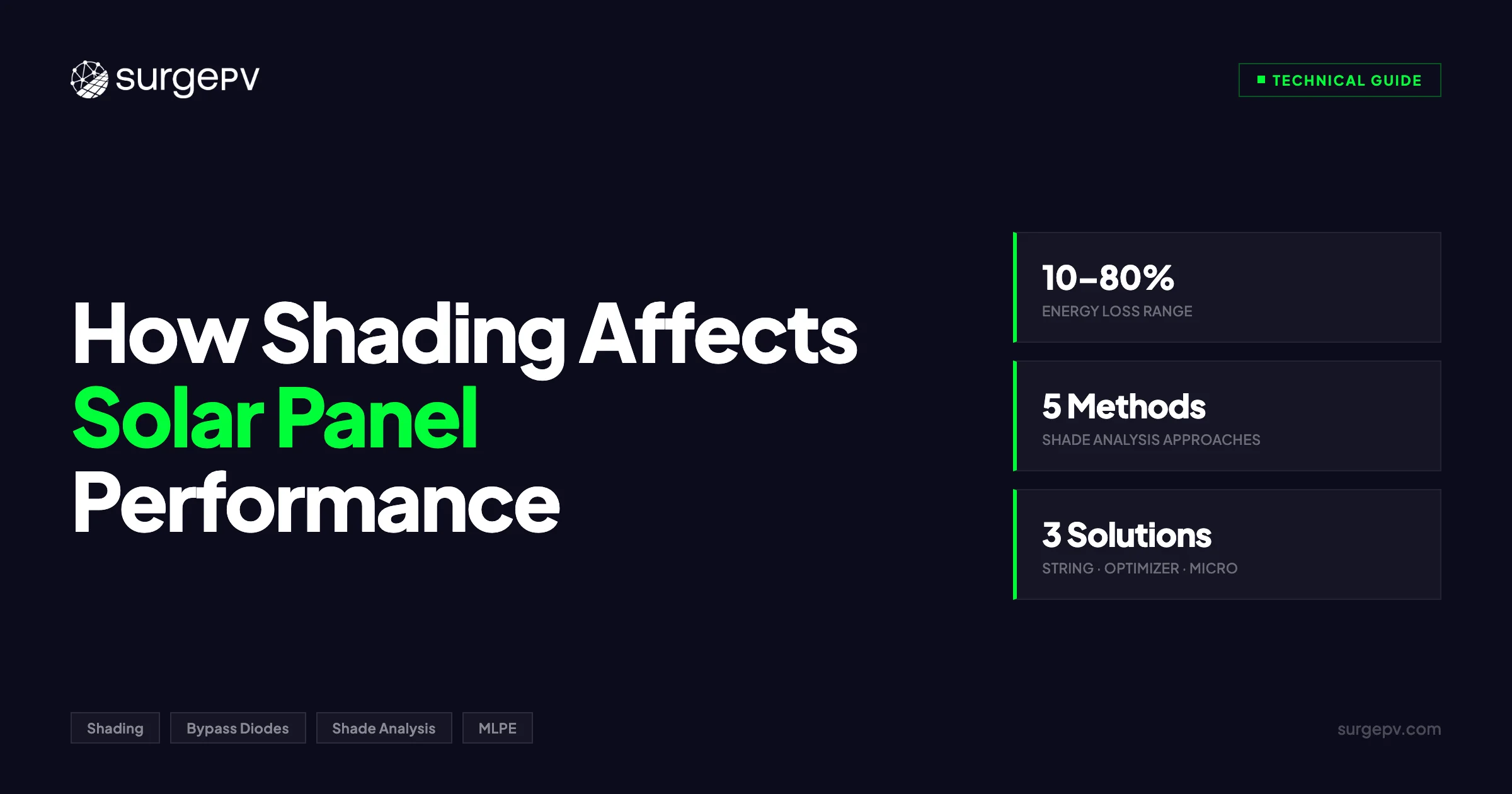
Quick Answer
Shading on solar panels causes disproportionate energy losses due to series string effects. A single shaded panel can reduce a string's output by 30–50%. Solutions include DC optimizers, microinverters, and strategic panel placement.
Shade a single cell on a 400 W solar panel and you can lose 150 W of output. That is not a typo. A cell that represents 1.5% of the panel’s surface area can wipe out 35-40% of total power.
Shading on solar panels causes disproportionate energy losses due to series string effects. A single shaded panel can reduce a string’s output by 30–50%. Solutions include DC optimizers, microinverters, and strategic panel placement. For more on this topic, see [Solar Shading Analysis Guide](/blog/solar-shading-analysis-guide).
Solar cells connected in series act like a chain, and the weakest link sets the pace. Understanding how shading destroys output, and what you can do about it in system design, separates a profitable installation from an underperforming one.
This guide covers shade loss physics, shading types and severity, bypass diodes and modern cell designs, real energy loss data by inverter topology, professional shade analysis methods, and design strategies that minimize shade impact.
TL;DR
Shading 10% of a panel’s surface can cause 30-40% power loss in string inverter systems. Bypass diodes limit damage but do not eliminate it. Half-cut cell panels, microinverters, and DC optimizers each recover significant energy in shaded conditions. Professional 3D shade analysis before installation prevents the worst losses and pays for itself many times over.
What this guide covers:
- Why partial shading causes disproportionate energy loss at the cell level
- Types of shading ranked by severity and frequency
- How bypass diodes, half-cut cells, and shingled cells mitigate shade
- Real energy loss data: string inverters vs. optimizers vs. microinverters
- Five shade analysis methods compared by accuracy and cost
- Design strategies to minimize shade impact on any roof
- How SurgePV’s 3D shadow simulation quantifies shade losses
Why Even Partial Shading Destroys Solar Output
To understand shade losses, you need to understand how solar cells are connected inside a panel.
A standard 60-cell or 120-half-cut-cell panel wires its cells in series. Current flows through every cell sequentially, and the cell producing the least current limits the entire string. Same principle as a garden hose: pinch it at one point and water flow drops everywhere downstream.
The Cascade Effect
When sunlight hits a solar cell, it generates both voltage and current. A fully illuminated monocrystalline PERC cell produces roughly 10-11 A of short-circuit current (Isc). Shade that cell by 50%, and its Isc drops to approximately 5 A.
Here is where the damage multiplies. Every other cell in the string is still trying to push 10 A, but the shaded cell can only pass 5 A. The entire string current drops to 5 A. If 20 cells are in that series group, you lose roughly half the output of all 20 cells because of shade on one.
A fully shaded cell produces almost no current. The other cells try to force current through it, and the shaded cell becomes a resistive load. It absorbs power instead of generating it, converting that energy into heat. This is how hot spots form, and why bypass diodes exist.
The 10% Shade, 40% Loss Rule
Industry field data consistently shows that shading 10% of a panel’s surface can reduce output by 30-40% in a string inverter system. This is not a worst-case scenario. It is the expected outcome whenever shade falls across cells in a series group.
Key Takeaway
Solar cells in series behave like links in a chain. One weak cell drags down every cell in its group. A 10% shaded area does not produce a 10% loss. It produces a 30-40% loss because the shaded cell limits the current for every cell connected to it in series.
A study by Sandia National Laboratories found that a single fully shaded cell in a 60-cell module reduced module power by 33% when one bypass diode activated, and by 66% when two bypass diode groups were affected.
Shade matters far more than its physical footprint suggests. A chimney shadow that covers three cells at 2 PM every day can cost 5-8% of annual system production, depending on string layout and inverter type. That is hundreds of dollars in lost revenue per year over a 25-year system life.
Types of Shading and Their Severity
Not all shade is equal. A nearby building casting a permanent shadow has a different financial impact than bird droppings on a single cell. Understanding the types helps you prioritize analysis effort and design mitigation.
Shading Types Ranked by Impact
| Shading Type | Examples | Duration | Typical Annual Loss | Severity |
|---|---|---|---|---|
| Permanent structural | Adjacent buildings, walls, parapets | Year-round, predictable hours | 10-30% | High |
| Seasonal vegetation | Deciduous trees (leafy in summer) | 4-6 months, variable | 5-20% | High |
| Evergreen vegetation | Pine trees, hedges | Year-round | 8-25% | High |
| Self-shading (row spacing) | Front row shading back row on flat roofs | Winter months, low sun angles | 3-8% | Medium |
| Temporary objects | Antennas, poles, wires | Fixed but small shadow | 1-5% | Medium |
| Soiling and debris | Dust, pollen, bird droppings, leaves | Variable, accumulates over time | 2-7% | Medium |
| Snow cover | Snow accumulation on panels | Days to weeks, seasonal | 1-10% (climate-dependent) | Low-High |
| Cloud shading | Passing clouds | Minutes to hours | 0-3% (uniform, not series-limited) | Low |
Permanent structural shading is the most damaging because it is predictable, consistent, and often covers a large area. A two-story building 5 meters south of a single-story roof can shade the entire array during winter afternoons. If this is not caught during the design phase, no amount of equipment upgrades will fully recover the lost energy.
Self-shading from row-to-row spacing on flat roofs and ground mounts is common and preventable. Designers who cut row spacing to fit more panels often create a net negative: the extra panels produce less total energy than fewer panels with proper spacing. For more on this topic, see Ground Mounted Solar Design Guide.
Soiling is the most overlooked category. A 2023 study in Solar Energy found that uneven soiling creates partial shading conditions similar to physical objects, with measured losses of 3-7% annually in dusty or high-pollen environments. Regular cleaning recovers most of this, but many system owners skip maintenance entirely.
Pro Tip
During site assessment, photograph the roof at the time of maximum shading (typically December 21 at solar noon for Northern Hemisphere sites). This captures the worst-case shadow lengths. If the site passes the winter solstice test, it will perform well year-round.
How Bypass Diodes and Panel Design Mitigate Shade
Panel manufacturers have built shade mitigation directly into module design. Every modern panel includes bypass diodes, and newer cell architectures further limit damage.
Bypass Diodes
A bypass diode is a semiconductor switch wired in parallel with a group of cells. In a standard 60-cell panel, three bypass diodes divide the panel into three groups of 20 cells. When one cell in a group is shaded, the bypass diode activates and routes the string current around the entire 20-cell group.
What bypass diodes do: Prevent hot spots by giving current an alternative path. They also keep the rest of the string running.
What bypass diodes do not do: Recover the lost power from the shaded group. When a bypass diode activates, you lose approximately one-third of the panel’s output (for a 3-diode panel). The shaded group contributes zero power.
Half-Cut Cell Panels
Half-cut cell technology cuts each standard cell in half, doubling the cell count from 60 to 120 (or 72 to 144). The top half and bottom half operate as two independent circuits that combine in parallel at a junction box.
Three benefits for shade tolerance:
-
More bypass diode groups. A 120-half-cut-cell panel typically has 6 bypass diode groups (3 per half) instead of 3. Each group has fewer cells, so less output is lost when one group is bypassed.
-
Half-panel independence. If shade covers only the bottom row, the top half continues at full output. In a full-cell panel, the same shade would activate bypass diodes across the entire module.
-
Lower current, lower resistive losses. Half-cut cells carry half the current of full cells, which reduces I²R losses and hot spot temperatures.
For a detailed comparison of half-cut vs. full-cell panel performance, see our guide on half-cut vs full-cell solar panels. See our guide on Agricultural Solar Case Study for more.
Shingled Cell Panels
Shingled cell technology overlaps cells like roof shingles, eliminating gaps between cells and creating more parallel paths for current flow. Each “strip” of shingled cells operates semi-independently.
Shingled panels can lose one strip to shade while the remaining strips continue producing. In field tests, shingled panels showed 5-15% better energy yield than standard full-cell panels under partial shade.
Shade Mitigation by Panel Technology
| Technology | Bypass Diode Groups | Shade Isolation | Relative Shade Tolerance |
|---|---|---|---|
| Standard 60-cell | 3 (20 cells each) | One-third panel per group | Baseline |
| Half-cut 120-cell | 6 (20 cells each, 2 independent halves) | One-sixth panel per group | 15-25% better |
| Shingled | 5-6 parallel strips | Per-strip isolation | 20-30% better |
| IBC (back-contact) | 3-4 groups | Varies by manufacturer | 10-20% better |
Quantifying Shade Losses: Real Data
Actual energy loss from shading depends on three variables: how much of the array is shaded, the panel technology, and the inverter topology.
How Inverter Topology Affects Shade Loss
String inverters connect panels in series. One MPPT tracker manages the entire string. When one panel is shaded, the string current drops and the inverter operates at the reduced current for every panel.
DC power optimizers (SolarEdge, Tigo) sit behind each panel and perform per-module MPPT. The optimizer adjusts each panel’s voltage to maintain maximum current. Shade on one panel does not reduce current through other panels.
Microinverters (Enphase, APsystems) convert DC to AC at each panel. Each panel is electrically independent. Shade on one panel has zero impact on any other.
Energy Loss Comparison by Scenario
| Shade Scenario | String Inverter Loss | Optimizer Loss | Microinverter Loss |
|---|---|---|---|
| 1 cell shaded (50%) on 1 panel in 10-panel string | 25-35% of string | 15-20% of 1 panel | 15-20% of 1 panel |
| 1 panel fully shaded in 10-panel string | 50-80% of string | 90-100% of 1 panel | 90-100% of 1 panel |
| 2 panels partially shaded (25% each) in 10-panel string | 30-50% of string | 10-15% of 2 panels | 10-15% of 2 panels |
| Morning shadow on 3 panels (2 hours/day) | 8-15% annual string loss | 3-5% annual system loss | 2-4% annual system loss |
| Chimney shadow on 1 panel (4 hours/day, winter) | 5-10% annual string loss | 1-3% annual system loss | 1-3% annual system loss |
The pattern is consistent: string inverters amplify shade losses across the string, while module-level power electronics (MLPE) contain losses to the affected panels.
Key Takeaway
In a string inverter system, one shaded panel in a 10-panel string can reduce string output by 50-80%. With optimizers or microinverters, the same shade scenario loses only the output of the one affected panel. On roofs with known shade issues, MLPE can recover 20-30% of annual production compared to string inverters.
The Financial Impact
Consider a 10 kWp residential system producing 14,000 kWh/year. At an electricity rate of €0.30/kWh, that is €4,200 in annual value.
| Shade Level | String Inverter Annual Loss | MLPE Annual Loss | 25-Year Difference |
|---|---|---|---|
| Light (5% annual) | €315/year | €126/year | €4,725 |
| Moderate (10% annual) | €630/year | €252/year | €9,450 |
| Heavy (20% annual) | €1,260/year | €504/year | €18,900 |
The cost premium for microinverters or optimizers on a 10 kWp system is typically €500-€1,500. On any roof with moderate shading, MLPE pays for itself within the first two years. Accurate shade analysis before installation directly determines the financial return of the system.
For detailed ROI calculations and financial modeling, SurgePV’s generation and financial tool quantifies shade-adjusted energy production and payback periods automatically. For a direct comparison, see Arka 360 vs SurgePV.
See How Shade Affects Your Next Project
SurgePV’s 3D shadow simulation shows hour-by-hour shade patterns and quantifies energy losses before you install a single panel.
Book a DemoNo commitment required · 20 minutes · Live project walkthrough
Shade Analysis Methods
Identifying and quantifying shade before installation prevents the losses described above. Five methods are used in the industry, from simple field tools to advanced 3D simulation.
Method 1: Sun Path Diagrams
A sun path diagram plots the sun’s position (azimuth and elevation) across every hour of every month. By standing at the panel location and noting which obstructions intersect the sun paths, you can estimate which hours will be shaded.
Accuracy: Low to moderate. Depends heavily on the operator’s skill. Does not account for diffuse irradiance loss.
Best for: Quick field screening. Ruling out obviously poor sites.
Method 2: Solar Pathfinder
The Solar Pathfinder is a dome-shaped reflective device placed at the panel location. It reflects the surrounding skyline onto a sun path chart, showing shaded hours visually.
Accuracy: Moderate. Better than manual sun path estimation. Limited to the single point where the device is placed.
Best for: Residential site visits where a quick shade assessment is needed. Popular in the US market.
Method 3: Fisheye Lens Photography
A camera with a 180-degree fisheye lens captures the full hemisphere above the panel location. Software then overlays sun paths onto the image to calculate annual shading hours.
Accuracy: Moderate to good. Captures the full horizon in a single photo. Software analysis adds consistency.
Best for: Detailed site documentation. Creates a permanent record of the shade environment.
Method 4: 3D Software Simulation
Modern solar design software builds a 3D model of the site including buildings, trees, and terrain. The software runs automated shading analysis, simulating shadow patterns for every hour of the year (8,760 hours) using the actual sun position for the site’s coordinates.
Accuracy: High. Under 3% annual prediction error with accurate 3D models. Validated against metered production data across thousands of installations. Also see: Us Residential Solar Market Trends 2026. For United States-specific compliance details, see United States arizona/phoenix. For United States-specific compliance details, see United States california/los-angeles.
Best for: Any project where accuracy matters. Residential, commercial, and utility-scale. This is the industry standard for bankable shade analysis.
Method 5: LiDAR and Drone Photogrammetry
LiDAR scans create centimeter-accurate 3D point clouds of a site. Drone photogrammetry uses overlapping aerial photos to build 3D models. Both feed into simulation software for shade analysis.
Accuracy: Very high. Sub-centimeter 3D accuracy. Best combined with software simulation.
Best for: Large commercial rooftops, ground-mount projects, and sites with complex obstructions.
Shade Analysis Methods Compared
| Method | Accuracy (Annual) | Time per Site | Cost | Equipment Needed |
|---|---|---|---|---|
| Sun path diagram | ±15-25% | 30-60 min | Free | Printed chart |
| Solar Pathfinder | ±10-15% | 15-30 min | $300-$400 (device) | Pathfinder device |
| Fisheye lens photo | ±8-12% | 15-30 min | $200-$500 (lens + software) | Camera + fisheye lens |
| 3D software simulation | ±2-3% | 10-30 min | Software subscription | Computer + solar design software |
| LiDAR/drone survey | ±1-2% | 1-4 hours | $500-$2,000/site | Drone or LiDAR scanner |
The gap between manual methods (±15-25% accuracy) and 3D simulation (±2-3%) is significant. On a system producing 15,000 kWh/year, a 15% prediction error means your estimate could be off by 2,250 kWh — €675/year in misestimated value. Over 25 years, the cumulative impact runs into tens of thousands.
For a full comparison of shading analysis platforms, see our guide on solar shading analysis tools. Read more about Floating Solar Farms France.
Free Tool
Try our shading analysis tool to estimate shade losses for your next project based on obstruction height, distance, and panel orientation.
Design Strategies to Minimize Shade Impact
Once shade analysis identifies the problem areas, the system design should respond. Six strategies, applied in combination, minimize shade impact on any roof.
Strategy 1: Panel Placement
Do not put panels where shade falls. Many designers pack panels into every available square meter without checking shade patterns beyond a single snapshot.
Map shade across all 12 months. A spot that is shade-free in June may be fully shaded in December. Remove panels from locations that receive more than 2 hours of daily shade during the primary production season (March through October in the Northern Hemisphere).
Strategy 2: String Routing
How you wire panels into strings determines how shade on one panel affects others. The goal: keep shaded and unshaded panels on separate strings.
Rules for shade-aware string design:
- Group panels by shade exposure. Panels that get morning shade should be on the same string, separate from panels that are shade-free all day.
- Run strings vertically on the roof (portrait orientation) when shade moves horizontally across the array.
- Never mix panels from different roof faces on the same string if one face has shade and the other does not.
For more on string design principles, see common solar string design mistakes that reduce system performance.
Strategy 3: Equipment Selection
The inverter topology decision follows directly from the shade analysis.
Decision tree:
- No shade (under 5% annual loss): String inverter is fine. Lowest cost, highest efficiency.
- Light shade (5-10% annual loss): DC optimizers offer the best cost-to-recovery ratio.
- Moderate to heavy shade (over 10% annual loss): Microinverters or optimizers. The extra cost is recovered within 1-3 years.
- Complex shade patterns (multiple obstructions, varying heights): Microinverters. Per-panel independence handles unpredictable shade patterns best.
Strategy 4: Panel Technology Selection
On roofs with known shade issues, specify half-cut cell or shingled cell panels. The per-panel shade tolerance improvement of 15-30% compounds across the array.
Half-cut cell panels are now the industry default. The cost premium over full-cell panels has disappeared in many markets. Read our comparison of half-cut vs full-cell solar panels for the full analysis. For France-specific information, see France Solar Feed-in Tariffs.
Strategy 5: Row Spacing on Flat Roofs
Self-shading from front rows onto back rows is the most preventable shade loss. The minimum row spacing depends on latitude and tilt angle.
Rule of thumb: At 30-35 degrees latitude, use a row spacing of at least 1.5 times the panel height (measured from the rear edge to the ground). At 45-50 degrees latitude, increase to 2.0 times the panel height to account for lower winter sun angles.
Cutting row spacing to fit more panels often backfires. A 20-panel array with proper spacing may produce more annual energy than a 24-panel array with self-shading during winter months.
Strategy 6: Vegetation Management
Trees are the most common shade source for residential rooftops. If the homeowner agrees, trimming or removing trees can recover more energy than any equipment upgrade.
Show the homeowner the specific annual kWh loss caused by the tree using simulation data. A $500 tree trimming that recovers $400/year in production is an easy sell.
Pro Tip
When designing for a roof with partial shade, run two simulations: one with string inverters and one with microinverters. Show the customer the kWh difference and the cost difference. Let the data make the equipment decision. This approach builds trust and closes deals faster than any sales pitch. Use SurgePV’s solar proposal software to present both scenarios side by side.
Shade Analysis with SurgePV
SurgePV’s shadow analysis tool integrates shade identification, quantification, and design optimization into a single workflow.
3D Shadow Simulation
The platform builds a 3D model of the site using satellite imagery and LiDAR data. You can add buildings, trees, chimneys, and other obstructions manually or import them from aerial surveys. The simulation engine calculates shadow patterns for every hour of the year based on the site’s exact coordinates.
The output is a visual shadow map overlaid on the roof surface, showing which panels are shaded at which times. Annual shade loss for each panel position is calculated individually.
Impact Quantification
SurgePV calculates the energy impact in kWh and financial impact in your local currency. The generation and financial tool factors in the specific inverter topology (string, optimizer, or microinverter) to show shade losses under each equipment scenario.
You can show the customer exactly how much energy they will lose to shade with each design option, and what the financial difference is over 25 years. The solar proposal software presents this data in a customer-ready format.
Design Optimization
After identifying shade zones, SurgePV’s solar design platform lets you adjust panel placement, string routing, and equipment selection in real time. Move a panel and the energy estimate updates instantly. Switch from string inverter to microinverter and the shade-adjusted production recalculates.
This iterative workflow is why 3D software simulation has replaced manual shade assessment for professional installers.
Frequently Asked Questions
How much does shade reduce solar panel output?
Shade impact ranges widely depending on the shading pattern, panel technology, and inverter type. A single shaded cell in a string inverter system can reduce output by 30-40%. A fully shaded panel in a 10-panel string can cut string output by 50-80%. With microinverters or DC optimizers, losses are limited to the affected panel only, typically 15-20% per shaded module.
Do solar panels still work in partial shade?
Yes, solar panels still generate electricity in partial shade, but at reduced output. Bypass diodes route current around shaded cell groups, so the unshaded portions continue producing. Half-cut cell panels handle partial shade better than full-cell designs because they have more bypass diode segments. Microinverters or optimizers further limit shade losses to only the affected panels.
What is the best inverter for shaded roofs?
Microinverters or DC power optimizers are the best choice for shaded roofs. Both isolate each panel electrically so that shade on one module does not drag down the others. Microinverters from Enphase or APsystems convert DC to AC at each panel. Optimizers from SolarEdge or Tigo pair with a central inverter. Either approach recovers 20-30% of the energy that a string inverter would lose in partially shaded conditions.
How do you do a shade analysis for solar panels?
Professional shade analysis uses one of four methods: sun path diagrams with a Solar Pathfinder device, fisheye lens horizon photography, 3D software simulation using LiDAR or drone data, or satellite-based remote analysis. 3D simulation in tools like SurgePV is the most accurate method, achieving under 3% annual prediction error by modeling hour-by-hour shadow patterns across all 8,760 hours of the year.
Do half-cut cell panels handle shade better than standard panels?
Yes. Half-cut cell panels split each panel into two independent halves, each with its own set of bypass diodes. When shade covers only the top or bottom half, the unshaded half continues at full output. In a standard full-cell panel, the same shade pattern would activate bypass diodes across the entire panel. Field tests show half-cut panels recover 5-10% more energy than full-cell panels in partial shade conditions. See our full comparison of half-cut vs full-cell solar panels.
Further Reading
Explore our complete shading analysis guide for a deep dive into shade modeling methods, software comparison, and design strategies for every roof type.


