A professional solar installation follows 10 defined steps - and the sequence matters. Skip a step or do them out of order and you risk equipment damage, a failed inspection, or a callback. This chapter covers each step with specific technical requirements, torque specs, and the IEC 62446 commissioning tests required before customer handover.
What you'll learn
- Required PPE and tools before work begins
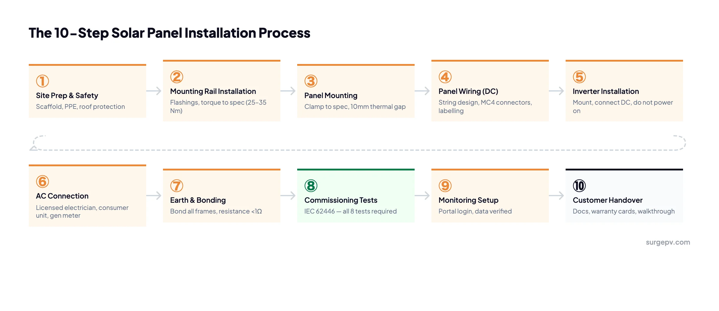
- Steps 1–5: site prep, mounting rails, panel placement, DC wiring, inverter install
- Steps 6–7: AC connection and earthing requirements
- Steps 8–9: IEC 62446 commissioning tests - all 8 required
- Step 10: documentation and customer handover checklist
- The 5 most common installation mistakes and how to avoid them
Before You Start: Tools, Safety & Pre-Installation Checks
Solar panels produce voltage the moment they see light. Cover them with opaque sheeting before you start any DC wiring work - do not rely on overcast weather as a safeguard.
Required PPE
- Hard hat on all roof work
- Safety harness attached to a certified anchor point
- Insulated gloves (rated for at least 1000V) for DC electrical work
- Safety glasses during drilling and cable work
- Non-slip footwear on roof surfaces
Required Tools
- Torque wrench - set to manufacturer spec. Rail bolts: typically 25–35 Nm. Module clamps: typically 14–20 Nm. Never guess torque.
- Cable crimping tool - for MC4 connector assembly
- Multimeter - for polarity and voltage checks throughout
- Insulation resistance tester - minimum 500V DC test voltage, required for IEC 62446
- DC clamp meter - for Isc measurement during commissioning
- Spirit level - for rail alignment
Pre-Installation Design Check
Before arriving on site, confirm the string design matches the inverter's MPPT input window. A string that exceeds the inverter's maximum DC input voltage will void the warranty and can cause permanent damage. Good solar design software generates string voltage calculations automatically - verify them before ordering equipment.
Pro Tip
Print the as-built drawings and the commissioning test sheet before you leave the office. You'll need both on site, and a missing document at handover is a common reason jobs don't get signed off on the first visit.
Steps 1–3: Site Prep, Mounting Rails, Panel Placement
Step 1: Site Prep & Roof Protection
Set up scaffold or roof edge protection before anyone goes on the roof. Lay scaffold boards or rubber protection mats to distribute load and protect tiles. Mark all roof penetration points on the drawing before drilling - a misplaced hole is hard to fix and creates a leak point.
- Apply butyl tape to flashing brackets at every penetration point
- Check structural members with a rafter finder before placing any fixing
- Confirm roof load capacity if the system is over 20 kWp - especially on older buildings
Step 2: Mounting Rail Installation
Install roof hooks or ground screws through the flashings. Torque all fixings to the manufacturer's specified value - this is not advisory. Under-torqued fixings fail in wind; over-torqued fixings crack tiles.
- Roof hook torque: manufacturer spec, typically 25–35 Nm depending on hook design
- Level rails using a spirit level - check horizontally and along the rail length
- Rail spacing: follow panel manufacturer spec, typically at 1/3 and 2/3 of panel length from the bottom edge
- Leave a rail expansion gap of approximately 5mm at each splice joint
Step 3: Panel Mounting
Place panels starting from the middle of the array and working outward. This ensures the final panels on each end are symmetrical and that any minor rail alignment errors don't accumulate at one side.
- Module clamp torque: check the datasheet - typically 14–20 Nm for mid-clamps and end-clamps
- Leave a 10mm gap between adjacent panels for thermal expansion
- Never stand on the panels - the glass and cell structure cannot support a person's weight
- Keep panels covered with opaque sheeting during Step 3 - they are generating voltage
Key Point
Wrong torque on module clamps is the number one cause of wind damage callbacks. An overtightened clamp cracks the aluminium frame; an undertightened clamp allows the panel to shift. Torque every clamp - do not estimate.
Steps 4–5: DC Wiring & Inverter Installation
Step 4: Panel Wiring (DC)
String design should be finalised in your solar design software before installation. On site, your job is to wire to that design exactly.
- Cable cross-section: typically 4mm² for short strings, 6mm² for longer strings - follow the design specification
- MC4 connectors must be fully clicked home - you should hear a distinct click and feel the lock engage. A partial connection creates a hot spot that will eventually arc.
- Label each string at both ends: string number, polarity (+/−), and panel count
- Route cables in conduit or cable management tray where exposed to UV - unprotected cable UV-degrades within a few years
- Keep DC cables as short as possible - excess length adds resistance and reduces yield
After wiring all strings, confirm polarity with a multimeter before connecting to the inverter. A reversed string damages the inverter's MPPT input - some inverters have reverse polarity protection, many do not.
Step 5: Inverter Installation
Mount the inverter in a shaded, well-ventilated location. String inverters on the interior wall just below the roof entry point is the most common placement for residential systems - it minimises DC cable length.
- Follow the manufacturer's minimum clearance requirements - inverters overheat if mounted too close to walls or other equipment
- Connect the DC string cables to the inverter inputs but do not switch the inverter on at this stage
- If the inverter has a DC isolator, leave it in the off position
- Install all required labels: DC isolator, AC isolator, "Solar PV system - isolate before working on mains supply"
Steps 6–7: AC Connection & Earthing
Step 6: AC Connection
In most EU countries, all AC electrical work on a solar installation must be carried out by a qualified electrician. Check your national requirements before starting - attempting AC work without the required certification risks voiding your insurance and failing inspection.
- Connect the inverter AC output cable to a dedicated circuit breaker in the consumer unit or distribution board
- The breaker rating should match the inverter's maximum AC output current - check the datasheet
- Install a generation meter between the inverter and the connection point if required by your grid operator or feed-in tariff program
- In three-phase installations, confirm phase balance - an unbalanced connection reduces performance and may trip protection relays
Regulatory Note
In the UK, all AC solar PV work falls under Part P of the Building Regulations and must be carried out by a Part P registered electrician or notified to Building Control. In Germany, AC connection work requires a registered electrician (Elektrofachkraft). Verify the requirement for your country before starting.
Step 7: Earth & Bonding
Earthing (equipotential bonding) connects all metal parts of the solar array to the main earth of the building. This is not optional - an unbonded array is a shock hazard and will fail inspection.
- Bond all module frames to each other via the mounting rail system, then bond the rail system to the main earth conductor
- Target resistance: below 1Ω between any module frame and the main earth bar - you'll verify this with the continuity test in Step 8
- Install a ground fault protection relay if required by local code (standard in most EU countries)
- Use green/yellow earth cable throughout - do not use any other colour for earth conductors
Steps 8–9: IEC 62446 Commissioning & Monitoring Setup
Step 8: IEC 62446 Commissioning Tests
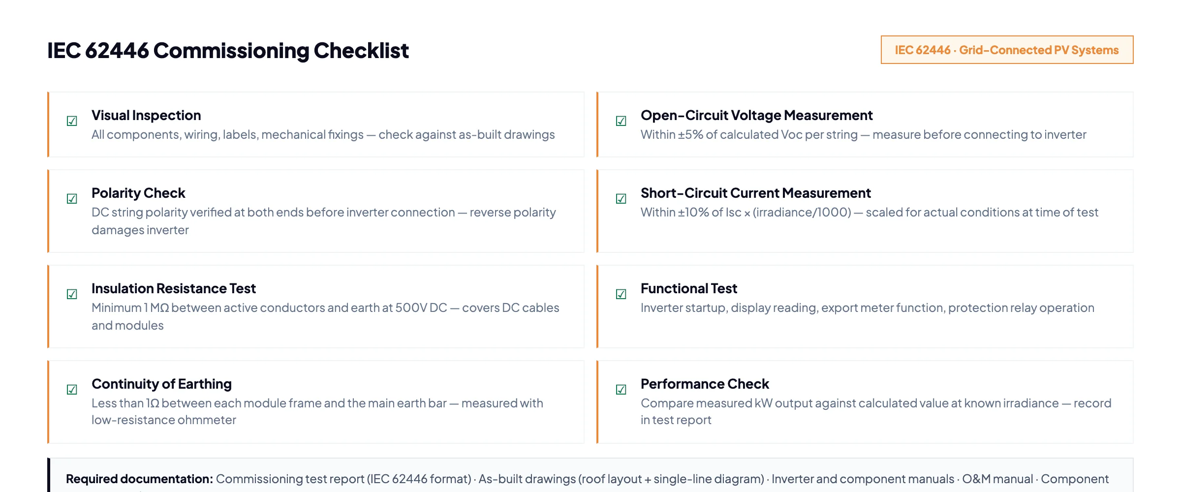
This is the most important phase. Do not skip any test, and do not energise the system before all tests pass. IEC 62446 defines 8 required tests for grid-connected PV systems.
Work through each test in sequence. If any test fails, stop, diagnose, and fix the fault before continuing. Record every test result in the commissioning report.
- Visual inspection - check all components against the as-built drawings. All wiring tidy, all labels present, all fixings torqued, no damaged panels or cables.
- Polarity check - confirm DC polarity at every string termination using a multimeter. Do this before connecting strings to the inverter.
- Insulation resistance test - apply 500V DC between active conductors and earth. Minimum pass threshold is 1 MΩ. A lower reading indicates damaged cable insulation or a wiring fault.
- Continuity of earthing - measure resistance between each module frame and the main earth bar. Must be below 1Ω.
- Open-circuit voltage (Voc) measurement - measure string Voc and compare against the calculated value. Should be within ±5%. A significantly low reading indicates a failed panel or poor connection.
- Short-circuit current (Isc) measurement - measure string Isc and compare against the expected value scaled for actual irradiance: Isc × (measured irradiance / 1000). Should be within ±10%.
- Functional test - energise the inverter. Confirm the display shows correct readings, that the export meter operates in the correct direction, and that protection relay function works as specified.
- Performance check - compare the measured AC output (kW) against the calculated output for the actual irradiance at the time of the test. Record both values in the test report.
Step 9: Monitoring Setup
After all tests pass and the system is energised:
- Create the monitoring platform account using the customer's email address - not yours
- Pair the inverter to the monitoring gateway and verify data is flowing on the portal
- Confirm the export meter reading appears correctly (where applicable)
- Set the customer's alert thresholds - typically an alert if daily generation drops below 20% of expected yield
Pro Tip
Take a screenshot of the monitoring portal showing real-time generation before you leave site. Include it in the handover pack - customers appreciate seeing the system working on day one.
Step 10: Customer Handover & Documentation
A professional handover takes 20–30 minutes and leaves the customer confident they know how their system works. Rushing this step is a mistake - a well-informed customer generates fewer support calls and is far more likely to refer you.
Required Documentation
You must provide all of the following at handover:
- Commissioning test report - IEC 62446 format, signed and dated. This is the legal record of system compliance.
- As-built drawings - roof layout showing panel positions, strings, and cable routes; single-line electrical diagram showing inverter, isolators, meters, and consumer unit connection.
- System manual - includes inverter datasheet, panel datasheet, mounting system datasheet, and warranty documents for each component.
- Component warranty cards - panels (typically 10–12 years product warranty, 25–30 years performance warranty), inverter (typically 5–10 years), and racking system.
- Monitoring platform credentials - login details, app instructions, and who to contact if the system shows an error.
- Grid operator confirmation - copy of the DNO notification or connection approval letter.
Handover Walkthrough
Walk the customer through three things in person:
- How to read the inverter display or monitoring app - what the numbers mean and what a normal day's generation looks like
- Where the DC isolator and AC isolator are, and when to use them (in a fault condition or emergency)
- What to do if they see an error - who to call, what information to have ready
Design Solar Installations Faster with SurgePV
Generate string voltage calculations, as-built drawings, and customer proposals in one platform.
Book Free Demo20 minutes · Live walkthrough · No commitment
The 5 Most Common Installation Mistakes
These errors come up repeatedly in site audits and insurance claims. Every one of them is preventable.
1. Wrong Torque on Module Clamps
Overtightening cracks the aluminium frame and voids the panel warranty. Undertightening allows panels to shift in wind, which eventually causes connector strain, cable damage, and in rare cases, panel loss from a roof. Use a torque wrench on every clamp - no exceptions.
2. Incorrect String Voltage
Stringing more panels in series than the inverter's maximum input voltage allows will destroy the inverter's MPPT stage - usually within the first hot day of operation, when cold-start Voc is at its peak. Calculate string voltage at -10°C (or the local design minimum temperature) before finalising string design. Solar design software does this automatically; spreadsheets often get it wrong.
3. Skipping the Insulation Resistance Test
A wiring fault that passes visual inspection will show up on an insulation resistance test. Faults left undetected can cause DC arc faults - a leading cause of solar-related fires. The IR test costs five minutes; a DC arc fault costs everything.
4. Unprotected Cable Routing
DC cables left exposed to UV without conduit or cable clips will degrade within 3–5 years. The insulation cracks, creating an arc or shock hazard. All exposed cable runs must be in UV-stabilised conduit or secured in cable management tray.
5. Missing Earthing Bonds
An unbonded module frame sits at an indeterminate voltage relative to earth - it can give a dangerous shock on contact. Missing earth bonds also fail inspection and require a return visit. Run the continuity test on every frame before completing commissioning.
Frequently Asked Questions
How long does it take to install solar panels?
Residential systems (5–10 kWp): 1–2 days for a two-person team, including scaffolding setup and commissioning. Commercial systems (50–200 kWp): 1–3 weeks depending on roof complexity, access equipment, and grid connection requirements.
Do you need an electrician to install solar?
Yes, in most EU countries. The AC connection must be carried out by a qualified electrician. In some countries - including the UK (MCS certification), Germany (Elektrofachkraft), and France (Qualifelec) - the installer must hold a specific accreditation to carry out the full installation or to access grid incentives.
What is IEC 62446?
IEC 62446 is the international standard for commissioning and testing grid-connected photovoltaic systems. It defines the minimum set of tests and documentation required before a system is handed over to the customer. The 8 required tests cover visual inspection, polarity, insulation resistance, earth continuity, open-circuit voltage, short-circuit current, functional testing, and performance verification.
About the Contributors

CEO & Co-Founder · SurgePV
Keyur Rakholiya is CEO & Co-Founder of SurgePV and Founder of Heaven Green Energy Limited, where he has delivered over 1 GW of solar projects across commercial, utility, and rooftop sectors in India. With 10+ years in the solar industry, he has managed 800+ project deliveries, evaluated 20+ solar design platforms firsthand, and led engineering teams of 50+ people.