Quick Answer
Solar panel installation follows six steps: site assessment and shading analysis, system design and permitting, equipment procurement, mounting structure installation, DC/AC wiring and inverter connection, and grid inspection with net metering activation. Residential projects take 1–3 days for installation; permitting adds 2–8 weeks.
A solar panel installation is only as good as its weakest step. Panels can be premium monocrystalline TOPCon, the inverter can be a Tier 1 brand with ten-year warranty, and the mounting rails can be certified for 180 km/h wind — and none of that matters if the DC strings are wired in the wrong polarity, the roof penetrations are not waterproofed correctly, or the earthing system doesn’t comply with the local grid code. Read Solar Racking Design Guide for a complete walkthrough.
Solar panel installation follows six steps: site assessment and shading analysis, system design and permitting, equipment procurement, mounting structure installation, DC/AC wiring and inverter connection, and grid inspection with net metering activation. Residential projects take 1–3 days for installation; permitting adds 2–8 weeks.
For more details, see our guide on PERC vs TOPCon vs HJT field performance.
For more details, see our guide on solar panel warranty comparison. For France-specific information, see Agricultural Solar Case Study.
For more details, see our guide on NEC 2026 solar changes.
For more details, see our guide on solar cable sizing calculation.
For more details, see our guide on TOPCon vs HJT vs perovskite solar panels.
For more details, see our guide on floating solar design.
Solar panel installation follows six steps: site assessment and shading analysis, system design and permitting, equipment procurement, mounting structure installation, DC/AC wiring and inverter connection, and grid inspection with net metering activation. Residential projects take 1–3 days for installation; permitting adds 2–8 weeks.
For more details, see our guide on drone inspection for solar farms.
For more details, see our guide on solar panel temperature coefficient.
For more details, see our guide on solar shading analysis guide.
For more details, see our guide on how shading affects solar panels.
Installation quality determines system performance over a 25-year asset life. A poorly executed installation can cost a customer 15–20% annual yield loss from shading that was never modeled, arc faults from undersized cable, or inverter shutdowns from ground fault conditions that were never detected during commissioning. These losses compound across decades and generate warranty claims, call-backs, and reputational damage that no sales margin can absorb.
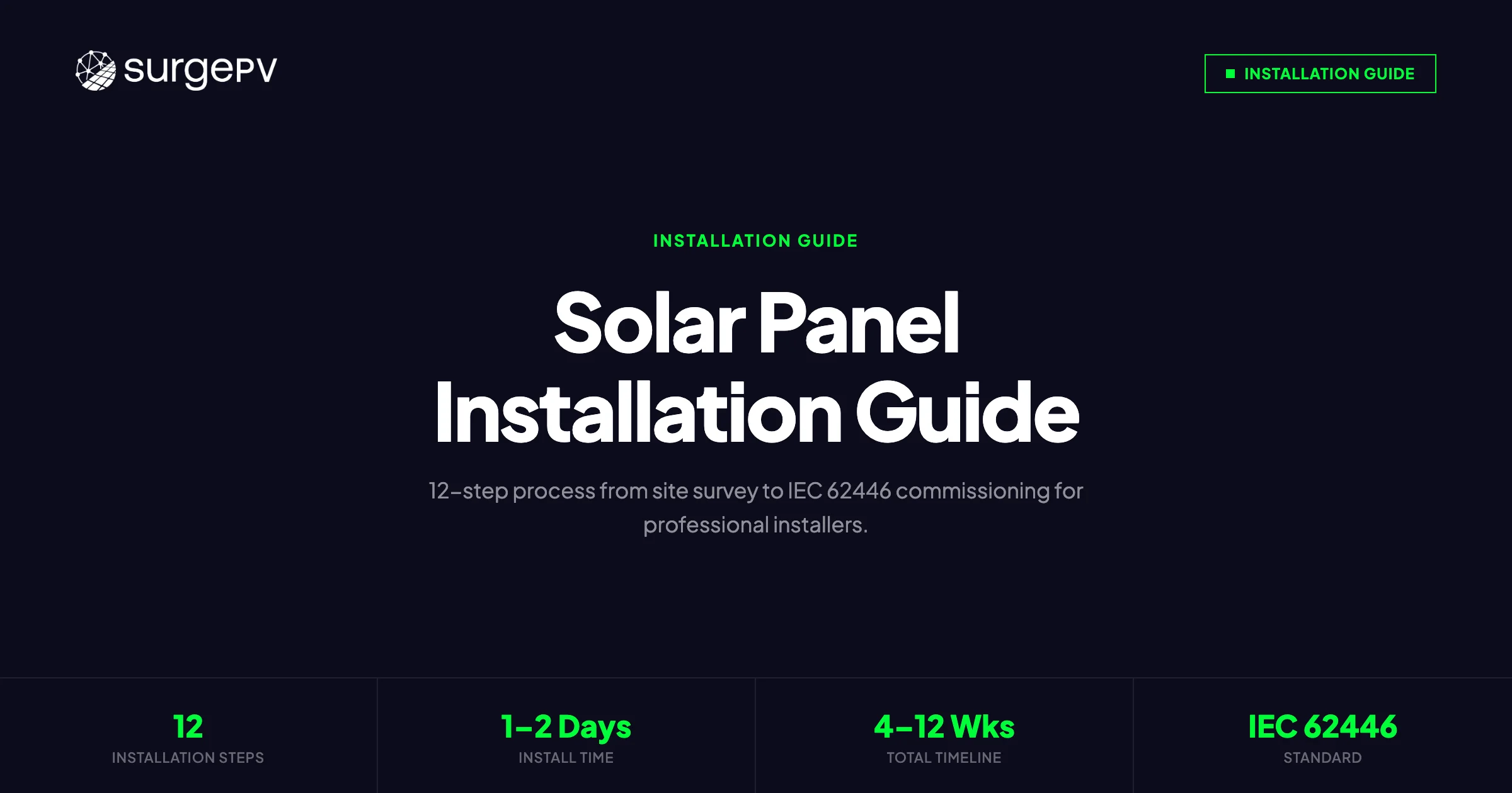
This guide covers the complete installation process in 12 sequential steps — from design verification (using solar proposal software output as the source of truth) and site survey through IEC 62446 commissioning tests to customer handover documentation. It is written for professional installers working on residential and light commercial systems (3–200 kWp), with specific references to European and NEC 690 requirements where they diverge. Also see: European Solar Incentives. For Europe-specific compliance details, see Europe solar compliance.
TL;DR — Solar Panel Installation Guide 2026
Professional solar installation requires 12 sequential steps: site survey, permitting, structural assessment, mounting, panel fixing (torque to spec), DC wiring, inverter commissioning, AC connection, earthing, IEC 62446 tests (IV curve, insulation resistance, continuity), monitoring setup, and handover documentation. Skipping or rushing any phase increases the risk of inspection failure, yield loss, or long-term safety incidents. Use design-phase output — shading model, string layout, single-line diagram — as the installation reference from day one.
In this guide:
- Latest 2026 updates to solar installation standards
- Step 1: Design verification and pre-installation site survey
- Step 2: Permitting, grid application, and documentation preparation
- Step 3: Structural assessment and roof preparation
- Step 4: Mounting system installation — racking, rails, flashings
- Step 5: Panel placement and mechanical fixing (torque specs, clearance requirements)
- Step 6: DC wiring — string cables, combiner boxes, conduit routing
- Step 7: Inverter installation and commissioning
- Step 8: AC connection and meter installation
- Step 9: Earthing and bonding
- Step 10: IEC 62446 commissioning tests — IV curve, insulation resistance, continuity
- Step 11: Monitoring system setup and data verification
- Step 12: Handover documentation and customer training
- Common installation mistakes — and how design software prevents them
For more details, see our guide on rooftop solar structural assessment.
For more details, see our guide on how to become a solar designer.
For more details, see our guide on solar PV design software. Read Advanced Solar PV Design Software for a complete walkthrough.
Latest Updates: Solar Installation Standards 2026
Several important standard updates affect installations commissioned from mid-2025 onward. Installers working across EU markets need to be aware of the following changes before picking up a drill.
IEC 62446-1:2016+AMD1:2023 — The amendment introduced updated requirements for IV curve tracing during commissioning, with explicit tolerances for string voltage and current deviation. Deviations greater than 3% in Isc or 2% in Voc from the STC-corrected expected values must now be documented and investigated, not simply noted. Many inspection authorities in Germany, the Netherlands, and France are enforcing the amendment requirements on new installations from January 2026. Also see: Germany solar subsidies. Also see: France solar feed-in tariffs.
EN 50618:2014 reviewed — The European standard for electric cables for photovoltaic systems is under revision as of 2025. Current installations must continue using cables meeting EN 50618 or equivalent (UL 4703 in the US market), but installers should verify cable certification before procurement as some distributor stock dates from before the 2023 RoHS compliance update.
For more details, see our guide on how solar panels work.
NEC 2023 Article 690 — Rapid Shutdown Zone expansion. In the United States, the 2023 NEC adoption cycle is active in an increasing number of states. Rapid shutdown requirements now extend to all roof-mounted systems regardless of string count, with module-level power electronics (MLPE) or rapid shutdown devices required within 30 cm of each module.
For more details, see our guide on microinverters vs string inverters vs optimizers.
IEC 61730 Edition 2 — Module safety qualification standard was updated to include more rigorous hot-spot endurance and mechanical load tests. Modules certified only to Edition 1 may face issues with some structural engineers’ sign-off requirements for high-wind or high-snow load regions.
Grid connection timing — Several EU DSOs (Distribution System Operators) have extended grid connection processing times in high-penetration areas (parts of southern Germany, the Veneto and Emilia-Romagna regions of Italy, and Andalucía in Spain). Build a minimum 8-week buffer from grid application to expected commissioning date in these regions. Also see: solar panel ROI in Italy. Also see: Spain net metering.
Step 1: Design Verification and Pre-Installation Site Survey
The design file — produced in solar design software during the sales or proposal phase — is the starting point for the physical installation. Before any material is ordered or delivered to site, verify that the design matches reality.
For more details, see our guide on best solar design software guide.
What the Design Verification Covers
Pull up the design output and cross-reference it against the actual site conditions:
- Roof dimensions and orientation. Satellite imagery has a margin of error of ±15 cm on older datasets. For pitched roofs, measure actual ridge-to-eave distance and verify against the design. A 30 cm error on a 12-row layout can mean one fewer row of panels — that is a material change in yield.
- Shading model accuracy. The design’s shading simulation should match the field view. Walk the roof or use a Solmetric SunEye or equivalent shading analysis device at the proposed module positions. Mature trees, new dormer construction, and neighboring building extensions are common sources of design-versus-field mismatch. Use solar shadow analysis software in the design phase to generate time-stamped shading reports; on site, validate them with physical measurement.
- String layout and MPPT assignment. Confirm that the proposed string configurations are achievable with the physical module positions. Verify that no string crosses roof planes, which would violate the design’s shading assumptions.
- Roof access and safety routes. OSHA 1926.502 (US) and EN 13374 (EU) require identified safe access routes, emergency egress, and anchor points. Confirm that the anchor positions indicated in the design are compatible with actual roof structure.
Pre-Installation Checklist
Work through the following before signing off for material delivery:
- Roof covering condition assessed — no broken tiles, no delamination on membrane roofs
- Roof pitch and orientation measured and confirmed against design (±5° tolerance)
- Structural load-bearing capacity verified or structural engineer report obtained
- Shading analysis validated with on-site measurement
- Obstructions mapped: HVAC units, skylights, vents, chimneys with required clearances marked
- Roof dimensions measured and panel layout confirmed with physical tape measure
- Conduit routing planned from array to inverter — wall penetrations and conduit path confirmed
- Inverter location confirmed: shaded, ventilated, within allowable cable run distance
- Grid connection point identified: main panel, sub-panel, or dedicated connection
- Emergency access and fall protection anchor points identified
Pro Tip — Site Survey Photo Documentation
Photograph every key element during the site survey: roof condition, shading sources, proposed module positions, conduit route, switchboard, and meter location. Timestamp-enabled photos create a permanent record that protects you in warranty disputes and accelerates inspector sign-off. Store these in the project folder alongside the design output from your solar design software.
Design Discrepancies — When to Re-Design
If the site survey reveals a significant discrepancy from the design — more than one row of panels lost, a shading source that invalidates the string layout, or a structural issue requiring a different mounting system — stop and revise the design before ordering materials. Continuing with a known discrepancy and “adjusting on the fly” during installation is the single largest driver of commissioning failures and post-installation performance complaints.
Use your solar software to run the revised layout before material procurement. A 30-minute redesign saves a 3-hour site visit and a truck roll for missed materials.
Step 2: Permitting and Grid Application
Permitting requirements vary significantly by jurisdiction, but the principles are consistent: notify the relevant authorities before work begins, submit accurate technical documentation, and do not energize the system until approval is received.
Building Permits
In the EU: Most residential PV installations fall under simplified notification procedures (comunicazione preventiva in Italy, Errichtungsanzeige in Germany, declaration préalable in France) rather than full building permits, provided the installation does not alter the building’s roof profile beyond defined thresholds. Check local planning authority requirements — some municipalities with conservation area designations require full planning consent. For Italy-specific information, see Commercial Rooftop Solar Case Study Italy.
In the US: Nearly all residential and commercial PV installations require an electrical permit and, where applicable, a structural permit. Submit the permit application with the single-line diagram (SLD), roof plan with module layout, equipment data sheets (panels, inverter, rapid shutdown devices), and structural calculations if required by the AHJ.
Grid Connection Application
Submit the grid application to the DSO (Distribution System Operator) or utility as early as possible — ideally within 48 hours of signed contract. In many EU markets, the DSO has a legal obligation to respond within defined timeframes (8 weeks in Germany under EnWG, 60 days in Italy under ARERA Resolution 770/2019) but processing times often exceed these limits in high-penetration areas.
For more details, see our guide on solar PPA pricing models.
The grid application typically requires:
- Site address and grid connection point identifier (meter number / POD code)
- Proposed inverter make, model, and rated AC power output
- Connection diagram showing the AC connection point
- Load assessment for net metering (self-consumption calculation)
- Anti-islanding declaration confirming inverter grid protection compliance (VDE-AR-N 4105 for Germany, CEI 0-21 for Italy, G98/G99 for the UK)
Documentation to Prepare Before the Installation Date
Gather the following and have them on site during installation:
- Approved permit (or permit application reference number)
- Grid application acknowledgment from DSO
- Equipment data sheets and installation manuals for panels, inverter, and mounting system
- Single-line diagram (finalized from design phase)
- Material delivery manifest for cross-reference on arrival
Step 3: Structural Assessment and Roof Preparation
Roof structure failure is rare but catastrophic when it occurs. Installers carry liability for structural assessment — a signed-off job with inadequate structural analysis creates long-term exposure.
Structural Assessment Requirements
For residential timber-framed or truss roofs (most common in the UK, Northern Europe, and North America): For UK-specific information, see Battery Solar System Design UK.
- Rafter spacing and size: Standard rafter spacing of 400–600 mm with 47×150 mm or larger cross-section is adequate for most residential PV loads in wind zones up to 150 km/h, provided mounting loads are distributed across a minimum of 3 rafters per array edge.
- Dead load addition: A standard crystalline silicon panel array adds 12–18 kg/m² dead load including panels, racking, and fixings. Verify the existing roof dead load plus the PV addition does not exceed the structural limit. In the UK, BS 6399-1 provides the live and dead load reference values.
- Snow load regions: In Alpine Europe, Scandinavia, and high-altitude US installations, verify snow load accumulation under and behind the array does not create uplift or concentrated point loads exceeding rafter design limits.
For flat-membrane roofs (common in commercial installations):
- Penetration-free ballasted systems require structural confirmation that the ballast load (typically 25–40 kg/m²) is within the roof’s structural capacity. This often requires a structural engineer’s stamp.
- Confirm membrane age and condition. Installations on membranes less than 5 years from end of warranty period create liability issues — flag this to the customer before proceeding.
Roof Preparation
Before racking goes on:
- Clear the roof of debris — moss, lichen, and loose material must be removed. Do not use pressure washing on clay tile roofs.
- Replace damaged tiles or flashing in the installation zone. Reusing cracked tiles under rail mounts creates future leak paths.
- Mark rafter positions using a stud finder from inside the attic space and transfer the marks to the tile/cladding surface using chalk line.
- Install additional waterproofing at all penetration points before rafter bolts or direct-penetration anchors are installed.
Step 4: Mounting System Installation
The mounting system is the mechanical foundation of the array. Errors here — misaligned rails, undertorqued fasteners, incompatible materials — result in structural failure, water ingress, or voided panel warranties.
Racking System Selection
Match the racking system to the roof type:
| Roof Type | Recommended Mount Type | Notes |
|---|---|---|
| Clay/concrete tile | Tile hook with flashing | Hook must match tile profile; universal hooks acceptable for shallow pitch |
| Metal standing seam | Seam clamp (no penetration) | Zero-penetration attachment; use seam clamp rated for seam profile width |
| Corrugated metal | L-foot with EPDM washer | Penetration required; seal with self-healing EPDM flashing |
| Asphalt shingle | Flashed lag bolt to rafter | Torque to 20–25 Nm; seal with butyl tape and flashing |
| Flat membrane (ballasted) | Ballasted tray system | Confirm roof capacity; anti-wind retention blocks at perimeter |
| Flat roof (penetration) | L-foot through membrane | Use industry-standard flashing kit rated for roof system |
Rail Installation
- Set the bottom rail position based on the panel layout dimensions from the design. Leave minimum 200 mm clearance from the roof edge (EU standard) or as defined by the AHJ.
- Install roof anchors at every rafter, or per manufacturer specification for the specific roof type. For lag bolt anchors into rafters, use 10 mm diameter stainless steel lag bolts (A4-316 grade for coastal environments) minimum 50 mm embedment into rafter.
- Attach mid-rail support brackets per manufacturer rail span limits. Do not exceed rated span — this is the most common racking field error.
- Install rails and set level. Use a spirit level and laser level for arrays longer than 4 rails. Rail misalignment greater than 3 mm over 3 meters will cause module frame binding and stress fractures at panel clamps.
- Set rail end caps and install grounding lugs at rail splice joints where the racking system relies on rail conductivity for equipment bonding.
For more details, see our guide on solar energy myths debunked.
Key Takeaway — Racking Material Compatibility
Use stainless steel (A4-316 grade) fasteners on aluminum rails universally. Galvanized steel fasteners in contact with aluminum rails cause galvanic corrosion within 5–7 years in coastal or high-humidity environments. The cost difference between A4 and galvanized fasteners on a residential system is typically under €40 — the warranty claim and call-back cost is not.
Step 5: Panel Placement and Mechanical Fixing
Panel handling and mechanical fixing is where physical damage to modules most often occurs. A cell crack from improper handling will not be visible to the naked eye on the day of installation, but will show up as a permanent hotspot and yield degradation within 6–12 months.
Panel Handling Protocols
- Never carry a panel by its junction box or cable leads. Hold at the frame corners.
- Do not stand or kneel on panels. Despite marketing claims about hail resistance, the mechanical load of a human adult kneeling on the center of a 2.1m panel will crack cells.
- Transport panels vertically or in the provided packaging, never flat-stacked in unbraced piles on the roof.
- Inspect each panel before fixing. Run a visual check for shipping damage: frame deformation, glass cracks (front and rear), junction box detachment, and cable insulation damage.
Placement Sequence
Start from the bottom of each row and work upward. Install bottom clamps first, slide the panel into position, and install upper clamps before moving to the next panel. This prevents the lower-mounted panels from sliding before upper clamps are set.
For portrait orientation arrays, install one column at a time from left to right (or right to left, consistently). Do not mix portrait and landscape in a single string unless the shading model explicitly accounts for the different cell orientation relative to shading patterns.
Torque Specifications
Over-torquing clamps is as damaging as under-torquing. Crushed panel frames crack at the clamp contact point and create stress concentration sites. Under-torqued clamps allow panel movement that fatigues cable connections and MC4 connectors.
Reference values for standard module clamps (verify against your specific racking manufacturer’s documentation):
| Fastener Type | Typical Torque (Nm) | Notes |
|---|---|---|
| Mid-clamp M8 bolt | 14–18 Nm | Per most major racking manufacturers |
| End-clamp M8 bolt | 14–18 Nm | Same specification |
| Roof anchor lag bolt (10mm, into rafter) | 20–25 Nm | After pilot hole; stop at thread engagement, do not strip |
| Rail splice bolt M8 | 10–12 Nm | Electrical continuity maintained at splice |
| MC4 connector (hand torque) | Hand-tight + quarter turn | Do not use pliers; MC4 spec is finger-tight to mechanical click |
Use a calibrated torque wrench for all structural fasteners. Write the torque setting on the installation record. Inspectors in Germany (VdS-accredited inspections) and the Netherlands (KEMA certified inspections) increasingly require torque records as part of sign-off documentation.
Module Clearance Requirements
- Bottom array clearance: 200 mm minimum from roof edge (EU) to reduce uplift forces and allow snow/debris shedding.
- Inter-row spacing: Calculated from the shading model to avoid self-shading at the design sun angle. Do not reduce inter-row spacing below the design value without re-running the shading simulation. See the solar design principles for installers guide for detailed spacing calculation methodology.
- Ventilation gap (pitched roofs): Maintain minimum 50 mm clearance between panel rear surface and roof cladding for airflow. Elevated module temperature reduces output by approximately 0.4–0.5%/°C above STC (25°C).
- Fire clearance (US installations): NEC 2023 requires a 457 mm (18-inch) setback from ridge and 457 mm from hip and valley lines on residential roofs. Some AHJs enforce additional setbacks — confirm before finalizing layout.
Step 6: DC Wiring — String Cables, Combiner Boxes, and Conduit
DC wiring errors are the leading cause of both immediate commissioning failures and long-term system degradation. Polarity reversal, undersized cable, and poorly sealed MC4 connections are responsible for a significant share of inverter warranty claims.
Cable Sizing
DC string cable must be sized for:
- Current carrying capacity — minimum rated for 1.25× the module’s Isc at STC.
- Voltage drop — target less than 1% voltage drop from furthest module to inverter. Calculate: V_drop = 2 × L × I × R/A, where L = cable length (m), I = string current (A), R = conductor resistivity (0.0175 Ω·mm²/m for copper), A = cross-section (mm²).
- Temperature derating — in conduit exposed to direct sun, derate cable ampacity per the applicable table (NEC 310.15 for US, IEC 60364-5-52 for EU). A common error: 6 mm² cable in direct-sun conduit in southern Europe may need derating to 8 mm² or 10 mm² depending on conduit fill and ambient temperature.
Standard residential string cable cross-sections:
- 4 mm² — adequate for string runs under 10 m at typical residential string currents (10–12 A)
- 6 mm² — recommended for string runs of 10–25 m; required for strings with Isc > 12 A
- 10 mm² — for runs over 25 m, or where conduit fill derating applies
All DC cable must meet EN 50618 (EU) or UL 4703 (US) for outdoor solar installation. Do not use standard building wire (NYM, THWN) for DC string runs — UV and double insulation requirements differ.
MC4 Connector Installation
MC4 connectors are the most common point of DC wiring failure in field systems. The top three errors:
- Mixing brands. MC4-compatible connectors from different manufacturers may appear to mate but do not meet the IP68 sealing or contact resistance specifications. Use the same brand throughout the array, or use connectors explicitly certified as cross-compatible by the manufacturer.
- Incomplete insertion. The contact must click into the lock position. An incompletely inserted MC4 creates a resistive joint that heats under load — a primary arc fault ignition source. Verify every connection with a firm tug after assembly.
- Damaged conductor insulation at crimp. Strip insulation to exactly the length specified by the manufacturer (typically 7–8 mm). Over-stripping leaves bare conductor exposed at the connector entry; under-stripping prevents full crimp engagement.
Pro Tip — DC String Polarity Check Before Connecting to Inverter
Before connecting any string to the inverter, use a multimeter (1,000 V DC rated minimum) to verify polarity on every string. Mark positive leads with red tape and negative with black. A reversed string will not immediately damage a modern string inverter with reverse polarity protection, but it will generate a fault code and trip the MPPT — meaning the system appears to commission correctly but one string produces zero output. Polarity checks at commissioning catch this before the customer notices months later.
Conduit Routing and Protection
- Use UV-stabilized conduit (LSZH or HDPE) for any outdoor conduit run. PVC conduit degrades within 5–7 years under direct UV exposure in southern climates.
- Route DC conduit separately from AC conduit where possible. Where they must share a trunking, ensure physical separation (metal divider) to prevent inductive coupling and simplify future fault tracing.
- Minimum bending radius for DC cable is typically 6× cable outer diameter. Tight bends at conduit entries crack insulation.
- Label DC conduit at entry and exit points with “DC SOLAR — DO NOT OPEN UNDER LOAD” or equivalent per local code.
- Seal conduit entries into the building fabric with intumescent putty to prevent fire spread and pest ingress.
For a detailed breakdown of string configuration errors and how to avoid them, see the solar string design mistakes guide.
Combiner Boxes (for commercial systems)
Systems with multiple strings feeding a single inverter input typically use a DC combiner box (string combiner) to aggregate strings before the inverter. Install combiner boxes:
- In a weather-protected location (IP65 minimum), not in direct sun if temperature derating is a concern
- With string fuse protection where required by the inverter manufacturer (typically when more than 2 strings are in parallel)
- With a DC disconnect switch rated for the full array voltage and combined short-circuit current
- Labeled with string numbers, module count, and rated Voc at STC
For more details, see our guide on [solar energy forecasting software](/blog/solar-energy-forecasting-software).
Step 7: Inverter Installation and Commissioning
The inverter is the most serviceable component in the system and the primary diagnostic interface. Poor inverter installation — wrong location, inadequate ventilation, loose DC connections at the inverter terminals — is a leading cause of premature inverter failure.
Inverter Location Requirements
- Shade from direct sun. Inverter MPPT efficiency drops and thermal protection activates when inverter ambient temperature exceeds the rated range (typically 45–60°C). A wall-mounted inverter on a south-facing exterior wall in southern Europe will routinely exceed this range on summer afternoons.
- Ventilated space. Allow minimum clearances per the manufacturer’s installation manual — typically 200 mm above and below for string inverters. Never install inside a sealed enclosure without active ventilation.
- Within allowable DC cable run. Most residential string inverters specify a maximum DC cable resistance that limits the practical string run length. Confirm cable cross-section achieves voltage drop less than 1% for the run.
- Accessible for service. Inverters require display reading, firmware updates, and occasional component replacement. Do not mount behind electrical panels, in confined crawl spaces, or above head height without a platform.
DC Termination at the Inverter
Before connecting strings at the inverter:
- Verify all strings are open-circuit (no parallel connections active).
- Measure string Voc with a calibrated meter. Compare against the expected Voc at the measured module temperature (Voc increases at lower temperatures — be careful in cold weather; a 12-panel string at −10°C can produce a Voc 15–20% above STC value, which may approach or exceed the inverter’s rated maximum input voltage).
- Check polarity on each string pair before insertion.
- Torque DC terminals to the inverter manufacturer’s specification (typically 2–3.5 Nm for M5/M6 terminal screws). Loose terminals at the inverter DC input are a top cause of arc faults.
Inverter Commissioning Steps
- Connect DC strings (inverter in standby, AC not yet connected).
- Verify DC string voltages at the inverter display or commissioning app.
- Connect AC output to the isolation switch (AC not yet live).
- Apply AC supply from the main panel.
- Follow the inverter’s commissioning wizard — set country code (this configures grid protection thresholds automatically for most modern inverters), set time and date, configure monitoring output.
- Verify the inverter detects the grid frequency and voltage within allowable range.
- Confirm the inverter starts MPPT operation and ramps to expected output.
Step 8: AC Connection and Meter Installation
The AC connection is the point where the solar system becomes part of the customer’s electrical installation — and the point where electrical safety risk is highest.
AC Protection Requirements
- Dedicated AC circuit breaker for the solar inverter output, sized per the inverter’s rated AC output current plus 25% margin.
- RCD (RCCB) protection on the inverter AC circuit is required in most EU markets. In Germany (VDE 0100-712), a Type B RCD is required at the inverter AC output to detect DC residual current components from transformer-less inverters. In the UK (BS 7671 Amendment 3), Type A or Type F RCDs are acceptable for inverters with transformer isolation or internal DC component filtering.
- AC disconnect (isolation switch) readily accessible for emergency disconnection and maintenance. Must be lockable in the open position.
- Surge protection device (SPD) at the AC connection point — required by some DSOs and strongly recommended for all systems. Type 2 SPD minimum; Type 1+2 combined for systems with exposed DC cable runs longer than 10 m.
Net Meter / Smart Meter Installation
In most markets, the DSO or utility installs the bi-directional smart meter as part of the grid connection process. The installer’s responsibility is:
- Confirming the existing meter is bi-directional (can record both import and export) — if not, notify the DSO and allow time for meter replacement before commissioning.
- Installing a generation meter on the inverter AC output circuit if required by the net metering program or the customer’s monitoring requirement (some feed-in tariff programs require a certified generation meter separate from the DSO import/export meter).
- Confirming meter wiring polarity — a reverse-connected meter records export as import and will result in incorrect billing from the first billing cycle.
Step 9: Earthing and Bonding
Earthing and bonding errors are the most common reason for inspection failure on residential and commercial PV systems. They are also the most consequential for safety.
Earthing System Components
A compliant PV earthing system has two elements:
- Equipment earthing — all metallic components (panel frames, mounting rails, inverter enclosure, conduit) are connected to the protective earth (PE) conductor of the installation’s earthing system.
- Lightning and surge protection — the array provides an elevated metallic structure that acts as a lightning collection point. The earthing system must provide a low-impedance path to earth to safely dissipate lightning-induced surge current.
Panel Frame and Rail Bonding
- Frame-to-rail continuity is provided by the mounting clamps on most certified racking systems. Verify by checking the racking manufacturer’s test data confirming continuity through the clamp assembly.
- Rail-to-rail continuity at splice joints: not all rail splices provide electrical continuity. Where they do not, install a separate bonding jumper (minimum 4 mm² copper, or per local code) between rail sections.
- Rail-to-earth conductor connection: connect the main earthing conductor from the rail array to the installation’s main earthing terminal (MET) or to a dedicated earth rod where the array is remote from the building. In the EU, the conductor must be minimum 6 mm² copper for below-ground runs and 10 mm² if exposed.
Inverter Earthing
- String inverters with transformerless topology require connection of the negative DC bus to protective earth where required by the inverter manufacturer and local code. Failure to connect this bond (or connecting it incorrectly) triggers ground fault detection on the inverter and can damage connected equipment.
- The inverter PE terminal connects to the installation’s PE system via the AC cable’s earth conductor — confirm this is present and correctly terminated.
Key Takeaway — Earthing Documentation
Document every earthing connection in the commissioning report with conductor cross-section, connection point, and continuity test result. Inspectors treating earthing as a formality routinely miss incorrectly connected rail bonds or absent jumpers at rail splices. A failure found during an annual inspection 3 years post-installation creates significant liability. Do the continuity test correctly during commissioning and record it.
For a complete safety and compliance checklist covering earthing, labeling, and documentation requirements, see the solar safety compliance checklist.
Step 10: IEC 62446 Commissioning Tests
IEC 62446-1 is the primary international standard for PV system commissioning documentation and testing. Compliance with IEC 62446 is a requirement for system warranty claims, grid connection approval (in many EU markets), and professional indemnity insurance coverage.
Required Tests Under IEC 62446-1
1. Visual Inspection
A systematic visual check of all system components before energization:
- Panel condition: no cracked glass, no junction box detachment, no cell discoloration
- MC4 connectors: fully mated, no damaged insulation, no exposed conductors
- Cable management: all cables secured, no sharp edges, no contact with roof surface
- Rail and clamp condition: all fasteners present, no deformed clamps
- Inverter installation: within manufacturer clearances, properly secured, labels present
- AC and DC labeling: all circuit breakers, disconnects, and conduit labeled per local code
2. Continuity Test — Protective Earthing Conductors
Test the continuity of the protective earthing conductor from each array component (rail, panel frame, inverter enclosure) to the main earthing terminal.
- Instrument: Milliohm meter or low-resistance ohmmeter
- Pass criterion: Less than 1 Ω between any earthed metallic component and the MET (IEC 62446-1 Annex A)
- Document: Record resistance value for each test point
3. Polarity Check
Verify DC polarity at the inverter string inputs before connecting strings.
- Use a 1,000 V DC rated meter
- Test each string: positive conductor at positive terminal, negative at negative
- Document: pass/fail for each string
4. String Open-Circuit Voltage (Voc) Test
Measure Voc for each string at the inverter input before energization and compare to the expected value corrected for module temperature at time of test.
Expected Voc (temperature-corrected) = Voc (STC) × n × [1 + (T_module − 25) × Temp_coeff_Voc]
Where n = number of modules in series, T_module = module temperature at time of test (°C), Temp_coeff_Voc = module temperature coefficient for Voc (from datasheet, typically −0.26 to −0.38%/°C).
- Pass criterion: Measured Voc within ±2% of temperature-corrected expected value per string
- Document: Expected Voc, measured Voc, module temperature at time of test, deviation %
5. Short-Circuit Current (Isc) Check
Where irradiance measurement equipment is available, verify string Isc against the temperature and irradiance-corrected expected value.
For more details, see our guide on solar NPV and IRR guide.
For more details, see our guide on solar installer salary by country.
Expected Isc = Isc (STC) × (G_actual / 1000) × [1 + Temp_coeff_Isc × (T_module − 25)]
- Pass criterion: Measured Isc within ±3% of corrected expected value (IEC 62446-1:2016+AMD1:2023 criterion)
- Practical note: Isc measurement requires current clamp or shunt method on de-energized string — ensure the string is isolated from the inverter before test
6. Insulation Resistance Test
Test the insulation resistance between DC circuit conductors and earth.
- Instrument: Insulation resistance tester (megohmmeter) rated to 1,000 V DC
- Test voltage: 500 V DC for systems below 120 V, 1,000 V DC for systems above 120 V (IEC 62446-1 Annex A)
- Procedure: Connect all strings in parallel (positive to positive, negative to negative), short the positive and negative conductors together, apply test voltage between the shorted conductors and earth.
- Pass criterion: ≥1 MΩ (IEC 62446-1 minimum); most high-quality installations show >100 MΩ; values below 10 MΩ should be investigated before energization
- Document: Test voltage applied, measured value, pass/fail
7. IV Curve Tracing
IV curve tracing is the most diagnostic commissioning test and has become increasingly mandated by inspection authorities following the IEC 62446-1 amendment.
An IV curve tracer injects a controlled load across the string and records the current-voltage relationship from Voc to Isc, allowing the MPPT point (Pmax) to be extracted and compared against the expected STC power corrected for irradiance and temperature.
- Equipment required: IV curve tracer with irradiance sensor and temperature sensor (standalone units: Seaward Solar Survey 600R, Solmetric PV Analyzer, or equivalent)
- Pass criterion: Measured Pmax within ±5% of temperature- and irradiance-corrected expected Pmax
- Diagnostic value: IV curve shape reveals partial shading, bypass diode failure, and mismatch losses invisibly otherwise
Pro Tip — When to Schedule Commissioning Tests
IEC 62446 tests give the most diagnostic value between 10:00 and 14:00 local time on clear days, with irradiance above 700 W/m². Testing in overcast conditions is acceptable for insulation resistance and continuity, but IV curves and Isc measurements require stable irradiance above 400 W/m². Schedule commissioning tests on a clear forecast day. If you must commission in low irradiance, document the irradiance at time of test — do not extrapolate to STC values without a calibrated sensor reading.
Step 11: Monitoring System Setup
A properly configured monitoring system is a performance guarantee. Systems without monitoring routinely underperform for months or years before the customer notices — and by then, the yield loss is unrecoverable.
Monitoring System Configuration
-
Connect the inverter to the data logger. Modern string inverters communicate via RS485 (Modbus), Ethernet, or Wi-Fi. Use the inverter manufacturer’s monitoring platform or a third-party data aggregator (Solar-Log, AlphaESS, Fronius Solar.web, SMA Sunny Portal).
-
Set the system parameters in the monitoring portal. This includes:
- Installed peak power (kWp)
- Module count and type
- Inverter model and serial number
- System location (for irradiance-based performance ratio calculation)
- Expected annual yield (from the design simulation — enter this as the benchmark for performance ratio monitoring)
-
Verify data flow before leaving site. Confirm the monitoring portal is receiving live inverter data, not just showing a “connected” status. View the current power output, string voltages, and temperature readings. A monitoring portal that shows “connected” but no live data typically indicates a communication configuration issue (wrong IP address, wrong Modbus address, or firewall blocking outbound data).
-
Configure alerts. Set a production alert to notify if daily yield falls more than 20% below the rolling 7-day average for more than 2 consecutive days. This catches inverter faults, string disconnections, and shading events that would otherwise go undetected until the monthly statement.
-
Confirm customer access. Create the customer’s account in the monitoring portal and verify they can log in before leaving site. A customer who cannot access their monitoring data on day one will not monitor their system — and will call you six months later complaining about their electricity bill.
Step 12: Handover Documentation and Customer Training
The handover is the final deliverable of the installation project. Incomplete handover documentation creates post-sale liability, delays incentive registration, and undermines customer confidence in the installer.
Handover Documentation Package
Compile and deliver the following as a physical folder and digital PDF:
- As-built single-line diagram — updated from the design SLD to reflect any field changes, with component serial numbers added
- As-built roof plan — panel layout with string groupings labeled
- Equipment data sheets — panels, inverter, mounting system, monitoring equipment
- IEC 62446 commissioning report — all test results, signed and dated by the commissioning engineer
- Permit documentation — approved permit, inspection sign-off (where applicable)
- Grid connection approval letter from the DSO
- Warranty cards — manufacturer warranty registration confirmation for panels and inverter
- Monitoring system credentials — login URL, username, and instructions
- Maintenance schedule — recommended inspection intervals and what to look for
Customer Training — What to Cover
Spend a minimum 20 minutes with the customer at handover:
-
Explain the monitoring portal. Show them how to read daily generation, verify the inverter is producing, and identify a normal production curve versus an underperforming system.
-
Show the inverter display. Point out the normal operating status indicators and the fault codes they are most likely to see (grid voltage out of range, communication lost). Explain when to call you versus when to wait for the fault to self-clear.
-
Explain the safety disconnects. Show the AC isolator and DC disconnect. Explain that both must be opened (in the correct sequence: AC first, then DC) before any work is done on the installation — including cleaning.
-
Cleaning and maintenance guidance. In most climates, annual cleaning is sufficient. In high-dust environments (Mediterranean coast, Middle East), quarterly cleaning may be needed. Advise against high-pressure washing on module glass — use low-pressure water and a soft brush. For Middle East-specific compliance details, see Middle East solar compliance.
-
Confirm grid connection status. Verify that the net metering or feed-in tariff registration is either complete or in process, and explain the expected timeline for the first compensation payment to appear on their electricity bill.
Common Installation Mistakes — and How Design Software Prevents Them
Installation errors cluster around five failure modes. Each is more efficiently prevented in the design phase than corrected on the roof.
Mistake 1: String Configuration Outside Inverter MPPT Window
What happens: Installers add or remove panels from a string to fit the roof layout, without checking whether the resulting string Voc or Vmp remains within the inverter’s MPPT operating window. A string with Vmp below the inverter’s minimum MPPT voltage produces dramatically reduced output — sometimes zero — and the fault is not detected by the inverter as an error.
How design software prevents it: Solar design software validates string length against inverter specifications automatically, flagging configurations where minimum MPPT voltage may be undershot in summer peak-temperature conditions (when Vmp is lowest).
Mistake 2: Shading Model Not Validated Against As-Built Layout
What happens: The designer modeled a 4-string east-west layout. On site, one string ends up partially behind the HVAC unit that was moved since the satellite image was taken. The shading loss on that string is never quantified — the customer is told the system is performing correctly.
How design software prevents it: Solar shadow analysis software generates time-stamped shade maps that can be exported and compared against the as-installed panel positions. A field-verified shading report created at commissioning becomes the performance baseline.
Mistake 3: Undersized DC Cable Causing Resistive Heating
What happens: An installer uses 4 mm² cable for a 20-meter string run because it is what was on the truck. The 1.5% voltage drop and associated I²R heating in the cable generates a measurable yield loss and, in worst cases, insulation degradation at hotspots.
How design software prevents it: Cable sizing tools in design software calculate voltage drop for each string based on the run length in the design, flagging undersized cable before the bill of materials is finalized.
Mistake 4: Incorrect Earthing at Rail Splices
What happens: The racking system’s rail splice is not rated for electrical continuity. The installer does not install bonding jumpers at each splice, leaving panel frames with no earthing path. This passes visual inspection but fails continuity testing — or worse, is never tested.
How design software prevents it: Design documentation should specify bonding requirements, including the splice bonding note. Pairing the design output with the solar safety compliance checklist creates an installation-specific checklist that includes bonding verification.
Mistake 5: Commissioning Without IV Curve Data
What happens: The installer powers up the system, verifies the inverter is producing approximately the expected power, and signs off the commissioning report. A bypass diode failure in three panels — causing consistent 15% underperformance on that string — goes undetected for two years until the customer notices their energy savings are lower than quoted.
How design software prevents it: Expected IV curve benchmarks, including STC-corrected Pmax targets for each string, are generated in the design phase. Having a target to test against is the precondition for catching deviations at commissioning.
Design Smarter. Install Faster. Commission Right.
SurgePV generates commissioning-ready design packages: string layout, single-line diagram, shade reports, and expected IV curve benchmarks — all in one export.
Book a DemoNo commitment required · 20 minutes · Live project walkthrough
For a direct comparison, see Arka 360 vs SurgePV.
Further Reading
Explore our Solar Installation Guide — covering everything from site surveys to commissioning.
Frequently Asked Questions
What are the steps to install solar panels?
A professional solar panel installation follows 12 sequential phases: design verification and site survey, permitting and grid application, structural assessment and roof preparation, mounting system installation, panel placement and mechanical fixing, DC wiring, inverter installation and commissioning, AC connection and metering, earthing and bonding, IEC 62446 commissioning tests, monitoring system setup, and customer handover with documentation. Each phase builds on the last — skipping or rushing any step increases the risk of performance loss, inspection failure, or long-term safety issues. Professional installers use the design output from solar design software as the reference document throughout the installation sequence.
How long does solar panel installation take?
A typical residential installation (5–10 kWp) takes 1–2 days on the roof for mechanical and electrical work, plus 2–6 weeks for permitting and grid application processing. Commercial systems (50–200 kWp) usually require 3–7 days on site. Commissioning tests and monitoring setup add approximately half a day. The overall project timeline from signed contract to live system is typically 4–12 weeks depending on local grid operator response times and permit backlog. In high-penetration areas of Europe — parts of southern Germany, northern Italy, and Andalucía — grid connection approval times regularly exceed 10–12 weeks.
What safety equipment is required for solar installation?
Installers must use fall protection (EN 363-compliant harness and lanyard with anchor points rated ≥12 kN), non-conductive footwear, insulated tools rated 1,000 V DC minimum, voltage-rated gloves (Class 00 or Class 0 per IEC 60903), and UV-rated eye protection. A lockout/tagout kit is required to isolate DC and AC circuits before any wiring work. Arc flash PPE rated to the prospective fault current of the inverter and string configuration is mandatory on commercial installations.
What is IEC 62446 and is it required for residential installations?
IEC 62446-1 is the international standard for PV system documentation, commissioning tests, and handover requirements. It covers visual inspection, continuity testing, polarity verification, insulation resistance testing, and IV curve measurement. For residential systems in the EU, compliance is not universally mandatory by law, but it is required by most warranty claims processes, many DSO grid connection approvals, and professional indemnity insurance policies. Several EU markets — Germany, France, and the Netherlands in particular — are moving toward making IEC 62446 compliance a condition of grid connection approval for new installations.
What torque specifications apply to solar mounting systems?
Torque specifications vary by racking manufacturer and fastener size. Typical values for standard residential racking: mid and end-clamp M8 bolts torque to 14–18 Nm; roof anchor lag bolts (10 mm into rafter) torque to 20–25 Nm; rail splice bolts torque to 10–12 Nm. Always use a calibrated torque wrench and refer to the specific racking manufacturer’s installation documentation — these are reference values only. Over-torquing clamps can crack panel frames; under-torquing allows movement that fatigues cable connections.
How do I avoid DC arc faults during installation?
DC arc faults typically originate from three sources: damaged insulation, loose connections (especially at MC4 connectors and inverter terminals), and pinched or chafed cables under rail mounts. Prevent them by using cable management clips throughout the string run to prevent cables from contacting the roof or rail edges; torquing all terminals to specification; verifying MC4 engagement with a firm pull test after assembly; and routing cables away from rail edges and clamp contact points. At commissioning, the insulation resistance test (IEC 62446) detects existing insulation damage. Arc fault circuit interrupters (AFCIs), required by NEC 2023 for new US installations, detect arc faults in operation.
What documentation should be in the handover package?
The handover package should contain: the as-built single-line diagram with component serial numbers, the as-built roof plan with string labels, equipment data sheets and warranty registration confirmations, the signed IEC 62446 commissioning report with all test results, permit documentation and inspection sign-off, the grid connection approval letter from the DSO, monitoring system login credentials and instructions, and a maintenance schedule. This documentation set is the customer’s asset record for the 25-year system life — treat it accordingly.