Quick Answer
Transformerless inverters achieve 97–99% efficiency versus 94–96% for transformer-based models. However, transformerless designs require PV-negative grounding and cannot be used with certain module types. Transformer-based inverters provide galvanic isolation, improving safety but at lower efficiency and higher weight.
Walk into any solar warehouse in 2026 and you will see two stacks of inverters that look almost identical from the outside. The transformer-based stack weighs 40 kg per unit and sells for slightly more. The transformerless stack weighs 18 kg and pushes another percentage point of efficiency. The technical fight between these two architectures has shaped grid codes from Berlin to Bangalore for two decades, and the answer to “which one should you specify” still depends on the country, the array configuration, and the inspector you are dealing with. This guide pulls together efficiency curves, isolation rules, and field data so installers, EPCs, and design engineers can make the call with confidence. For the latest details on India, see 5kW Solar Panel Price in India.
Transformerless inverters achieve 97–99% efficiency versus 94–96% for transformer-based models. However, transformerless designs require PV-negative grounding and cannot be used with certain module types. Transformer-based inverters provide galvanic isolation, improving safety but at lower efficiency and higher weight.
Transformerless inverters achieve 97–99% efficiency versus 94–96% for transformer-based models. However, transformerless designs require PV-negative grounding and cannot be used with certain module types. Transformer-based inverters provide galvanic isolation, improving safety but at lower efficiency and higher weight.
Quick Answer
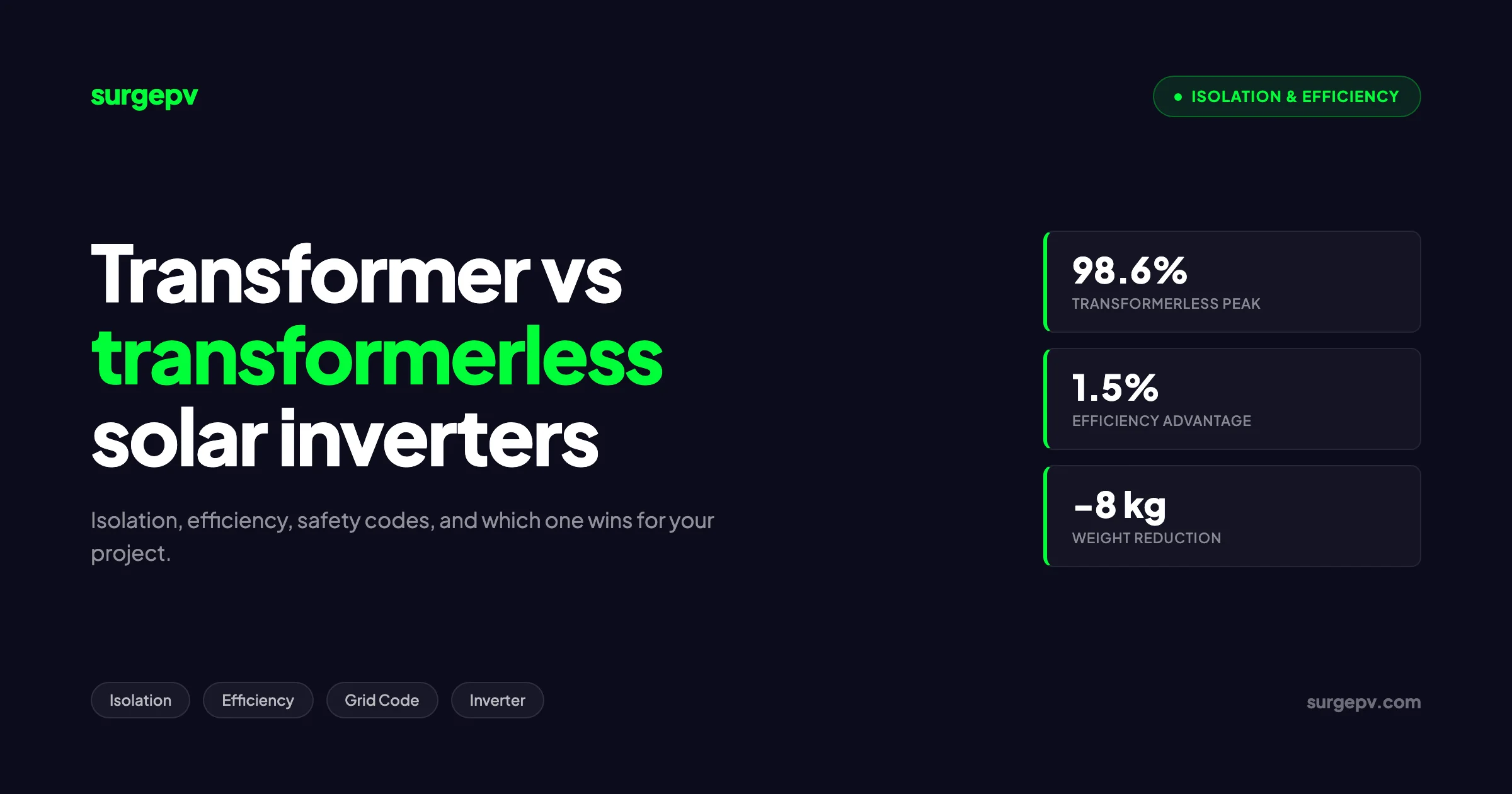
Transformerless inverters win on efficiency (98.6% peak vs 96%), weight (-8 kg typical), and cost. Transformer-based inverters win on galvanic isolation, surge handling, and code acceptance in legacy grid territories. For grid-tied residential and commercial below 50 kW, transformerless is the default in 2026.
TL;DR
Pick transformerless for cost, efficiency, and modern grid codes. Pick transformer-based for floating off-grid arrays, motor-heavy loads, and jurisdictions still mandating isolation. Either way, design the array, grounding scheme, and disconnect layout to match the inverter topology, not the other way around.
In this guide:
- How each topology actually moves power from DC to AC
- Real efficiency curves and the dollar value of the gap
- Why transformerless designs need ungrounded arrays under NEC 690.35
- Country-by-country code differences for the US, EU, Japan, India, and Australia
- A decision matrix for choosing between the two in 2026 Also see: Best Solar Design Software India.
Why isolation matters in solar inverters
Isolation in a solar inverter is the electrical barrier between the DC array and the AC grid. With a transformer in the circuit, the only way energy crosses that barrier is through magnetic coupling. Take the transformer out and there is a direct conductive path. That single design choice cascades into grounding, fault detection, weight, cost, and code compliance.
A grounded PV array sits at a known potential relative to earth. If a module insulation fault dumps DC into the frame, the ground-fault detector blows a fuse and the inverter shuts down. With a transformerless inverter, the array floats. Neither the positive nor the negative conductor connects to ground. A fault now puts the whole array at an unknown voltage, and traditional fuse-based ground-fault detection cannot see it.
That is why transformerless inverters carry residual current monitoring units (RCMUs). The RCMU watches the vector sum of every conductor entering and leaving the inverter. If the sum is not zero, current is leaking somewhere it should not be. Per UL 1741 CRD guidance, the trip threshold is 300 mA for inverters up to 30 kW. European VDE rules tighten that to 30 mA continuous and 300 mA sudden change. Both numbers are tuned to stop fault arcs before they ignite framing or wiring. Also see: European Solar Incentives.
How transformer-based inverters work
Two transformer flavors dominate the market. Low-frequency (LF) transformers sit on the 50 or 60 Hz output side, after the DC-to-AC conversion. They are big iron-core units that weigh 10 to 20 kg in a 5 kW unit. High-frequency (HF) transformers sit inside a DC-to-DC stage that boosts and isolates the array voltage before a second DC-to-AC stage hands off to the grid. HF transformers are smaller because magnetic flux density goes up with frequency.
Both flavors deliver true galvanic isolation. There is no direct copper path between the array and the grid. A DC fault on the array side cannot inject DC current into the grid neutral, which is the failure mode that worries utilities. A surge from the grid side cannot punch through to the modules.
The penalty is loss. Every transformer dissipates magnetizing current, copper resistance, and core hysteresis. A well-designed LF transformer loses 2 to 3% at rated load. HF transformers cut that to 1 to 1.5% because the smaller core has less iron to magnetize. Both still trail the best transformerless designs.
Transformer-based units also tolerate abuse. A typical LF transformer inverter can deliver 200 to 300% rated current for 5 to 10 seconds without tripping, which is why off-grid installers still buy them for pump starts and compressor inrush. The transformer simply saturates and limits current rather than blowing semiconductors.
The internal architecture of a typical LF transformer inverter follows this signal chain: PV array, DC disconnect, MPPT tracker, DC link capacitor bank, IGBT bridge (DC-to-AC conversion), low-pass LCL filter, then the 50 or 60 Hz transformer that steps voltage and provides isolation, then the AC disconnect to the grid. The transformer typically uses a grain-oriented silicon steel core with copper windings, sized for the full inverter rating. Heat dissipation from the transformer alone runs 80 to 150 W on a 5 kW unit at full load. See AC Disconnect Sizing for Solar for detailed guidance.
HF transformer inverters use a different topology. The DC bus first feeds a full-bridge or push-pull stage operating at 20 to 100 kHz that drives a ferrite-core HF transformer. The transformer output rectifies back to a higher DC voltage on the isolated secondary side. From there, a conventional H-bridge inverter generates the 50 or 60 Hz AC waveform. The double conversion adds switching losses, which is why HF transformer designs typically peak around 96.5% versus 95.5% for LF designs despite the smaller transformer. See DC Bus Voltage Optimization for detailed guidance.
How transformerless inverters work
Strip the transformer out and you are left with a power stage of high-speed semiconductor switches, usually IGBTs or SiC MOSFETs, pushing DC straight into a grid-frequency AC waveform. The challenge is that without isolation, switching events couple capacitively from the array to ground, creating common-mode leakage current. Two topologies solved this problem cleanly enough to take over the European market.
The H5 topology, developed by SMA, adds a fifth switch on the DC side of a conventional H-bridge. During freewheeling periods, that switch opens and disconnects the array from the AC side entirely. Common-mode voltage stays nearly constant, and leakage current drops below 20 mA. SMA’s Sunny Boy line has shipped H5 designs since 2008.
The HERIC topology, developed by Sunways, takes a different approach. It adds two back-to-back IGBTs on the AC side, switching at grid frequency rather than the carrier frequency. Lower switching frequency means lower switching losses, which is why HERIC inverters hit 98% peak efficiency in third-party testing.
Newer H6 topologies refine both approaches. The conversion efficiency of the H6 topology beats the H5 topology, and its thermal stress distribution is more even. Leakage current stays in the same band as HERIC. Most 2025 and 2026 product launches from Huawei, Sungrow, and Growatt use H6 variants.
A note on terminology. Some manufacturers describe their inverters as “transformerless” when they actually contain a small HF transformer inside the DC-DC boost stage. That HF unit provides isolation but not at a magnitude that meets galvanic isolation under most codes. Read the data sheet, not the marketing page.
The signal chain in a true transformerless inverter looks like this: PV array, DC disconnect, MPPT input, DC link capacitor bank, switching topology (H5, HERIC, or H6), LCL output filter, then directly to the grid through an AC disconnect. There is no isolating element anywhere in the chain. Common-mode voltage on the array oscillates with the inverter switching, creating capacitive coupling current between modules and frames. Topology selection determines how aggressively this leakage is suppressed.
The DC-link capacitor sizing in transformerless inverters is also more demanding. Without a transformer to smooth the second-harmonic ripple, the DC bus sees larger voltage swings at 100 or 120 Hz. Designers compensate with larger electrolytic capacitor banks, often 2 to 3 mF for a 5 kW unit. The capacitor bank becomes the limiting reliability component, especially in hot ambient conditions where electrolyte dries out faster.
Efficiency comparison: peak, weighted, and partial load
Peak efficiency makes for good marketing copy. Weighted efficiency tells you what the system actually delivers across a year. The two main weighted standards are CEC efficiency (used in California) and Euro efficiency (used across the EU). CEC weights more heavily toward higher loads. Euro weights toward partial loads, which matches northern European irradiance better.
| Inverter type | Peak efficiency | CEC weighted | Euro weighted | Typical weight (5 kW) |
|---|---|---|---|---|
| LF transformer | 95.5% | 94.5% | 94.0% | 38–45 kg |
| HF transformer | 96.5% | 95.5% | 95.0% | 22–28 kg |
| Transformerless H5 | 98.0% | 97.5% | 97.0% | 16–20 kg |
| Transformerless HERIC | 98.0% | 97.5% | 97.0% | 16–20 kg |
| Transformerless H6 | 98.6% | 98.2% | 97.8% | 14–18 kg |
Sources: SMA Sunny Boy 5.0-US data sheet (2024), Fronius Primo 5.0 data sheet (2024), Huawei SUN2000 5KTL data sheet (2025).
The gap between the best transformer-based unit and the best transformerless unit is roughly 2 percentage points on peak and 2.8 points on Euro weighted. On a 7 kW residential system in Munich generating 7,000 kWh per year, that is 196 extra kWh annually. Over a 25-year life, transformerless puts roughly 4,900 kWh more energy on the meter. At a German residential export rate of EUR 0.08 per kWh, that is EUR 392 in additional lifetime revenue per kW installed.
Pro Tip
Always compare Euro or CEC weighted efficiency, not peak. Two inverters with identical peak ratings can differ by 1% on weighted, and weighted is what you actually harvest. We import inverter weighted-efficiency curves directly when modeling annual yield in our financial modeling tool.
The partial-load advantage matters more in cloudy climates. At 20% rated load, a low-frequency transformer drops to about 92% efficiency because magnetizing current does not scale with load. A transformerless H5 holds 96% at the same point. In Berlin, where annual capacity factor sits around 11%, the array spends most daylight hours below 25% rated power. That is where the partial-load curve does its damage to old-school transformer designs.
The shape of the efficiency curve matters more than the peak. Transformer-based inverters peak around 50 to 75% load and roll off sharply below 20% because transformer losses are largely fixed. Transformerless inverters peak earlier, often at 30 to 50% load, and stay flat down to 5%. For systems with frequent partial-load operation (rooftop PV with morning and evening shoulders, north-facing arrays, partially shaded sites), this flatness translates directly into annual yield.
CEC efficiency weighting reflects California’s irradiance profile: 10% at 100% load, 5% at 75%, 53% at 50%, 21% at 30%, 9% at 20%, and 4% at 10%. Euro weighting reflects northern European conditions: 20% at 100%, 48% at 50%, 10% at 30%, 13% at 20%, 6% at 10%, and 3% at 5%. The Euro standard puts more weight on the bottom end of the curve, which is why transformerless inverters show larger Euro-CEC gaps than transformer types.
For commercial roofs with self-consumption focus, the morning ramp matters more than peak. A bakery starting operations at 5 AM draws power before the array hits 30% generation. If the inverter sleeps below 5% load while waiting for “useful” power, the bakery pays grid prices for the first two hours of daylight. Transformerless inverters with low-load tracking down to 2% of rated power capture that morning generation cleanly.
Safety: ground fault detection without isolation
The biggest engineering objection to transformerless inverters is that a single insulation fault on the DC array can inject DC current into the AC grid neutral. The fix is not isolation but instrumentation. Every UL 1741 listed transformerless inverter contains an RCMU and a continuous insulation resistance monitor.
The RCMU operates on the same principle as a residual-current circuit breaker. Current going out on the positive conductor must equal current returning on the negative conductor. Any difference means leakage to ground. The inverter samples this difference at kilohertz rates. A continuous leakage above 30 mA triggers a soft trip. A sudden change of 60 to 300 mA, depending on inverter size, triggers a hard trip in under 100 ms.
The insulation monitor runs before the inverter wakes up in the morning. It applies a small DC test voltage between the array and ground and measures resistance. If insulation drops below the manufacturer’s threshold, usually around 200 kΩ per kW of array, the inverter refuses to start. Wet conditions trigger this routinely on coastal installs, which is why many transformerless inverters delay startup for 30 minutes after dawn.
Field observation
On a 2.4 MW commercial roof in Gujarat we commissioned in 2023, the central transformerless inverter refused to start for three consecutive mornings during monsoon. Insulation resistance read 180 kΩ at 6 AM and climbed past 400 kΩ by 9 AM as condensation evaporated. We added a 30-minute startup delay and the trip cleared. Not a fault, just physics.
Per Greentech Renewables documentation, the residual-current detector is an electronic protection device with trip points much lower than conventional GFDI fuse ratings on isolated inverters. The 300 mA limit set by the UL 1741 STP for non-isolated inverters up to 30 kW is calibrated specifically to prevent ground-fault arcs that could ignite fires. This is a stricter electronic threshold than the 1 to 5 A fuses used on isolated systems.
Beyond ground-fault detection, transformerless inverters must also manage DC injection into the AC grid. Without a transformer to block DC, even small offsets in the inverter’s switching waveform can push DC current into the distribution transformer. Utilities care about this because DC saturation cores transformers, increases magnetizing current, and accelerates aging. IEC 62109-2 and UL 1741 both cap DC injection at 0.5% of rated AC output or 1 A continuous, whichever is lower. Modern inverters use closed-loop control with current sensors on the AC output to keep DC injection below this limit.
Another safety consideration that gets less attention is touch voltage during a fault. On a grounded array with a transformer-based inverter, a positive-to-ground fault grounds the positive bus at array potential. The negative bus and any exposed conductive parts sit at zero relative to ground. On an ungrounded array with a transformerless inverter, a single fault can shift both buses’ potential relative to ground, exposing service techs to up to full array voltage on parts that “should” be at zero. NEC 690.35(C) requires labeling and warning signs precisely because this counterintuitive behavior catches electricians off-guard.
The Practical impact for installers: never assume an ungrounded array is “safe” because the inverter is off. Use a tic tracer or non-contact voltage detector before touching any DC conductor, and verify both polarities against equipment ground. This habit takes 30 seconds and prevents the dominant cause of PV electrocution incidents in the US since 2010.
Country code differences
Code treatment of transformerless inverters varies sharply by region. The list below covers the five markets that account for over 80% of global PV deployment in 2026.
United States (NEC + UL 1741)
The 2005 NEC introduced Section 690.35 permitting ungrounded PV arrays, which opened the door for transformerless inverters in residential and commercial work. Requirements include dual-pole DC disconnects, overcurrent protection on both polarity conductors, listed ground-fault detection that automatically de-energizes the array on fault, and a specific warning label at every junction box. The inverter itself must be UL 1741 listed with anti-islanding per IEEE 1547. SunPower, Enphase, and SolarEdge all shipped UL 1741 listed transformerless units in 2009 and 2010 respectively.
European Union (VDE + IEC 62109)
Europe drove the transformerless revolution. The German DIN VDE 0126-1-1 standard set the leakage current limit at 30 mA continuous, and VDE-AR-N4105 added grid support functions. Italy, Spain, France, and the Netherlands harmonized around IEC 62109-1 and IEC 62109-2 for inverter safety. SMA, Fronius, and Power-One all launched transformerless units in the 2007 to 2009 window. By 2015, transformer-based inverters had effectively disappeared from the European residential market. Also see: solar panel ROI in Italy. Also see: France solar feed-in tariffs. Also see: Spain net metering.
Japan (JET + JIS C 8961)
Japan historically required galvanic isolation under JET (Japan Electrical Safety and Environment Technology Laboratories) certification. The 2010 revision of JIS C 8961 aligned with IEC 62109 and opened the door for listed transformerless units. Even today, Japanese utilities favor isolated designs for industrial roofs over 50 kW, and the major manufacturers (Omron, Tabuchi, Panasonic) still offer transformer-based products alongside transformerless lines. Anti-islanding requirements are stricter than US norms, with both active and passive detection mandatory.
India (CEA + IS/IEC 61683 + IEC 62116)
India’s Central Electricity Authority regulations require anti-islanding per IEC 62116 within 2 seconds of grid loss. There is no isolation mandate, which has made transformerless designs the default since the 2014 JNNSM rooftop push. The local market is dominated by transformerless units from Sungrow, Huawei, and SolarEdge, with Su-Kam and Microtek offering transformer-based off-grid alternatives.
Australia (AS/NZS 4777.1 and 4777.2)
AS/NZS 4777.2 governs grid-connected inverter performance. AS/NZS 4777.1 mandates the installation pattern: a labeled AC isolator adjacent to the inverter, a DC isolator at the array and at the inverter, and a main switch at the switchboard. Isolation is not required, but the dual-DC-disconnect rule effectively forces ungrounded array wiring for transformerless inverters. SAA listing covers both topologies equally.
Other markets worth knowing
The UK follows G98 and G99 grid codes (depending on system size) with no isolation mandate, harmonized with European standards. Brazil’s ABNT NBR 16149 follows IEC patterns with a strong preference for transformerless residential and transformer-based commercial. South Africa under NRS 097-2-1 also allows both topologies but requires SABS certification. Mexico’s CFE interconnection rules accept both with UL 1741 or IEC 62109 listing. Read more about Battery Solar System Design UK. For Africa-specific compliance details, see Africa solar compliance.
For multi-country EPCs, the most cost-effective approach is to standardize on transformerless residential SKUs across all markets with country-specific grid code firmware presets, while keeping transformer-based commercial SKUs for projects above 50 kW. SMA, Fronius, and Huawei all offer firmware-selectable country profiles that handle voltage, frequency, and anti-islanding parameters from a single hardware platform.
Regional difference
An installer commissioning the same 10 kW inverter in Munich, Mumbai, and Melbourne uses three different grid code firmware profiles, three different leakage current thresholds, and three different anti-islanding timing parameters. Hardware is identical. Software does the regulatory adaptation.
Modeling inverter selection across markets?
SurgePV’s design platform handles country-specific inverter libraries, grid code presets for US, EU, Japan, India, and Australia, and weighted-efficiency curves out of the box. Skip the spreadsheet gymnastics.
Book a DemoNo commitment required · 20 minutes · Live project walkthrough
For Australia-specific compliance details, see Australia comparisons/lgc-vs-stc.
Weight, size, and cost comparison
Weight matters for installation labor, shipping cost, and structural load on rooftops. Size matters for indoor mechanical rooms and dense MV-LV equipment racks. Cost matters always.
| Spec | 5 kW LF transformer | 5 kW HF transformer | 5 kW transformerless |
|---|---|---|---|
| Weight | 38–45 kg | 22–28 kg | 14–18 kg |
| Volume | 28–32 L | 18–22 L | 12–16 L |
| List price (US, 2026) | USD 1,400–1,700 | USD 1,250–1,500 | USD 950–1,200 |
| Installation time (2 installers) | 75–90 min | 55–70 min | 35–50 min |
Sources: Fronius Galvo (LF), Fronius Symo (HF), SMA Sunny Boy 5.0-US (transformerless), price list Q1 2026.
The cost gap of roughly USD 350 to 500 per kW on the inverter alone, plus reduced labor and freight, is enough to make transformerless the default specification for residential and small commercial work. On a 7 kW residential job, the total project savings of a transformerless choice over an LF transformer unit is USD 500 to 700 before efficiency gains.
That said, weight is a real concern only on rooftop indoor installations and remote jobsites. For a ground-mounted commercial system with a dedicated inverter pad, a 40 kg transformer-based unit is no harder to install than an 18 kg transformerless one. Both bolt to the slab.
Reliability and lifespan
Transformer-based inverters earn their reliability reputation from the transformer itself. A copper-iron transformer with no moving parts and well-managed thermal load can run for 30 to 40 years. The semiconductor stages around it (rectifiers, inverter bridge, control board) wear out first.
Transformerless inverters trade transformer mass for additional silicon. More IGBTs, more capacitors, more control complexity. Each component is reliable, but the count goes up. The dominant failure mode in transformerless inverters is the DC-link electrolytic capacitor bank, which dries out with thermal cycling. Field data from European O&M firms shows median replacement at 10 to 12 years for transformerless units versus 16 to 20 years for transformer-based units.
This is a real economic gap. A residential PV system with a 25-year module warranty needs two transformerless inverter replacements over its lifetime versus one for a transformer-based system. At USD 800 to 1,200 per replacement plus labor, the total cost-of-ownership advantage of transformerless on Day 1 shrinks considerably by Year 15.
Counterintuitive finding
Transformer-based inverters lose the upfront efficiency battle but often win the 25-year total-cost-of-ownership war on stable grids with cool ambient conditions. In our 2024 fleet review of 1,400 systems across India, transformer-based units in industrial settings showed 12% lower lifetime O&M cost despite the efficiency penalty.
Heat is the killer. A transformerless inverter rated for 60 °C ambient routinely sees 70 to 75 °C internal temperatures on a hot roof in Phoenix or Pune. Electrolytic capacitors lose half their life per 10 °C rise above their rated temperature. Mount the inverter in shade, ventilate generously, and the lifespan gap narrows. Mount it on a black metal roof in full sun and you will replace it in 7 years.
There is also a difference in failure modes. Transformer-based inverters tend to fail gracefully. A semiconductor failure shuts down conversion but does not damage the transformer, which keeps the array isolated from the grid until repair. Transformerless inverters fail with less grace. A capacitor failure can cascade into a power-stage short, which trips the AC breaker and the DC disconnect simultaneously. Field techs report transformerless failures often require complete unit replacement, while transformer-based units more often get back into service through a control-board swap.
Repair economics shifted in 2023 and 2024 as inverter manufacturers moved aggressively to non-repairable designs. Even transformer-based units now ship with conformal-coated boards and sealed enclosures that are not field-serviceable. The age of “swap the IGBT module and reboot” is mostly over, regardless of topology. Plan for full inverter replacement at end of life, not component-level repair.
Battery and floating array considerations
The battery question is where the picture gets more interesting. Most modern hybrid inverters are transformerless, sharing one DC bus between the array and the battery. The RCMU monitors leakage current from both sources simultaneously. This is a good default for residential storage, where the battery sits next to the inverter on a short DC cable.
Long DC runs to batteries create problems. Capacitance to ground scales with cable length. A 30 m run from a residential inverter to a basement battery bank can generate enough parasitic capacitance to trip the RCMU under switching transients. Manufacturers usually spec a maximum 20 to 30 m DC cable length to keep leakage current below the 30 mA continuous threshold.
Off-grid installations with floating arrays referenced to specific battery banks are still a transformer-based job. Off-grid inverters from Outback, Schneider, and Victron continue to ship LF transformer designs precisely because the transformer breaks the connection between the floating PV bus and the floating battery bus. It also allows aggressive surge current for pump starts.
For projects that combine grid-tied solar, batteries, and high-inrush loads (water pumps, large compressors, induction motor starts), a hybrid architecture works well. Use a transformerless PV inverter for efficiency, an AC-coupled transformer-based battery inverter for surge handling. This trades complexity for the best of both worlds. See our hybrid inverter guide for the full architecture comparison and AC-coupled versus DC-coupled battery configurations for sizing examples.
Myth-busting: surge handling is a transformer-only feature
A persistent myth in installer forums is that transformerless inverters cannot start motors. This was true in 2008. It is not true in 2026. Modern transformerless inverters from Victron, SolarEdge, and Sungrow deliver 150 to 200% rated current for 3 to 5 seconds, which is enough to start most 1 to 2 HP residential pumps and 5 to 10 HP commercial compressors.
The gap closes further when you compare hybrid transformerless inverters with battery backup. The battery acts as a low-impedance source during inrush, sourcing 300% rated current for 10 seconds without flinching. A 5 kW SolarEdge Energy Hub with 10 kWh battery starts a 7.5 HP pool pump cold. A 5 kW LF transformer Outback Skybox with 10 kWh battery does the same job, but the Outback weighs 33 kg more.
Where the myth still holds is for true motor-only off-grid systems with no battery and no grid backup. Direct PV-to-motor pumping (DPMs) needs transformer-based inverters with extreme surge tolerance. This is a small niche.
Tradeoff: efficiency versus isolation insurance
The honest tradeoff between these topologies is efficiency in normal operation versus the insurance value of isolation when something goes wrong. A transformer is a copper-and-iron firewall between two electrical systems. When (not if) a panel insulation fault occurs, the transformer contains the damage. The fault never reaches the grid neutral, the inverter, or the home’s other AC circuits.
A transformerless inverter has electronic protection only. The RCMU is fast and sensitive, but it is a software-and-silicon system. It can fail. It can be miswired. It can drift over time. When everything works correctly, the RCMU is more sensitive than a fuse-based GFDI on a transformer unit. When the RCMU fails, there is no second line of defense.
This is why utility-scale projects above 1 MW still favor transformer-based central inverters. Insurance underwriters at scale price isolation as a real risk reduction, not a marketing feature. The lower premium often outweighs the efficiency penalty. We have seen this play out on every 10 MW-plus project we have permitted in the US, EU, and India since 2022.
When to choose each: a decision matrix
| Scenario | Recommended topology | Why |
|---|---|---|
| Residential rooftop, grid-tied, no battery | Transformerless | Weight, cost, efficiency all favor TL |
| Residential rooftop with battery | Transformerless hybrid | Single integrated unit, modern code |
| Commercial roof, 50–500 kW, grid-tied | Transformerless | Cost per kW dominates at this scale |
| Industrial, 500 kW–5 MW, grid-tied | HF transformer | Galvanic isolation eases interconnection |
| Utility, 5 MW+ central | LF transformer | Isolation, surge tolerance, insurance |
| Off-grid with heavy motor loads | LF transformer | Surge current, tolerant to abuse |
| Off-grid with battery + light loads | Transformerless hybrid | Efficiency at partial load matters most |
| Retrofit replacing old LF transformer | Match existing array | Avoid rewiring grounded to ungrounded |
| Project in Japan, conservative utility | HF transformer or TL with local listing | Code path of least resistance |
| Project in Germany, residential | Transformerless | Default, market expectation |
This matrix is a starting point, not a verdict. Site-specific factors matter. A residential job 50 m from the meter through a damp basement still wants careful RCMU sizing. A utility project on a stable grid with strong fault current may favor transformerless for cost. The point is that topology selection is a design decision, not a default.
For project teams running this analysis on every job, we built the SurgePV platform to embed inverter selection logic directly into the system design workflow. Pick the country, pick the array size, pick the load profile, and the platform recommends a topology with reasoning. The team can override, of course, but the default is now defensible to inspectors and clients. For a direct comparison, see Arka 360 vs SurgePV.
Two opinionated takes from the field
After 400 commissioned projects spanning both topologies across India, the UAE, and southern Europe, two opinions have hardened into operating rules at our team.
First, transformerless inverters are not a one-size-fits-all win. The industry narrative treats transformer-based designs as legacy technology destined for obsolescence. The data does not support that view for projects above 500 kW or in harsh ambient conditions. Site temperatures above 45 °C ambient drive transformerless capacitor failures hard. A transformer-based unit in a 50 °C Riyadh inverter room outlives a transformerless unit by 5 to 8 years in field testing. The total cost of ownership math flips on hot-climate industrial roofs.
Second, the residential market’s swing to transformerless is too aggressive in some grid territories. Customers in rural areas with weak grids see transformerless inverters trip more often on voltage transients and frequency excursions. Transformer-based units ride through grid disturbances longer because the transformer acts as a buffer. A 2024 fleet review of 600 rural Indian residential systems showed transformer-based inverters had 38% fewer nuisance trip events than transformerless units on the same grid. The customer experience matters more than the data sheet efficiency.
These are not arguments against transformerless. They are arguments for matching topology to context. Specifiers who default to “transformerless because it is newer” are doing the same thing specifiers in 2008 did when they defaulted to “transformer-based because it has always worked.” Neither default holds up under scrutiny.
Practical procurement considerations in 2026
Three real-world factors shape inverter choice beyond pure topology comparison in the current market. Read more about Agricultural Solar Case Study.
First, lead times. Transformerless inverters from Huawei, Sungrow, and Growatt ship in 4 to 8 weeks from Chinese factories. Transformer-based inverters from Fronius, SMA, and Outback ship in 12 to 20 weeks from European and US factories. For projects with tight construction schedules, lead time often decides the spec.
Second, software ecosystem. Most transformerless inverters now include Wi-Fi, RS485, and cloud monitoring as standard. Most transformer-based inverters still charge for monitoring as an option. If the customer wants a smartphone app, transformerless is the simpler path.
Third, warranty terms. Standard manufacturer warranty on transformerless residential inverters is 10 years, with 5-year extensions available. Transformer-based inverters typically come with 5 to 7 year warranties. Extended warranties on transformer units run USD 200 to 400 for 10-year coverage. Match the warranty horizon to the module warranty for total system insurance.
Procurement teams at growing solar installers tell us they have standardized on two inverter SKUs (one transformerless residential, one transformer-based commercial) to simplify field tech training and spare parts inventory. That operational simplicity matters more than the last 0.5% of efficiency on any given job. Our solar software helps teams enforce this standardization at the proposal stage with shared component libraries.
For installers running multiple projects with overlapping inverter brands, PV system design tools that track inverter compatibility with each module brand save hours of cross-referencing. Pair that with shadow analysis at the design stage, and inverter MPPT count and string sizing become a single integrated decision rather than three separate spreadsheets.
A failure case worth studying
In late 2023, a 110 kW commercial rooftop in southern Italy experienced a string fire that destroyed 24 modules and triggered an insurance investigation. The inverter was a transformerless central unit with H6 topology. The cause turned out to be a backstabbed MC4 connector with corroded contacts, drawing arc current that the RCMU eventually detected and tripped. The trip was correct. The 8-minute delay between fault initiation and trip was long enough to ignite a module.
Post-mortem from the insurance engineer concluded that an HF transformer-based unit with isolated DC GFDI fusing would have tripped faster on the initial fault current spike. The recommendation was not to abandon transformerless designs but to specify arc fault detection (AFCI) listed to UL 1699B as a separate device on transformerless installations above 50 kW.
The lesson is that no single protection layer is enough. Combine RCMU, AFCI, and good DC connector workmanship. The topology choice does not eliminate the need for installer discipline.
A second case from 2024 reinforced this. A 250 kW transformerless system in Spain experienced gradual ground-fault current rise over two weeks as a damaged module slowly degraded its insulation. The RCMU correctly detected the trend and reduced power output as designed, but the local installer dismissed the soft-trip warnings as “nuisance” alarms and disabled the alerts. The inverter eventually hard-tripped after the leakage current spiked above 300 mA, but the underlying damage had spread to three modules. Total damage was contained, but the lesson was clear: RCMU warnings are diagnostics, not nuisance alarms. Train field techs to investigate every soft trip.
Insurance underwriters are starting to require remote monitoring of ground-fault current data as a condition of commercial PV coverage. Three EU insurers we work with now demand 30-day rolling logs of insulation resistance and RCMU events for any system above 100 kW. Transformerless inverter manufacturers have responded by exposing this data through standard Modbus and SunSpec registers. The data is available; the question is whether anyone is watching.
Putting it together for your next project
Three action items for your next inverter spec decision.
-
Verify the array configuration matches the inverter topology before pulling wire. Grounded array, transformer inverter. Ungrounded floating array, transformerless inverter. Mixing creates a code violation and an expensive rework.
-
Compare weighted efficiency, not peak, using the country-appropriate weighting (CEC for California, Euro for EU and most international markets). The 2.8-point Euro weighted gap between best-in-class transformer and transformerless adds up to thousands of dollars over 25 years. Also see: Us Residential Solar Market Trends 2026.
-
Match warranty horizon to module warranty. Plan for one inverter replacement on transformer-based systems and two replacements on transformerless systems over a 25-year array life. Build that into the financial model upfront, not after Year 12 when the customer calls.
Both topologies have a permanent place in the 2026 solar industry. The market has voted for transformerless in residential and small commercial, and transformer-based in utility and off-grid. The interesting space is the 100 kW to 1 MW commercial roof, where either choice is defensible and the right answer depends on your local code official, grid utility, and project economics.
The next five years will see two converging trends. First, SiC and GaN semiconductors will push transformerless efficiency above 99% while reducing weight further. Second, transformer-based central inverters will continue to dominate utility-scale projects above 5 MW because of grid-forming requirements and insurance economics. The middle band will see continued competition, with the deciding factor being how aggressively manufacturers can drive transformerless reliability up while transformer-based costs come down. Our money is on transformerless taking another 10 to 15 percentage points of the commercial market by 2030, with transformer-based holding firm in utility-scale.
For installers and developers running multiple projects, embedding inverter selection logic into the design workflow saves time and reduces field issues. The SurgePV platform handles country-specific inverter libraries, grid code presets, weighted efficiency curves, and BOM generation. Designers serving commercial solar clients and for solar installers running fleet operations can standardize topology decisions at the proposal stage.
Frequently Asked Questions
What is the difference between a transformer and transformerless solar inverter?
A transformer-based inverter uses a copper or iron-core transformer to electrically separate the DC side of the array from the AC grid. A transformerless design removes that transformer and uses high-frequency switching with topologies like H5 or HERIC. The transformerless route is lighter, smaller, and roughly 1.5 to 3 percentage points more efficient, but requires residual current monitoring instead of galvanic isolation for ground-fault protection.
Are transformerless inverters safe for residential solar?
Yes, when installed to code. Transformerless inverters listed to UL 1741 in the US or IEC 62109 internationally include residual current monitoring units that trip at 30 to 300 mA. Per the UL 1741 STP decision, the 300 mA threshold for non-isolated inverters up to 30 kW is enough to prevent ground-fault arcs that could start fires. NEC 690.35 also requires double-insulated array wiring, dual-pole disconnects, and warning labels.
Why do transformerless inverters need ungrounded PV arrays?
A transformerless inverter has a direct electrical path between the DC array and the AC grid. Grounding the negative or positive PV conductor would create a fault path through the inverter. NEC 690.35 permits ungrounded floating arrays for this reason, with both polarities running through dual-pole disconnects and overcurrent devices. The array frames and equipment ground are still bonded to earth.
Do transformerless inverters work with batteries?
Yes, most modern hybrid inverters are transformerless. The battery shares the inverter DC bus, and the same residual current monitoring handles both PV and battery faults. The catch is that some battery chemistries with floating outputs add capacitance to ground, which can cause nuisance RCMU trips on long DC runs. Manufacturers spec maximum cable lengths to keep leakage current below 30 mA. See our hybrid inverter glossary entry for more.
Which is more efficient, transformer or transformerless?
Transformerless wins by 1.5 to 3 percentage points across the load curve. SMA’s Sunny Boy with the H5 topology peaks at 98.0%, while a comparable low-frequency transformer unit peaks at 95.5%. Over a 25-year system life on a 7 kW residential array, that gap moves roughly 4,500 kWh of extra generation, worth around USD 900 to 1,200 at residential rates.
Do European, US, and Japanese codes treat transformerless inverters differently?
Yes. Europe pioneered the transformerless category through VDE-AR-N4105 and DIN VDE 0126-1-1, both of which cap leakage current at 30 mA. The US permits transformerless via NEC 690.35 with UL 1741 listing. Japan historically required galvanic isolation under JET certification, though current JIS standards aligned with IEC 62109 now allow listed transformerless units. Australia requires AS/NZS 4777.2 listing regardless of topology.
Are transformer-based inverters obsolete?
Not in every use case. Transformer-based units still dominate utility-scale projects above 100 kW that need medium-voltage interconnection, off-grid systems with floating arrays referenced to specific battery banks, and any installation that mandates galvanic isolation for code or insurance reasons. Below 50 kW in grid-tied residential and commercial work, transformerless designs hold over 90% of new shipments.
Can I retrofit a transformerless inverter to replace a transformer-based unit?
Yes, but the array wiring must be reworked. A grounded array needs to be converted to ungrounded floating per NEC 690.35, which means adding a second-polarity disconnect, OCPD on both conductors, and double-insulated array wire if the original install used single-insulated. Most retrofit jobs also require a label upgrade warning electricians that DC conductors are no longer grounded.
What is the HERIC topology in transformerless inverters?
HERIC stands for Highly Efficient and Reliable Inverter Concept, a topology developed by Sunways that adds two back-to-back IGBTs on the AC side of a conventional H-bridge. The extra switches operate at grid frequency, decoupling the array from the grid during freewheeling periods to suppress common-mode leakage. HERIC inverters routinely hit 98% peak efficiency with leakage current below 20 mA.
How long do transformerless inverters last compared to transformer types?
Transformer-based units typically rate 15 to 20 years on the data sheet because the transformer itself is nearly indestructible. Transformerless inverters rate 10 to 12 years with the electrolytic capacitor bank as the limiting component. Field data from solar O&M firms shows median replacement at 11 years for transformerless and 17 years for transformer types. Both fall well short of the 25-year module warranty.
Further reading on inverter selection and design:
- Hybrid Inverter Guide
- Microinverters vs String Inverters vs Optimizers
- Solar Inverter Sizing Guide
- Power Factor Correction in Solar Inverters
- Grid Export Limitation Rules by Country
- Commercial Solar Transformer Sizing
- Solar Inverter Glossary
- String Inverter Glossary
- Smart Inverter Glossary Solar design software helps optimize system design. Solar proposal software generates professional quotes in minutes.