Quick Answer
The 2026 residential solar permit package has more sheets than it did three years ago. NEC 2023 adoption pushed labeling and rapid shutdown diagrams onto separate pages. Roughly 450 AHJs run SolarAPP+ instant approval, which rejects any plan set that deviates from a strict template.
A residential solar permit package gets rejected on the first review more often than it gets approved. The fix is rarely a redesign — it is a missing dimension on the site plan, an OCPD value that does not match the inverter spec sheet, or a fire setback drawn at 18 inches when the local code requires 36. Every drawing in the plan set has a specific role, and the AHJ reviewer is checking each one against a list. This is that list.
The 2026 residential solar permit package has more sheets than it did three years ago. NEC 2023 adoption pushed labeling and rapid shutdown diagrams onto separate pages. Roughly 450 AHJs run SolarAPP+ instant approval, which rejects any plan set that deviates from a strict template.
The 2026 residential solar permit package has more sheets than it did three years ago. NEC 2023 adoption pushed labeling and rapid shutdown diagrams onto separate pages. Battery storage now requires its own sheet under NEC 706. Roughly 450 AHJs run SolarAPP+ instant approval, which rejects any plan set that deviates from a strict template. This guide walks through every required drawing — what goes on each sheet, what reviewers flag, and how to ship a package that clears the first review. For more on this topic, see Adding Battery Storage Services.
TL;DR — Solar Permit Package Checklist
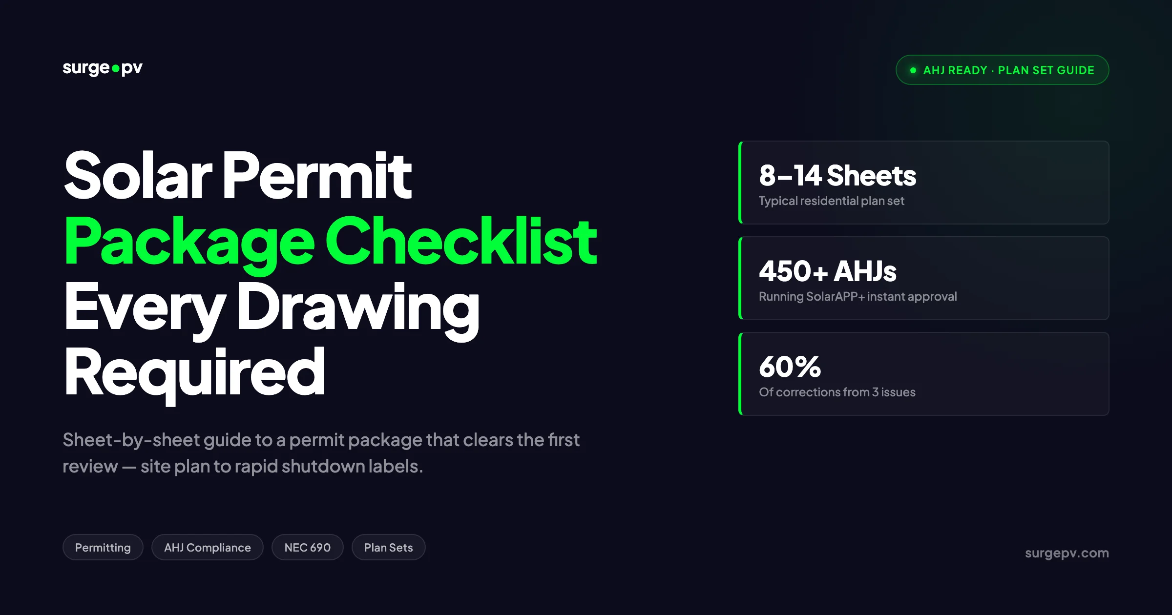
A complete residential solar permit package contains 8 to 12 sheets: cover sheet, site plan, roof layout, single-line diagram, three-line diagram, equipment schedule, structural details, rapid shutdown plan, labeling schedule, and battery sheets if applicable. Roof load calculations, fire setback dimensions, and NEC 690.12 compliance are the three items that cause the most rejections. SolarAPP+ jurisdictions process compliant plan sets in minutes; manual AHJs take 1 to 8 weeks.
What this guide covers:
- Every sheet your AHJ requires, in submission order, with drawing-specific content rules
- NEC 2023 and NEC 2026 changes that affect the permit package
- State-by-state PE stamp requirements
- Top 10 rejection reasons with fixes
- Pre-submittal checklist you can run against any package before upload
What an AHJ Actually Reviews in Your Solar Permit Package
The Authority Having Jurisdiction — usually a city or county building department — has two reviewers on every solar permit. The plans examiner checks code compliance and structural safety. The electrical reviewer checks NEC compliance and one-line accuracy. Each one runs your plan set against a printed checklist that mirrors their state amendments to NEC, IRC, IBC, and the local fire code.
The plans examiner cares about three things: the PV array fits inside the buildable roof area after fire setbacks, the structure can carry the added dead load and wind uplift, and the roof penetrations are detailed correctly. The electrical reviewer cares about correct wire and OCPD sizing, a clean grounding path, NEC 690.12 rapid shutdown compliance, and proper labeling.
Anything outside those bounds — like a battery system, a service panel upgrade, or a ground mount — pulls in a third reviewer. This is why permit packages have grown longer. Every additional scope item demands its own sheet.
The reviewer is not designing the system. The reviewer is checking that your design matches the code. Your job as the designer is to make every required check easy to find. A plan set that hides information across multiple sheets gets rejected even when the design is correct, because the reviewer does not have time to hunt for it. Ship a plan set that answers every checklist question on the right sheet, in the right order, with the right callouts.
For more on how AHJs operate and what jurisdiction-specific quirks affect your design, see the AHJ glossary entry and the AHJ compliance guide.
The Complete Sheet List: Every Drawing Required
A residential PV permit package without battery storage runs 8 to 10 sheets. Add a battery system or panel upgrade and you push to 12 to 14. The order below mirrors what most AHJs and SolarAPP+ expect.
| Sheet | Title | Purpose |
|---|---|---|
| PV-0 | Cover Sheet & General Notes | Project metadata, codes, sheet index, scope |
| PV-1 | Site Plan | Property boundaries, structure, array footprint |
| PV-2 | Roof Plan | Module layout, fire setbacks, attachments |
| PV-3 | Single-Line Diagram | Electrical schematic, OCPD, conductors |
| PV-4 | Three-Line Diagram | Phase detail, grounding, MLPE detail |
| PV-5 | Equipment Schedule | Modules, inverter, racking, MLPE |
| PV-6 | Structural Details | Attachment, flashing, connection schedule |
| PV-7 | Rapid Shutdown & Placards | NEC 690.12 layout, label schedule |
| PV-8 | Cut Sheets | Manufacturer datasheets, UL listings |
| PV-9 | Battery Layout (if applicable) | NEC 706 compliance, ESS placement |
| PV-10 | Service Panel Upgrade (if applicable) | New panel detail, busbar rating |
The sheet numbering above is convention, not a requirement. Some AHJs renumber as E-1, A-1, S-1 across electrical, architectural, and structural disciplines. Use whatever convention the AHJ publishes. What matters is that every required topic appears on its own sheet with a consistent title block.
The next sections walk through each sheet — what the reviewer is checking, what must appear, and the callouts that prevent a correction notice.
Cover Sheet & General Notes (Sheet PV-0)
The cover sheet is the first thing the reviewer sees. It sets the tone and answers three questions before the body of the plan set even opens: who designed this, what code edition does it claim compliance with, and what is the project scope.
Required Elements
Project information block. Owner name, project address, APN or parcel number, utility account number, system size in kW DC and kW AC, and the AHJ name. The interconnection application number goes here when available.
Designer and contractor information. Company name, license number, contact information, designer name, and PE stamp area if required by the state.
Code references and design standards. List every applicable code with edition: NEC 2023 (or 2020 / 2017 depending on AHJ), IRC 2021, IBC 2021, ASCE 7-22, and CRC for California. Add local amendments if the AHJ publishes them. Some jurisdictions like Los Angeles County have specific Title 24 references that must appear on the cover.
Sheet index. Every sheet listed by number, title, and revision date. The index lets the reviewer cross-reference quickly and confirms no sheets are missing.
General notes. A 10 to 20 line block covering: scope of work, voltage and phase, all conductor types and insulation ratings, conduit specifications, grounding method, working clearances per NEC 110.26, and any inspection requirements. Generic notes are fine — the reviewer wants to see them present, not original.
Title block. Repeats on every sheet. Project address, sheet number, sheet title, designer name, revision number, date, and PE stamp area. The title block is the most-flagged item on the cover sheet because it must match exactly across all pages.
Common Cover Sheet Errors
| Error | Fix |
|---|---|
| Wrong NEC edition cited for the AHJ | Check the AHJ’s published code adoption page before listing |
| Missing APN or parcel number | Pull from county assessor’s website before drafting |
| System size in DC only, no AC | Always show both — kW DC and kW AC at standard inverter rating |
| Sheet index does not match sheets in the file | Cross-check after every revision |
A modern solar design software with permit output handles most of this automatically — the project metadata propagates from the customer record into the title block, and the code reference list updates based on the project ZIP code. The same metadata flows through to solar proposal software for the customer-facing financial package.
Site Plan (Sheet PV-1)
The site plan is the only drawing that shows the project in the context of the property. The reviewer is checking three things: the structure footprint matches the parcel, the array location is approximately correct, and access for emergency responders and meter readers is preserved.
Required Site Plan Content
North arrow and scale. Always present, in the same corner on every site-level drawing. Common scale is 1” = 20’ for residential lots; larger for commercial.
Property boundary. Drawn from the recorded plat or from a recent survey. Show all dimensions on at least two sides.
All structures on the parcel. Main dwelling, detached garage, sheds, pool equipment, and any outbuildings. Show roof outlines, not just floor plates.
Driveway, walkways, and street access. The fire department needs to see how the responder reaches the structure.
Utility infrastructure. Service drop or underground service, meter location, main service panel, and any subpanels. Mark the new AC disconnect location and the rapid shutdown initiator. Read AC Disconnect Sizing for Solar for a complete walkthrough.
The PV array footprint. Shown as a polygon on the roof of the structure. Dimensions to property lines if any zoning setback might apply.
Address callout. The street address printed clearly so the inspector matches the right house.
Legend. Symbols for new equipment, existing equipment, and demolition.
Setback and Zoning Notes
Some AHJs require zoning setbacks on the site plan even when the array is fully on the existing structure. California has tighter setback rules near tribal lands and coastal zones. Florida adds wind exposure category callouts. Check what the AHJ publishes — every published checklist line maps to one drawing element.
For ground-mount systems, the site plan does double duty as the foundation layout and is one of the most heavily reviewed sheets. The full guide for ground-mount work is in ground-mount solar design.
Roof Plan & Array Layout (Sheet PV-2)
The roof plan is where most permit corrections happen. The reviewer is checking module placement against fire setbacks, structural attachment alignment with rafters, and electrical pathway from the array to the inverter location.
What the Roof Plan Must Show
Roof outline with all ridges, hips, valleys, eaves, and rakes labeled. Every roof segment used by the array needs orientation and pitch labeled. Pitch in degrees, orientation in compass azimuth.
All roof obstructions. Vents, plumbing stacks, HVAC penetrations, skylights, chimneys, and dormers. Every obstruction requires a 18” clear setback on residential systems unless local fire code says otherwise.
Fire setbacks dimensioned. Standard residential setbacks under IFC 2021:
- 3 feet on both sides of the ridge for a single-ridge roof
- 18 inches on rakes for systems with one access pathway
- 4 feet of clear access pathway for at least one side from eave to ridge
- Larger setbacks may apply on multi-family or larger structures
Some jurisdictions allow reduced setbacks when the modules use a UL 7103 fire classification or when the home has automatic fire sprinklers. Note any reduction with the code reference.
Module layout. Every module shown to scale, with row spacing, edge-of-roof distance, and module count per array. Group strings if applicable.
Attachment points. Show every standoff or rail attachment with rafter alignment. The reviewer needs to confirm the load path goes from module to rail to standoff to rafter to wall plate.
Conduit pathway. Draw the DC conduit run from array to inverter, showing transitions through attic, exterior wall, or roof penetration. Mark conduit size and fill compliance.
Inverter and disconnect locations. Show the inverter mounting location, the AC disconnect, and the rapid shutdown initiator. Include working clearance per NEC 110.26.
Roof material callout. Comp shingle, metal seam, tile, slate. Different roof types have different attachment standards and flashing requirements. For metal roofs, see the standing seam attachment standards in the metal roof solar mounting guide.
Roof Plan Rejection Triggers
| Issue | What Happens | Fix |
|---|---|---|
| Modules within 18” of an obstruction | Correction notice | Increase setback or move obstruction (rare) |
| Ridge setback drawn at 18” not 36” | Rejection | Verify local fire code; default to 36” residential |
| No rafter alignment shown | Plans examiner red mark | Show every standoff aligned to a rafter centerline |
| Skylight not labeled as smoke vent | Fire department rejection | Label every skylight as smoke vent if applicable |
Modern solar design software with auto-layout handles fire setbacks dynamically — drag the setback offset and the array reflows in seconds. Manual CAD draftspersons spend 30 to 60 minutes per design getting the offsets right.
Single-Line Diagram (Sheet PV-3)
The single-line diagram (SLD) is the electrical reviewer’s primary document. It collapses all current paths into one line per circuit. If the reviewer cannot trace power flow from the array to the utility meter on the SLD, the package gets rejected.
Required Single-Line Components
PV array block. Shows total module quantity, module model, total array DC voltage at STC, total array DC current, and Voc at minimum design temperature.
Module-level power electronics block. If the design uses microinverters or DC optimizers, show the MLPE quantity, model, and per-unit specs.
Combiner box (if applicable). Show input circuits, total output current, OCPD rating, and conductor size.
DC disconnect. Required for string inverter systems. Show ampere rating, voltage rating, and location callout.
Inverter. Model, AC output voltage and current, OCPD on the AC output side.
AC disconnect. Outdoor, lockable, visible from the service equipment. NEC 690.13.
Service panel and main breaker. Show busbar rating, main breaker rating, and the backfeed breaker for the solar circuit. NEC 705.12 governs the 120 percent rule and busbar interconnection.
Utility meter and grid connection. Arrow showing point of common coupling.
Conductor schedule. Every conductor segment labeled with size, type, conduit, and length range. Include voltage drop calculations referenced from this sheet.
OCPD schedule. Every overcurrent protective device with rating, type, manufacturer, and AIC rating.
Grounding and bonding. Equipment grounding conductor size, GEC size if applicable, and bonding to the existing grounding electrode system per NEC 250.
Single-Line Sizing Calculations
The SLD sheet must show the sizing arithmetic, not just the result. Reviewers look for:
| Calculation | Reference | What to Show |
|---|---|---|
| Maximum DC voltage | NEC 690.7 | Voc × cold temp coefficient × module count |
| DC conductor ampacity | NEC 690.8 | Isc × 1.25 × 1.25 (continuous + safety) |
| AC output current | Inverter spec | Continuous AC output ÷ AC voltage |
| AC OCPD | NEC 240.6 | AC output × 1.25, rounded up to standard size |
| Busbar 120% rule | NEC 705.12(B) | Busbar rating × 1.20 ≥ main + backfeed |
Glossary terms relevant here: single-line diagram, NEC Article 690, NEC Article 705, disconnect switch, equipment grounding, conduit fill, and stringing electrical design.
Three-Line Diagram (Sheet PV-4)
The three-line diagram appears on plan sets for systems with batteries, ground mount over 10 kW, three-phase service, or any project where the AHJ requires more electrical detail. For pure microinverter residential systems on single-phase service, some AHJs accept the SLD alone.
What the Three-Line Adds
Each phase conductor drawn separately. Phase A, Phase B, neutral, and ground each shown as their own line.
Per-phase grounding paths. Equipment grounding from each device back to the grounding electrode.
MLPE detail at module level. Microinverters or optimizers shown with their AC or DC output back to the trunk cable.
Bonding jumpers and grounding electrodes. Every connection point that bonds metal parts to the grounding system.
Transformer detail. Required when the design includes an autotransformer for 240/120 split phase from a single-phase inverter, or for any commercial 480V system.
The three-line is where many corrections appear because reviewers expect specific symbology. Use ANSI Y32.2 standard symbols. Custom symbols cause confusion.
Equipment Schedule & Cut Sheets (Sheets PV-5 and PV-8)
The equipment schedule is a tabular summary of every component in the system. The cut sheets are the manufacturer datasheets that prove the equipment is listed and rated for the application.
Equipment Schedule Format
A clean schedule lists each equipment type as a row with the following columns: equipment name, manufacturer, model, quantity, key electrical ratings, and certification listings.
| Equipment | Manufacturer | Model | Qty | Rating | Listing |
|---|---|---|---|---|---|
| PV Module | [Maker] | [Model] | 24 | 410 W, 41.5 Voc | UL 61730 |
| Microinverter | [Maker] | [Model] | 24 | 295 W AC | UL 1741 |
| Combiner Box | [Maker] | [Model] | 1 | 60 A | UL 1741 |
| AC Disconnect | [Maker] | [Model] | 1 | 60 A, 240 V | UL 98 |
| Racking | [Maker] | [System] | — | UL 2703 | — |
| Rapid Shutdown | [Maker] | [Model] | 1 | UL 1741 | — |
Cut Sheet Requirements
The cut sheet packet contains the manufacturer-published datasheet for every line on the equipment schedule. Reviewers check three things on each cut sheet:
- The model number matches the schedule exactly
- The UL listing or other certification is visible
- The electrical ratings used in the SLD calculations match the datasheet
Print every cut sheet at 100 percent — never reduce to fit. Reviewers scan the listings and ratings and reject when text is too small to read.
For racking and ballasted systems, include the UL 2703 listing and the Class A fire rating documentation. For modules, the UL 61730 listing and IEC 61215 listing if available. For inverters, UL 1741 and the IEEE 1547 conformance.
Structural Documentation (Sheet PV-6)
Structural documentation is the most jurisdiction-variable piece of the package. Some AHJs accept a generic structural letter signed by a PE. Others require full load calculations stamped by a state-licensed engineer.
Standard Structural Sheet Content
Roof framing plan. Existing rafter or truss layout with size, spacing, and span. If the existing framing is unknown, the structural assessment should call this out and recommend an attic inspection before installation.
Attachment detail. A scaled detail showing the standoff, the lag screw, the flashing, and the connection to the rafter. This is the single most-detailed drawing in the package because it shows exactly how the array load transfers to the structure.
Connection schedule. A table listing every connection: lag screw size, embedment depth into rafter, edge distance, and the shear and pullout strength. The schedule references ASCE 7-22 wind loads and IBC 2021 dead load combinations.
Load calculations. Worksheet showing dead load (modules and racking, typically 3 to 4 psf), live load (snow where applicable), and wind load (uplift based on wind exposure category, mean roof height, and roof zone). The calculation must show the existing roof can carry the new combined load — typically expressed as the new total dead load is below the design dead load capacity of the structure.
Wind zone exposure. Show the wind exposure category (B, C, or D), the design wind speed (90 to 180 mph depending on location), and the roof zone (interior, edge, corner). Edge and corner zones have higher uplift coefficients. ASCE 7-22 changed several coefficients from ASCE 7-16 — check which edition the AHJ has adopted.
Snow load callout. Required wherever ground snow load exceeds 20 psf. Include the IBC 1608 sloped roof snow load calculation.
For the full structural ballast methodology on flat roofs, see the flat roof ballasted solar systems guide. For slate roof attachment specifics, see the slate roof solar panel design.
When a PE Stamp Is Required
Roughly half of US states require a PE stamp on residential solar structural calculations. The thresholds vary:
| State | Residential PE Stamp Required? | Threshold |
|---|---|---|
| California | No, with exceptions | Required if roof slope >7:12 or unusual structure |
| Texas | No | Generic letter accepted |
| Florida | Yes | Required statewide for residential rooftop |
| New York | Yes | Required for any rooftop PV |
| Massachusetts | Yes | Required by state code |
| Arizona | No, generally | Some AHJs require it |
| Colorado | Varies by AHJ | Denver and Boulder require; many others do not |
| Illinois | No | Generic structural letter accepted |
| New Jersey | Yes | Required for residential and commercial |
| Pennsylvania | Yes | Statewide |
The state with the strictest stamp rules is Massachusetts, which requires both a structural and electrical PE stamp on every residential rooftop system. The lightest is Texas, where most AHJs accept a contractor-signed structural letter for systems on conventionally framed roofs.
Verify each AHJ before submission. The list above is a starting point — local amendments override state rules.
Rapid Shutdown Compliance & NEC 690.12 (Sheet PV-7)
NEC 690.12 is the rapid shutdown rule. It exists for firefighter safety. Every PV system on or in a building in the US must comply, and the permit package must show how.
What 690.12 Requires
PV systems on or in buildings must reduce DC voltage to safe levels within 30 seconds of a rapid shutdown initiation. The thresholds:
- Inside the array boundary (within 1 foot of the array edge): 80 V or less within 30 seconds
- Outside the array boundary: 30 V or less within 30 seconds
The shutdown initiator must be visible, accessible, and at a known location — typically near the AC disconnect or service equipment.
Compliance Pathways
There are two common ways to comply:
Module-Level Power Electronics (MLPE). Microinverters or DC optimizers placed at every module collapse the DC voltage to safe levels at the module itself when the inverter or initiator de-energizes. This is the dominant residential approach and is fully NEC 690.12 compliant.
UL 3741 PV Hazard Control System. A system-level approach that uses a string inverter without per-module electronics but adds hazard control hardware that satisfies the firefighter touch-voltage criterion at the array level. Less common for residential but growing.
Required Drawings on the Rapid Shutdown Sheet
Array boundary diagram. Plan view showing the array edges with a 1-foot offset polygon. This defines the inside vs outside boundary for the voltage thresholds.
Initiator location callout. Photograph of the proposed initiator location, dimension to ground, and accessibility notes. Most AHJs want the initiator at the rapid shutdown switch label, not buried inside an electrical room.
Initiator method. Describe the initiator: a dedicated rapid shutdown switch, a manual disconnect, or an integrated function within the AC disconnect.
MLPE schedule. Quantity, manufacturer, model, and the UL listing certifying NEC 690.12 compliance.
Wiring detail. Show the trunk cable from MLPE units back to the inverter or recombiner. Note that the AC trunk on microinverter systems is energized any time grid power is present and is therefore subject to standard NEC AC wiring rules.
Rapid Shutdown Placard Specifications
The 2023 NEC moved the building placard from 690.56(C) to 690.12(D). The current spec:
- Building placard: minimum 4 in × 6 in, located at the service equipment
- Switch placard: minimum 1 in × 4 in, red background with white reflective letters, located at the initiator
- Text: “PHOTOVOLTAIC SYSTEM EQUIPPED WITH RAPID SHUTDOWN” and “TURN RAPID SHUTDOWN SWITCH TO THE OFF POSITION”
The 2023 edition relaxed the color requirement on the building placard but kept the switch placard as red-with-white. Earlier NEC 2017 and 2020 jurisdictions still require red-with-white on both. Check which edition the AHJ has adopted.
For the deeper code primer, see rapid shutdown and NEC 2026 solar changes.
Generate Permit-Ready Plan Sets in One Click
SurgePV builds the full permit package — site plan, roof layout, single-line diagram, equipment schedule, and labeling sheet — directly from the design. The output matches SolarAPP+ format and standard AHJ templates.
Book a DemoNo commitment required · 20 minutes · Live project walkthrough
For a direct comparison, see Arka 360 vs SurgePV.
Battery Storage Sheets (Sheet PV-9)
Battery storage adds 2 to 4 sheets to the permit package and triggers NEC 706 review. Half of residential solar permits in 2026 include battery storage, so most installers should treat this as standard scope.
Required Battery Sheet Content
Battery placement plan view. Show the ESS location with dimensions to walls, doors, windows, and combustible materials. NEC 706.4 and NFPA 855 require minimum separation distances and a maximum aggregate energy rating per location.
Ventilation and clearance details. Most lithium-ion residential batteries require minimum 3 ft of working clearance in front and 6 inches around the unit. Verify against the manufacturer-published install manual.
Battery single-line addition. Show the battery system on the SLD with its dedicated DC or AC bus, the battery disconnect, the battery management system communication path, and the inverter or hybrid inverter connection.
Energy storage system schedule. Manufacturer, model, capacity in kWh, voltage, and the UL 9540 system listing.
Fire detection and suppression. If the battery is installed inside a garage or attached structure, NFPA 855 may require a smoke detector or sprinkler. Note the AHJ’s interpretation.
ESS placard. Per NEC 706.7, an additional placard at the service equipment identifies the energy storage system, total capacity, and shutdown procedure.
Battery Permit Rejection Triggers
| Issue | Fix |
|---|---|
| Battery within 3 ft of an exit door | Relocate or use an outdoor enclosure |
| No NFPA 855 separation distances called out | Add dimension callouts on the placement plan |
| Aggregate energy exceeds 20 kWh in one location | Split across two enclosures or relocate one |
| Battery disconnect not shown | Add to SLD and equipment schedule |
For the full residential battery sizing methodology, see the battery solar system design UK guide — the engineering principles apply across markets even though the regulatory references differ. See our guide on Heritage Building Solar Case Study for more. For United Kingdom-specific compliance details, see United Kingdom comparisons/mcs-vs-non-mcs.
Service Panel Upgrade & Interconnection Sheets
When the existing service panel cannot accommodate the solar backfeed under NEC 705.12, a panel upgrade is part of the scope and adds its own sheet to the package.
What the Service Upgrade Sheet Shows
Existing panel detail. Manufacturer, model, busbar rating, main breaker, current load, available breaker space.
New panel detail. Manufacturer, model, new busbar rating (typically 200 A or 225 A), new main breaker, busbar 120 percent calculation showing the solar backfeed fits.
Service entrance detail. New service conductors, meter base, grounding electrode system, and the service mast or underground service entrance.
Working clearance per NEC 110.26. Dimensioned to walls and obstructions.
Interconnection Application Reference
Most utilities require an interconnection application before issuing utility approval, and most AHJs require the interconnection application number on the cover sheet before permit approval. The flow:
- Submit the interconnection application to the utility (PG&E, SCE, ConEd, etc.)
- Receive the application number — usually within 1 to 5 business days
- Add the application number to the cover sheet of the permit package
- Submit the permit package to the AHJ
- Once permit is approved and system is installed, schedule the utility witness test or remote PTO
For more detail on the interconnection workflow, see interconnection agreement, grid interconnection application, and interconnection documents.
Labeling & Placard Schedule
NEC requires a long list of labels on every PV system. The placard schedule is a single sheet — usually combined with the rapid shutdown sheet — that lists every required label, where it goes, and the exact text.
Standard Residential Solar Label Set
| Label | Location | Code Reference | Text |
|---|---|---|---|
| PV system identification | Service equipment | NEC 690.13(B) | “PHOTOVOLTAIC POWER SOURCE” |
| Maximum AC operating current | AC disconnect | NEC 690.54 | ”MAX OCPD = X A; AC OUTPUT = Y A” |
| Maximum DC voltage | DC disconnect | NEC 690.53 | ”MAX DC VOLTAGE = X V” |
| Rapid shutdown switch | At initiator | NEC 690.12(D)(2) | Red w/ white text, “TURN OFF” |
| Rapid shutdown building placard | Service equipment | NEC 690.12(D)(3) | Building rapid shutdown notice |
| AC disconnecting means | AC disconnect | NEC 690.13 | ”PV SYSTEM AC DISCONNECT” |
| DC disconnecting means | DC disconnect | NEC 690.15 | ”PV SYSTEM DC DISCONNECT” |
| Inverter location | Service equipment | NEC 705.10 | Directory of all sources |
| Backfed breaker warning | Service panel | NEC 705.12 | ”DO NOT RELOCATE THIS BACKFED BREAKER” |
| Bidirectional warning (if applicable) | Combiner or inverter | NEC 705 | Bidirectional power source |
| Battery system identification | Battery + service | NEC 706.7 | ESS identification placard |
The labels must be permanent — engraved, etched, or printed on weather-rated material. Self-adhesive paper labels do not pass field inspection.
State PE Stamp Requirements: Quick Reference
PE stamp requirements are state-level rules that override AHJ preference. The table above covers the structural side. For electrical PE stamps, the rules are different and tighter.
| State | Electrical PE Stamp Required for Residential? |
|---|---|
| California | No (with rare exceptions) |
| Texas | No |
| Florida | Yes |
| New York | Yes |
| Massachusetts | Yes |
| Connecticut | Yes |
| New Jersey | No, but commercial yes |
| Pennsylvania | Yes |
| Colorado | No |
| Illinois | No |
| Arizona | No |
| Washington | No |
| Oregon | No |
Commercial projects (anything above 25 kW DC in most states) almost always require both a structural and electrical PE stamp. Always verify against the current state engineering board rule before quoting a project.
Top 10 Solar Permit Rejection Reasons
Every reviewer keeps a mental top-10 list. The same issues appear over and over. Knowing them in advance is the cheapest way to ship cleaner permit packages.
-
Fire setback dimensions wrong or missing. Default residential setbacks: 36” ridge, 18” rake, 36” hip. Verify against the local fire code.
-
OCPD rating does not match inverter spec sheet. AC output × 1.25 rounded up to next standard size. Cross-check the SLD against the inverter cut sheet.
-
Structural calculation does not address wind uplift. Required in every jurisdiction with ASCE 7 adoption — that means everywhere.
-
Single-line diagram missing the grounding electrode conductor. GEC size and routing must appear on the SLD.
-
Equipment schedule does not match cut sheets. Model numbers, ratings, and listings must agree exactly.
-
No interconnection application number. Increasingly common rejection in California, New York, Massachusetts, and Texas.
-
Title block inconsistent across sheets. Address, designer, date, or revision differs sheet to sheet.
-
Roof material not labeled. Comp shingle, metal, tile, slate. Different materials trigger different attachment standards.
-
Working clearance not dimensioned. NEC 110.26 requires 36” depth × 30” width × 78” height clear at every disconnect and panel.
-
Rapid shutdown initiator not visible from service equipment. NEC 690.12(D)(2) requires the initiator to be “readily accessible” — buried inside a garage closet does not pass.
The fix for all 10 is the same: a pre-submittal checklist run against the AHJ’s published guidelines. The next section provides a generic version.
Pre-Submittal Checklist (Use Before Every Upload)
Run this 30-item checklist before every permit submission. It catches roughly 80 percent of common rejection reasons.
Cover Sheet
- Project address matches APN and county records
- Designer name, license, and PE stamp area present
- All applicable codes listed with edition number
- Sheet index matches the actual sheets in the file
- Interconnection application number present (if available)
Site Plan
- North arrow and scale shown
- Property boundary fully dimensioned
- All structures shown including detached buildings
- Driveway and street access shown
- Service equipment location marked
Roof Plan
- Fire setbacks dimensioned per local fire code
- Every obstruction shown with 18” minimum offset
- All roof segments labeled with pitch and azimuth
- Roof material called out
- Conduit pathway from array to inverter shown
- Inverter and disconnect locations marked
- Working clearance dimensioned
Single-Line Diagram
- Every conductor labeled with size, type, conduit, and length
- Every OCPD shown with rating and AIC rating
- Maximum DC voltage calculation shown with cold temp coefficient
- AC output current calculation shown
- Busbar 120 percent calculation per NEC 705.12
- Grounding electrode conductor shown
Equipment & Cut Sheets
- Equipment schedule lists every component
- Cut sheets attached for every line in the schedule
- Model numbers match exactly between schedule and cut sheet
- UL listings visible on every cut sheet
Structural
- Roof framing layout shown with rafter size and spacing
- Attachment detail with lag size, embedment, and edge distance
- Wind uplift calculation per ASCE 7-22
- Snow load shown if applicable
- PE stamp present if state requires
Rapid Shutdown & Labels
- Array boundary diagram with 1-foot offset
- Initiator location dimensioned and accessible
- All required NEC labels listed in placard schedule
- Building placard and switch placard specs called out
A modern solar software platform with permit output runs most of these checks automatically. The remaining manual checks should take a designer 5 to 10 minutes per package.
SolarAPP+ vs Manual AHJ Review
NREL’s SolarAPP+ platform changed how residential permits get reviewed. Over 450 AHJs run it as of 2026, and approval times for compliant packages drop from weeks to minutes.
How SolarAPP+ Works
SolarAPP+ is an automated permit issuance tool. The installer uploads a structured digital plan set — not a PDF, but a JSON-format design with specific fields. The tool runs the design against:
- NEC 2020 or 2023 (configurable per AHJ)
- IRC 2021
- ASCE 7-22 wind and snow loads
- Local fire code
If every check passes, the permit issues immediately — typically in under 5 minutes. If any check fails, the tool returns specific error codes and the installer fixes and resubmits.
What SolarAPP+ Approves Automatically
- Residential PV systems up to 38.4 kW DC
- Battery storage up to a defined capacity
- Combined PV-plus-storage installations
- Service panel upgrades on supported configurations
What Still Goes Through Manual Review
- Ground-mount systems
- Commercial PV
- Multi-family residential
- Any project that exceeds the 38.4 kW threshold
- Projects in AHJs that have not adopted SolarAPP+
Manual AHJ Timeline by Region (2026)
| Region | Typical Timeline | Notes |
|---|---|---|
| California | 1–4 weeks | Fast where AB-379 enforcement is strong |
| Arizona | 1–3 weeks | Tucson and Phoenix particularly fast |
| Texas | 1–6 weeks | Wide variance — Austin fast, smaller AHJs slow |
| Florida | 2–6 weeks | PE stamp adds time |
| New York | 3–8 weeks | Especially long in NYC |
| Massachusetts | 4–10 weeks | Both PE stamps required |
| Colorado | 1–3 weeks | Mostly digital review |
| New Jersey | 3–6 weeks | Tight code review |
| Illinois | 2–5 weeks | Chicago longer |
| Northwest | 1–4 weeks | Mostly digital, fast |
The fastest path to PTO is a SolarAPP+ jurisdiction with a strong utility automated interconnection process. The slowest is a manual AHJ in a state with both PE stamp requirements.
Conclusion: Three Action Items
-
Build a pre-submittal checklist for every AHJ you work in. Save the AHJ’s published guidelines as a PDF in your project folder. Cross-check every permit package against it before upload. The 30-item generic checklist above is a starting point — customize per jurisdiction.
-
Standardize your plan set template across designers. Inconsistent title blocks, sheet numbering, and notes are the most common cause of rejections by reviewers who otherwise approve the underlying design. A shared template inside your solar design platform eliminates this.
-
Submit interconnection applications first, permit packages second. The lag between interconnection submission and approval is shorter than the lag between permit submission and rejection. Front-loading the interconnection number onto the cover sheet kills one rejection reason before it appears.
Permitting is the single longest delay in residential solar after sales. A clean plan set on the first submission accelerates everything downstream — installation scheduling, utility approval, and final PTO. The drawings above are the standard. Build them right once and reuse.
Frequently Asked Questions
What drawings are required in a solar permit package?
A complete residential solar permit package includes a cover sheet with general notes, site plan, roof plan with array layout, electrical single-line diagram, three-line diagram for systems with batteries or larger arrays, equipment cut sheets, structural attachment details, roof load calculations, rapid shutdown labeling diagram, and a placard schedule. Most AHJs also require an interconnection application reference and a stamped structural letter when the array exceeds load thresholds.
How long does it take to get a residential solar permit approved?
AHJs running SolarAPP+ approve eligible residential systems in minutes. Manual review jurisdictions take 1 to 8 weeks, with the national median sitting near 3 weeks for residential PV. California, Arizona, and Texas average the fastest manual timelines. Northeast and Midwest AHJs run longer, especially for systems with battery storage or service upgrades.
Does every solar permit package need a PE stamp?
No. Roughly half of US states require a Professional Engineer stamp on residential structural calculations, and a smaller subset require it on the electrical plan set. California, Texas, and Florida do not require a PE stamp on standard residential rooftop systems unless the AHJ specifically asks. Commercial projects nearly always require both a structural and electrical PE stamp.
What is the most common reason solar permits get rejected?
Missing or incorrect fire setbacks on the roof plan, followed by incomplete single-line diagrams missing OCPD ratings, and structural calculations that do not address wind uplift. Roughly 60 percent of permit corrections are caused by these three issues combined. The fix is a pre-submittal checklist run against the AHJ’s published guidelines.
What is NEC 690.12 and why does it appear on every permit package?
NEC 690.12 is the rapid shutdown rule. It requires PV systems on or in buildings to drop DC voltage to safe levels within 30 seconds of a shutdown signal. The permit package must show how the system complies, identify the initiator location, and include the red rapid shutdown placard at the service disconnect. Almost every AHJ in the US enforces this section.
Can I submit a solar permit without an interconnection application?
Increasingly, no. Most major utilities now require the interconnection application number to appear on the permit plan set, and AHJs in California, New York, Massachusetts, and Texas refuse to issue final approval without it. Submit the interconnection application first, then reference the application number on the cover sheet.
What software do solar designers use to produce permit-ready plan sets?
Most residential installers use a single platform that handles design, structural calculations, and plan set output. SurgePV produces full AHJ-ready PDFs including site plan, roof layout, single-line diagram, equipment schedule, and labeling sheet from one project file. The output formats match SolarAPP+ requirements and standard utility templates.
How do I check if my AHJ uses SolarAPP+?
Search the SolarAPP+ jurisdiction directory at solarapp.nrel.gov or check the AHJ’s building department website. Over 450 jurisdictions have adopted SolarAPP+ as of 2026. If your AHJ is on the list, eligible residential systems under 38.4 kW DC can receive instant approval once the digital plan set passes the automated check.
Sources
- NREL SolarAPP+ program data — automated permit adoption and timeline statistics
- NEC 2023 Article 690 — solar photovoltaic systems requirements
- NEC 2023 Article 706 — energy storage systems requirements
- ICC IRC 2021 and IFC 2021 — residential code and fire code references
- ASCE 7-22 — minimum design loads for buildings and other structures


