Quick Answer
Arc Fault Circuit Interrupters (AFCIs) detect dangerous DC arc faults in solar systems. NEC 690.11 requires AFCI protection for PV systems on dwellings. Series arcs (loose connections) and parallel arcs (damaged conductors) are detected by analyzing high-frequency noise. AFCI devices cost $50–$200 and are integrated into modern inverters.
A DC series arc fault burns silently within normal operating current limits, invisible to every fuse and breaker in the system. Unlike a ground fault or short circuit, it produces no excess current — just a self-sustaining plasma channel that carbonizes insulation and roofing material until the structure ignites or the circuit physically fails.
Arc Fault Circuit Interrupters (AFCIs) detect dangerous DC arc faults in solar systems. NEC 690.11 requires AFCI protection for PV systems on dwellings. Series arcs (loose connections) and parallel arcs (damaged conductors) are detected by analyzing high-frequency noise.
Arc Fault Circuit Interrupters (AFCIs) detect dangerous DC arc faults in solar systems. NEC 690.11 requires AFCI protection for PV systems on dwellings. Series arcs (loose connections) and parallel arcs (damaged conductors) are detected by analyzing high-frequency noise. AFCI devices cost $50–$200 and are integrated into modern inverters.
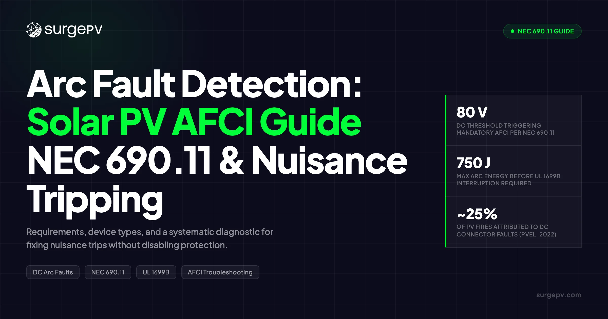
Arc-fault circuit interrupters (AFCI) exist specifically to catch what conventional overcurrent protection misses. NEC 690.11 has mandated them on DC PV circuits since 2011, and the code has tightened in every cycle since. Yet nuisance tripping — where the AFCI interrupts a circuit with no real fault present — remains one of the most common field complaints from solar installers.
This guide covers both sides of the problem: what NEC 690.11 actually requires and which systems are exempt, how DC arc faults differ physically from AC faults, what UL 1699B demands from listed devices, how to choose between device types, and a systematic method for diagnosing and fixing nuisance trips without compromising safety.
TL;DR — AFCI in Solar PV
NEC 690.11 requires arc-fault protection on DC PV circuits operating at 80 V or more on or in buildings. The device must be listed to UL 1699B — not UL 1699, which covers AC systems only. Ground-mounted systems in metallic raceways and microinverter systems below 80 V DC are exempt. Most nuisance trips trace back to poor MC4 crimps, loose terminals, or outdated firmware — not a faulty AFCI. Never disable arc-fault protection to stop nuisance trips.
In this guide:
- Why DC arc faults are more dangerous than AC faults — and why fuses cannot stop them
- Solar fire data: what Fraunhofer ISE, NREL, and PVEL field inspections actually show
- NEC 690.11 requirements across the 2011–2023 code cycle, and which systems are exempt
- UL 1699B test parameters every designer should know
- Integrated inverter AFCI vs standalone combiner-box AFCI vs microinverter exemption — comparison matrix
- The six most common nuisance trip causes and a systematic fix for each
- Design decisions that cut arc fault risk before installation begins
Why DC Arc Faults Are Different — and More Dangerous
An AC arc fault extinguishes itself 120 times per second at the natural zero-crossing of the sine wave. A DC arc fault has no zero-crossing. Once the plasma channel forms, the PV array — behaving as a near-constant-current source under irradiance — continues feeding energy into the arc indefinitely.
That makes DC arc faults in PV systems dangerous in 3 specific ways.
First, they are self-sustaining. The ionized plasma channel has lower resistance than air, so the arc persists and grows once established. The plasma reaches temperatures high enough to carbonize insulation, mounting hardware, and roofing material within seconds. Read Solar Racking Design Guide for a complete walkthrough.
Second, they are invisible to overcurrent protection. A series arc fault — the most common type, caused by a loose connector or broken conductor — does not increase current above the normal operating range. Fuses and breakers see nothing unusual and stay closed.
Third, the available voltage is more than sufficient to sustain arcs in typical residential systems. String inverter systems commonly operate at 400–1,000 V DC. An arc’s sustaining voltage (roughly 20–40 V) is a small fraction of string voltage, so the source continues driving current through the fault regardless.
| Attribute | DC Arc Fault (PV System) | AC Arc Fault |
|---|---|---|
| Zero-crossing | None — arc is self-sustaining | Extinguishes 120×/sec at zero-crossing |
| Current source behavior | Near-constant current feeds arc continuously | Grid voltage drops at zero-crossing |
| Visibility to fuses/breakers | Series arcs stay within normal current band — invisible | More likely to exceed breaker threshold |
| Detection difficulty | High-frequency noise is a fraction of the DC signal | Larger signature relative to waveform |
| Arc energy available | High string voltage (400–1,000 V) sustains arc | Lower sustained energy due to cycling |
Arc Energy Formula
Arc Energy (J) = Arc Voltage (V) × Arc Current (A) × Duration (s). A series arc at 30 V and 9 A sustained for 2 seconds produces 540 J. NEC 690.11 requires interruption within 2.5 seconds; most modern AFCI devices respond in under 500 ms.
Solar Arc Fault Fire Data
US solar fire statistics are fragmented — the NFIRS has no dedicated solar fire code, so USFA data substantially underreports incidents. The data that does exist points consistently at arc faults and installation quality as primary culprits.
| Source | Data Point | Period |
|---|---|---|
| U.S. Fire Administration | 56 solar system fires recorded in 2018, up from 25 in 2015 (PV Magazine USA, Aug 2019) | 2015–2018 |
| Fraunhofer ISE | ~350 fires in over 1.4 million installations = 0.006% incidence; system at fault in 120 cases (Fraunhofer ISE, 2013) | 20-year retrospective |
| Fire & Rescue NSW (Australia) | 139 solar fires attended in 2020 vs 22 in 2018 — 6× increase while installations roughly tripled (Firetrace International, 2022) | 2018–2020 |
| PVEL | DC connectors implicated in 24% of PV-caused fires in Germany and 27% in the U.K. (PVEL, 2022) | Field inspections |
Two things stand out in this data. The overall incidence is low — Fraunhofer ISE’s 0.006% figure provides useful perspective for clients. But Australia’s 6× growth in solar fires while installations only tripled points to degrading installation quality across an aging fleet, not any inherent technology problem. See our guide on Solar Energy in Australia for more. For Australia-specific compliance details, see Australia comparisons/lgc-vs-stc.
What the Data Means for Installers
DC connectors are implicated in roughly 25% of solar fires. The root cause in most cases is installation quality: poor crimps, loose terminals, and mismatched connector brands. AFCI devices catch what those errors eventually produce. Better installation quality reduces both real fires and the nuisance trips that follow from poor workmanship.
NEC 690.11 Requirements — What the Code Actually Says
When AFCI Is Mandatory
NEC 690.11 applies to DC PV source circuits and output circuits operating at 80 V or more that are installed on or in a building. This covers any conductors that penetrate a building structure — not only those mounted on the roof surface.
When a fault is detected, the system must do 3 things:
- Interrupt PV system operation (stop current flow)
- Provide a visual indication — a fault code or physical alarm
- Require manual restart — automatic restart after an arc detection event is prohibited under NEC 690.11
The AFCI device must be listed to UL 1699B. Devices listed only to UL 1699 (the AC branch-circuit standard) do not satisfy NEC 690.11 requirements.
NEC Edition Evolution
| NEC Edition | Key Requirement | Notable Change |
|---|---|---|
| 2011 (690.11) | Arc-fault circuit protection required on DC PV source/output circuits on or in buildings | First introduction of DC AFCI mandate |
| 2014 (690.11) | Detection + interruption within 2.5 s; UL 1699B listing required | Added response time limit |
| 2017 (690.11) | Maintained 2014 requirements | Clarified visual indication requirements |
| 2020 (690.11) | Functionally grounded systems included | Removed exemption for certain grounded system configurations |
| 2023 (690.11) | Enhanced detection requirements | Tightened coordination with rapid shutdown (690.12) and ground fault (690.41) |
Most US jurisdictions have adopted NEC 2020 or 2023, though some states and counties remain on earlier editions. Always verify the adopted edition with the local authority having jurisdiction (AHJ) before finalizing a design.
Systems Exempt from NEC 690.11
3 categories of systems are exempt:
Ground-mounted systems where all DC output circuits are in metallic conduit, metal-clad (MC) cable, enclosed cable trays, or underground installations — and the system does not penetrate a building.
Microinverter systems operating below 80 V DC per module. Enphase microinverters operate at under 60 V DC per module. No high-voltage DC string wiring exists on the roof.
PV equipment enclosures used solely to house PV equipment are not classified as “buildings” for purposes of the exemption — but this does not create a blanket ground-mount exemption for rooftop systems.
Pro Tip
Always confirm which NEC edition your AHJ has adopted before designing. Some jurisdictions still enforce NEC 2017 or earlier, which have different requirements for certain grounded system configurations. Pull the permit application checklist for the specific AHJ first.
UL 1699B — The DC AFCI Standard
UL 1699B — Standard for Photovoltaic (PV) DC Arc-Fault Circuit Protection — is the listing standard for NEC 690.11-compliant AFCI devices. It is specific to DC PV systems and is not interchangeable with UL 1699, which covers AC branch-circuit AFCI.
Key Test Parameters
| Parameter | UL 1699B Requirement |
|---|---|
| Maximum arc energy accumulation | Less than 750 J |
| Required interruption time | Less than 2.5 seconds |
| Minimum detectable arc power | 300 W or greater (per original UL 1699B-2011 scope) |
| Detection frequency range | 1 kHz – 100 kHz (broadband spectral analysis) |
| Arc type tested | Series arc (most common field fault type) |
| Manual restart requirement | Yes — automatic restart after arc detection is prohibited |
How Detection Works
AFCI devices monitor DC current for high-frequency noise superimposed on the DC waveform. An arc produces broadband chaotic noise across the 1 kHz–100 kHz range — a signature that looks nothing like normal inverter switching transients or MPPT sweeps.
The discrimination algorithm must reject false positives from:
- Inverter switching transients (PWM frequencies typically 4–20 kHz)
- MPPT perturb-and-observe sweeps
- Rapid irradiance changes at cloud edges
- Power-line communication signals used for smart meter communication
This discrimination is where older or poorly tuned devices fail. They either miss slow-developing faults or trip on normal operating conditions.
International Equivalents
| Standard | Region | Relationship to UL 1699B |
|---|---|---|
| IEC 63027 | International | Published 2023; harmonized with UL 1699B |
| AS/NZS 5033:2019 | Australia / New Zealand | References UL 1699B technical requirements |
| CSA C22.2 No. 292 | Canada | Requires manual restart; UL 1699B alone does not guarantee CSA compliance |
| PEC § 6.90.5 | Philippines | Mirrors NEC 690.11; references UL 1699B |
Types of AFCI Devices for Solar
Integrated Inverter AFCI
Most modern string inverters sold in the US market include AFCI detection circuits as standard. The inverter’s onboard DSP monitors DC input current using spectral analysis, opens a relay or stops conversion on detection, and logs the event.
Major inverters with integrated, UL 1699B-listed AFCI:
- SolarEdge HD-Wave (3000H and above): AFCI enabled by default on DSP1 firmware v1.210.787+ (single-phase) / v1.13.702+ (three-phase)
- SMA Sunny Boy US series: Requires manual restart after arc detection per NEC 690.11 (no auto-restart)
- Fronius Primo, Symo, GEN24 Plus, Verto Plus: Standard on current production
- Huawei SUN2000 series: Integrated detection
- Sungrow SG series: Available on most current models
Advantages: No additional hardware cost. Self-test on startup. Automatic code compliance on new installations.
Limitations: Protection covers only the circuit between combiner box and inverter. A fault in string wiring upstream of the combiner may not be detected until arc noise reaches the inverter input. Inverter switching frequencies can also overlap the detection band.
Standalone Combiner Box AFCI
A dedicated detection module installs in the DC combiner box or within 6 ft of it, monitoring individual string circuits independently of the inverter.
Common devices:
- Sensata PVAF-T / PVAF-R: Thread-through current sensor + normally closed switch output
- Eaton PV ARCI Detector Module: Type 1 standalone
- E-T-A PVSEC-AF1: Integrated rapid shutdown + AFCI disconnect switch
- Mersen arc-fault disconnect combiners: Commercial scale, 250 A+
Cost: $200–400 per device (as of May 2025). This adds to installed cost but provides broader coverage than integrated inverter AFCI alone.
Advantages: Protects the full DC circuit including string wiring. Works with older inverters via retrofit. Operates independently of inverter switching noise.
Limitations: Additional hardware and wiring connections. The device must be specifically listed for use with the inverter in the system.
Module-Level AFCI (Microinverters and Power Optimizers)
Enphase microinverters operate below 60 V DC per module — below the 80 V threshold of NEC 690.11. No separate DC AFCI device is required. The AC conductors from the microinverter to the panel are subject to standard AC AFCI requirements under NEC Article 210.
SolarEdge power optimizers reduce DC voltage to approximately 1 V per module on any shutdown event (SafeDC). The AFCI detection circuit still resides in the inverter. Optimizers reduce available arc energy during shutdown but do not substitute for AFCI during normal operation. Read DC Bus Voltage Optimization for a complete walkthrough.
Tigo TS4 modules provide module-level rapid shutdown. Arc fault detection typically relies on inverter-integrated AFCI.
Comparison Matrix
| Attribute | Integrated Inverter AFCI | Standalone Combiner AFCI | Microinverter (below 80 V DC) |
|---|---|---|---|
| Added cost | Included in inverter price | +$200–400 per device | MLPE premium ~$0.20–0.30/W |
| Protection coverage | Combiner → inverter only | Full string → inverter | No DC AFCI required |
| Retrofit to existing system | No (requires inverter replacement) | Yes | Requires MLPE swap |
| Nuisance trip exposure | Moderate (inverter switching noise) | Lower (independent sensor) | Not applicable |
| Manual restart required | Yes | Yes | N/A |
| Best fit | New residential string systems | Commercial or inverter retrofit | Complex or shaded residential roofs |
Common Causes of AFCI Nuisance Tripping in Solar
Nuisance tripping — the AFCI interrupts the circuit with no real arc fault present — is the most frequent installer complaint about DC AFCI systems. Understanding the cause matters more than the symptom.
Installation-Quality Causes
| Cause | Mechanism | Field Frequency |
|---|---|---|
| Poor MC4 connector crimps | Intermittent high-resistance contact creates noise in the detection band | Most common |
| Loose screw terminals | Thermal cycling opens micro-gaps; contact resistance fluctuates and generates noise | Very common |
| Mixed connector brands | Mismatched mating surfaces increase contact resistance | Common |
| Improper torque on terminals | Under-torque creates arcing micro-gaps; over-torque cracks connector housings | Common |
The majority of nuisance trips trace back to these 4 causes. A connector that passes visual inspection can still fail a pull test or show elevated contact resistance on a milliohm meter.
Electrical and Environmental Causes
Electromagnetic interference (EMI): Inverter PWM switching, variable-frequency drives in nearby HVAC equipment, radio transmitters, and other high-frequency sources inject noise onto DC wiring that AFCI algorithms can misread as an arc signature.
Capacitive coupling: Long parallel DC cable runs — especially homeruns exceeding 30 m (100 ft) — create distributed capacitance between conductors. Current imbalances from this capacitance can trigger detection algorithms.
Inrush current and MPPT transients: Capacitor charging at inverter startup or rapid MPPT sweep steps cause sudden current changes that overlap the detection window on older algorithm implementations.
Rapid irradiance changes: Cloud-edge transients cause sharp, step-function changes in irradiance. Some early AFCI implementations could not distinguish these from arc signatures.
Firmware and Hardware Causes
Inverter manufacturers continuously refine AFCI detection algorithms through firmware updates. A system commissioned on 2019-era firmware may have a detection algorithm with a significantly higher nuisance trip rate than the current release. This is one of the most underutilized diagnostic levers available to field technicians.
AFCI module incompatibility across brands is a separate cause: a detection board certified for one inverter model may generate nuisance trips when paired with a different model because switching noise profiles differ.
Never Disable AFCI to Stop Nuisance Trips
Disabling arc-fault protection violates NEC 690.11, voids the equipment warranty, and removes the only protection against DC arc fault fires. The correct response to nuisance trips is a systematic diagnostic — starting with connectors and firmware — not disabling safety protection.
Design Systems That Pass Inspection the First Time
SurgePV’s solar design software helps you plan optimal string configurations, DC run lengths, and combiner locations — reducing arc fault risk before installation begins.
Book a DemoNo commitment required · 20 minutes · Live project walkthrough
For a direct comparison, see Arka 360 vs SurgePV.
How to Troubleshoot and Fix AFCI Nuisance Trips
Work through these steps in order. Skipping to firmware updates before checking connectors wastes time and misses the most common cause.
Step 1 — Verify Legitimate vs Nuisance Trip
Before assuming nuisance, check for physical evidence of a real arc: melted plastic housing on MC4 connectors, blackened contacts, charred insulation, or discoloration around junction box entries. If any physical evidence exists, the trip is legitimate. Repair the fault before restarting the system.
Only proceed to Steps 2–6 if there is no physical evidence after multiple trips.
Step 2 — Inspect and Re-crimp Connectors
Re-crimp MC4 pins using the connector manufacturer’s specified crimp tool and die — not a universal tool. Perform a pull test on every connection; it should withstand at least 50 lbs tensile force without separating. Verify the audible click of the locking mechanism. If contact resistance measurement is available, use a milliohm meter — elevated readings indicate a poor crimp even when the connection looks visually correct.
Never mix MC4 connectors from different manufacturers. Stäubli, Amphenol, and Multi-Contact all have slightly different internal geometry. Mismatched pairs create high-resistance mating surfaces that mimic arc signatures.
Step 3 — Torque Check All Terminals
Terminal torque that is too low creates micro-gaps that arc on thermal cycling. Too high can crack connector housings or damage terminal threads.
- Module junction box terminals: 1.0–1.5 N·m (verify against module manufacturer spec)
- Combiner box lugs: 7–9 N·m (verify against combiner manufacturer spec)
- Inverter DC input terminals: per inverter manufacturer installation manual
Use a calibrated torque screwdriver. Recalibrate annually.
Step 4 — EMI Mitigation
Route DC homeruns in a separate conduit from AC conductors and motor circuit wiring. In high-EMI environments — commercial HVAC, industrial equipment nearby — route DC wiring in metallic conduit. This provides both physical protection and EMI shielding. Avoid bundling multiple string conductors tightly for long runs.
Ferrite cores on DC conductors entering the combiner box can suppress high-frequency noise in severe cases.
Step 5 — Update Firmware
Check the inverter manufacturer’s support portal for the current firmware release. Manufacturers — SolarEdge, SMA, Fronius, and others — publish AFCI algorithm refinements as part of routine firmware updates. Running firmware that is 2+ years old is a common source of nuisance trips that disappears after an update.
Some inverter models allow configurable AFCI sensitivity. Follow the manufacturer’s commissioning procedure for the site’s EMI environment. Do not increase sensitivity beyond the manufacturer’s recommended range.
Step 6 — Isolate and Swap Strings
If the issue persists after Steps 1–5, isolate strings one at a time by disconnecting them from the combiner or inverter MPPT input. The trip should stop when the problem string is removed. Then swap that string between MPPT inputs: if the fault follows the string, the issue is in that string’s wiring or connectors. If the fault stays with the MPPT input, the problem is in the inverter’s detection circuit for that channel.
| Mitigation Strategy | Application Scenario |
|---|---|
| Upgrade to current-generation AFCI device | Pre-2014 devices had significantly higher nuisance trip rates |
| Shorten DC runs | Longer runs increase noise pickup and impedance |
| Use metallic conduit for homeruns | High-EMI environments; commercial sites near VFDs |
| Add ferrite cores to DC conductors | Severe broadband noise environments |
| Stagger capacitive load startup | Battery inverters or large capacitive loads at startup |
Design Choices That Prevent Arc Faults
The most effective approach is to eliminate arc fault root causes during the design phase.
Connector Quality and Handling
Specify only connectors certified to IEC 62852 or UL 6703. Do not substitute uncertified “MC4-compatible” connectors — their internal geometry and contact plating differ enough to create high-resistance mating surfaces. Never mix brands on a single circuit, even when both are individually certified.
Proper crimping requires the manufacturer-specified crimp tool and die. Every connection requires a pull test. This is not optional on commercial systems.
Wire Management and Routing
Minimize DC run length wherever string layout allows. Every additional meter of cable adds impedance and EMI pickup area. Route DC conductors in metallic raceways where code permits — this provides arc fault protection and physical protection against UV degradation and wildlife damage. Install bushings at all conduit penetrations and roof entry points to prevent chafing.
Using solar design software to model string layouts before installation lets you compare run lengths across layout options and identify the configuration that minimizes DC homerun distance.
System Architecture Choices
| Design Decision | Risk Reduction |
|---|---|
| Microinverters (below 80 V DC) | Eliminates high-voltage DC string wiring; no NEC 690.11 AFCI required |
| Shorter string configurations | Lower string voltage reduces available arc energy; shorter high-voltage runs |
| Power optimizers + rapid shutdown | Reduces DC voltage to safe levels on shutdown; limits arc energy in a fault |
| Enclosed combiner boxes with IP65+ rating | Prevents moisture ingress that corrodes terminals and initiates parallel arcs |
A shadow analysis at the design stage can identify shading conditions that push you toward module-level power electronics — which also resolves AFCI compliance for complex roof configurations.
Commissioning and Ongoing Maintenance
At commissioning, perform insulation resistance testing with a megohmmeter. Minimum acceptable readings: 1 MΩ for residential, 2 MΩ for commercial. A value below these thresholds indicates insulation damage that will eventually produce either a ground fault or an arc fault.
Annual thermal imaging of all combiners, inverter DC input terminals, and module junction boxes identifies high-resistance hot spots before they arc. Many commercial O&M contracts include IR scanning as a standard annual deliverable.
Retorque all terminals after the first year. Thermal cycling from day/night temperature swings causes connections to loosen over the first 12 months of operation.
The generation and financial tool can model the financial cost of an extended outage from an AFCI-detected fault, giving clients context for why installation quality matters over the system’s lifetime.
Pro Tip
Include AFCI commissioning verification in your startup checklist. Confirm the inverter displays “AFCI active” or equivalent status at startup self-test. For standalone combiner AFCI devices, verify the LED or digital output indicates normal operation. Document the result in the commissioning report — some AHJs and utility interconnection agreements require it.
Frequently Asked Questions
Is AFCI required for solar panels?
Yes, for most residential and commercial string inverter systems. NEC 690.11 requires arc-fault circuit protection on all DC PV source and output circuits operating at 80 V or more that are installed on or in a building. Ground-mounted systems in metallic raceways, underground conduit, or enclosed trays are exempt if they do not penetrate the building. Microinverter systems operating below 80 V DC per module are also exempt.
What causes AFCI nuisance tripping on solar systems?
The most common cause is poor MC4 connector crimps that create intermittent high-resistance contacts mimicking arc signatures. Other causes include: loose screw terminals at combiner boxes or module junction boxes, mixed-brand connectors with mismatched mating surfaces, long DC wire runs picking up electromagnetic interference, inverter switching transients overlapping the AFCI detection frequency band (1 kHz–100 kHz), and rapid irradiance changes from cloud-edge transients. Outdated inverter firmware with poorly tuned detection algorithms also contributes.
What is the difference between AFCI and GFCI in solar?
AFCI detects high-frequency noise signatures from arcing in wiring and connections — it protects against fire. GFCI detects current imbalance between supply and return conductors caused by current leaking to ground — it protects against electrocution. NEC Article 690 requires both: AFCI under Section 690.11 for DC circuits above 80 V on buildings, and ground-fault protection under Section 690.41. They detect completely different fault types and are not substitutes for each other.
Do microinverters need AFCI?
No. Microinverter systems like Enphase operate at less than 60 V DC per module — below the 80 V threshold that triggers NEC 690.11. High-voltage DC string wiring is eliminated and no separate DC AFCI device is required. The AC wiring from the microinverter to the panel is subject to standard AC AFCI requirements under NEC Article 210.
What is UL 1699B?
UL 1699B is the safety standard for photovoltaic DC arc-fault circuit protection. NEC 690.11 requires that any AFCI device used on a solar system be listed to UL 1699B — not UL 1699, which covers AC systems only and is not interchangeable. Key requirements: arc energy accumulation below 750 J, interruption within 2.5 seconds, and arc detection at 300 W or more.
How do I stop my solar inverter from tripping AFCI?
Work through a systematic checklist. First, inspect all MC4 connectors and terminals for physical damage and re-crimp any that fail a pull test. Second, verify torque on all terminals with a calibrated screwdriver. Third, update inverter firmware. Fourth, isolate strings one at a time to identify which circuit is triggering. Fifth, route DC wiring away from AC and motor circuits to reduce EMI pickup. Never disable AFCI — this violates NEC 690.11 and removes fire protection.
DC arc faults are the failure mode that conventional overcurrent protection cannot detect. The AFCI mandate in NEC 690.11 exists because no other mechanism catches them.
For designers, the practical approach is to minimize arc fault risk at the source: quality connectors, short DC runs, and system architecture choices that reduce string voltage. Solar software can model string configurations and DC routing before committing to a layout — catching risk factors at the design stage rather than the inspection or O&M stage.
For installers dealing with nuisance trips, the cause is almost always in the connectors or the firmware. Work through the diagnostic in order. If a client asks to disable arc-fault protection to stop false alarms, the answer is no — the liability from a structure fire makes that decision straightforward.
Solar proposal software can document AFCI compliance and equipment specifications in client deliverables, giving residential and commercial customers a clear record of what protection their system includes and why.