Quick Answer
The AC disconnect is one of the most frequently rejected items on solar permit sets. A main disconnect under 690.13 does not satisfy 690.15. Located within the equipment itself (integral disconnect) 2. Located in sight from and readily accessible from the equipment 3. Lockable in the open position per NEC 110.25, where the disconnect is not within sight 4.
The AC disconnect is one of the most frequently rejected items on solar permit sets. Not because the rules are complicated — because most plan sets apply the wrong amperage rating, use an indoor-rated enclosure outdoors, or misread the NEC 690.15(D) distance requirement. Any one of those three errors sends the permit back for a resubmit.
The AC disconnect is one of the most frequently rejected items on solar permit sets. A main disconnect under 690.13 does not satisfy 690.15. Located within the equipment itself (integral disconnect) 2.
This guide covers the full sizing formula, the NEC 690.15 placement rules that changed in the 2023 code cycle, NEMA rating selection by environment, and a complete worked example for a 7.6 kW residential inverter. We also show where solar design software removes the manual sizing step by pulling the disconnect rating directly from the inverter specification.
TL;DR — AC Disconnect Sizing
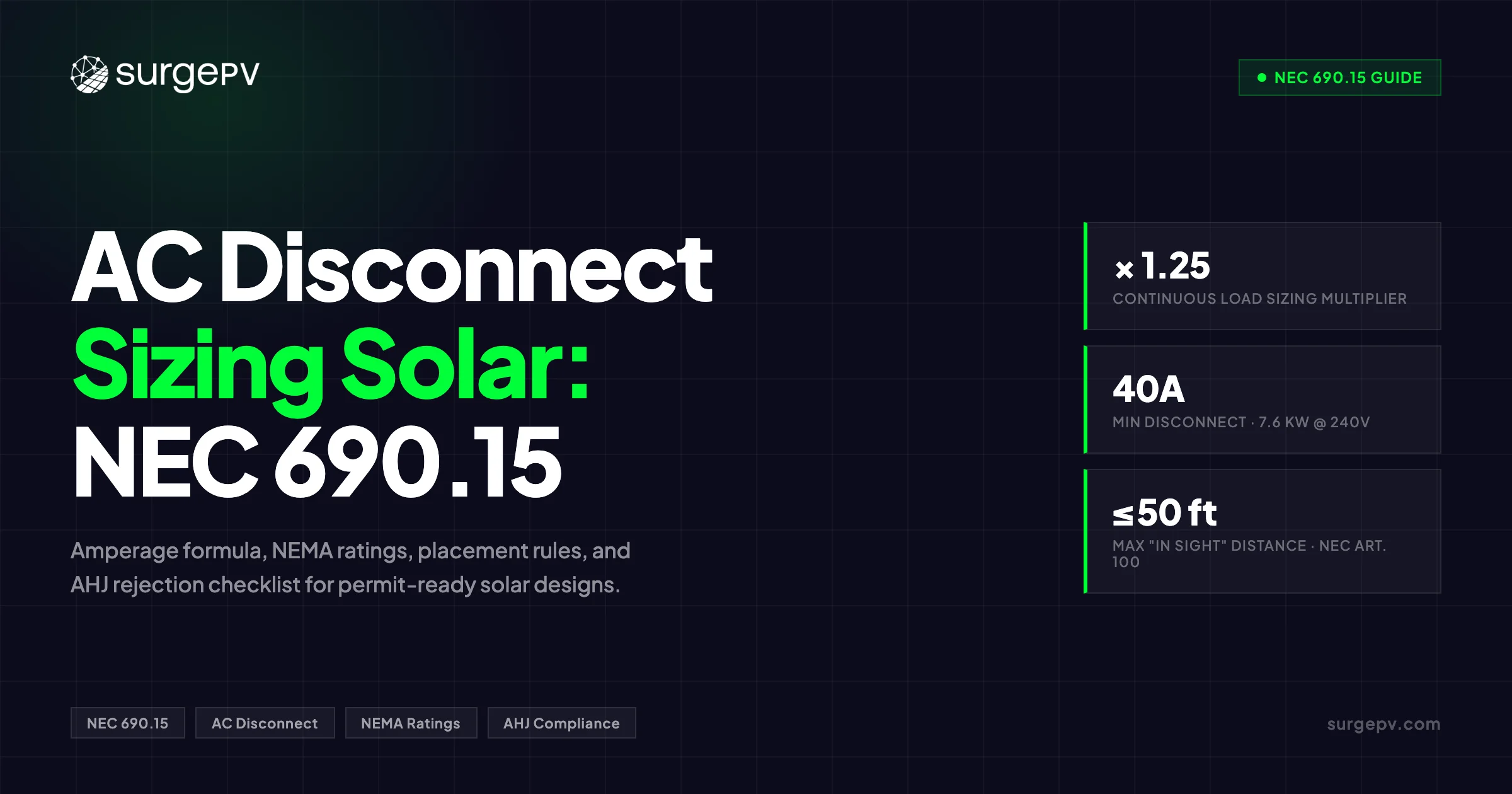
Minimum disconnect amperage = inverter max AC output current × 1.25. For a 7.6 kW inverter on 240V: 31.67A × 1.25 = 39.6A → 40A device. Minimum outdoor enclosure: NEMA 3R. The disconnect must be in sight of the inverter (visible, ≤50 ft) or lockable per NEC 110.25.
In this guide:
- Why NEC 690.15 and NEC 690.13 are different requirements that both apply to the same system
- The 1.25 sizing formula and the four steps to select the right device
- A complete worked example: 7.6 kW inverter, 240V, single-phase, with a 120% busbar rule check
- Fusible vs. non-fusible disconnects — which one the code requires for your configuration
- NEMA rating selection for outdoor, coastal, and industrial locations
- Utility-specific requirements beyond base NEC rules
- The 10 most common AHJ rejection reasons and how to fix them
What NEC 690.15 Actually Requires (and How It Differs From 690.13)
Confusing NEC 690.13 with NEC 690.15 is one of the more common mistakes on solar permit packages. They address different things, and both apply to the same system.
NEC 690.13 is the system-level shutoff. It requires a means to disconnect all ungrounded conductors of the PV system from all other wiring systems — one accessible switch that takes the entire PV array offline.
NEC 690.15 is equipment-level isolation. It requires a means to disconnect each individual piece of PV equipment — inverters, charge controllers, DC-to-DC converters, AC modules, and fuses — from all ungrounded conductors of all power sources that feed it. If equipment has more than one energy source, each source needs its own disconnect, and they must be grouped.
A main disconnect under 690.13 does not satisfy 690.15. Both apply simultaneously.
2023 NEC Restructuring
The 2023 NEC moved location rules for equipment disconnects from 690.15(A) to 690.15(D), and type/rating requirements from 690.15(D) to 690.15(A). If you reference older code commentary, the subsection numbers will be reversed. Check which edition your AHJ has adopted before citing code text.
The Four Compliance Options for Disconnect Location
Under NEC 690.15(D), equipment disconnects must comply with one of four options:
- Located within the equipment itself (integral disconnect)
- Located in sight from and readily accessible from the equipment
- Lockable in the open position per NEC 110.25, where the disconnect is not within sight
- Provided with remote controls — where the disconnect and controls are in the same equipment, or the disconnect is lockable per NEC 110.25 with the control location permanently labeled
“In sight from” has a specific NEC definition (Article 100): visible and not more than 50 feet distant. “Readily accessible” means reachable quickly without tools other than a key, without climbing over or under obstacles, and without a portable ladder.
| Requirement | NEC 690.13 | NEC 690.15 |
|---|---|---|
| Purpose | System-level shutoff — isolates entire PV system from building wiring | Equipment-level isolation for maintenance |
| Scope | All ungrounded PV conductors from other wiring systems | Individual components from all power sources |
| Location | Readily accessible; at outside or inside nearest point of entry | Within sight and readily accessible from equipment, or lockable |
| Satisfies the other? | No — both apply simultaneously | No — both apply simultaneously |
The practical implication: an inverter inside a utility room needs its own equipment disconnect at that location under 690.15, even if the main system disconnect under 690.13 is at the service panel across the building.
The AC Disconnect Sizing Formula
The minimum disconnect amperage rating is the inverter’s maximum continuous AC output current multiplied by 1.25.
Minimum disconnect rating = inverter max AC output current × 1.25The 1.25 factor is the continuous load multiplier. NEC Article 100 defines a continuous load as one that persists for three or more hours. Solar generation qualifies — on a clear day, peak production runs well past three hours. The factor keeps the disconnect from operating at 100% of its rated capacity during normal generation.
After applying 1.25, round up to the next standard device size. Never down.
Four steps:
- Find the inverter’s maximum continuous AC output current on the nameplate or specification sheet — not the peak or surge rating.
- Multiply by 1.25.
- Round up to the next standard size: 20A, 30A, 40A, 50A, 60A, 70A, 100A, 200A.
- Verify the device’s voltage rating meets or exceeds the system AC voltage: 120/240V for single-phase residential, 208/480V for three-phase commercial.
Pro Tip
Pull the maximum continuous AC output current from the inverter spec sheet — do not back-calculate from the power rating alone. For three-phase inverters especially, the per-phase current can differ from a simple P/V result once power factor and manufacturer derating are applied.
Worked Sizing Example: 7.6 kW Inverter, 240V Single-Phase
A 7.6 kW string inverter on a 240V single-phase service is the standard mid-size residential scenario — typically 18 to 22 panels depending on module wattage.
Given parameters:
- Inverter: 7,600 W
- AC voltage: 240V, single-phase
- Power factor: greater than 0.99 (modern string inverter)
Step 1 — Calculate maximum AC output current
I = P / V = 7,600W / 240V = 31.67AStep 2 — Apply 1.25 continuous load factor
31.67A × 1.25 = 39.58AStep 3 — Round up to next standard size
39.58A rounds up to 40A. That is the minimum compliant device for this inverter.
Step 4 — Wire pairing
A 40A disconnect requires minimum 8 AWG copper on the inverter-to-disconnect run (NEC Table 310.16, 90°C column). For runs longer than 50 feet, run the voltage-drop check and consider upsizing to 6 AWG. See the solar cable sizing calculation guide for the full derating procedure.
Step 5 — 120% busbar rule check (NEC 705.12)
For a 200A main panel with a 200A main breaker:
Maximum solar backfeed = (200A × 1.20) − 200A = 40AA 40A solar breaker lands exactly at the busbar limit. If the system needed a 50A disconnect, the options are: derate the main breaker to 175A, use a supply-side connection per NEC 705.12, or confirm the busbar’s independent rating exceeds the combined load.
Quick Reference: Residential Sizing
| System Size | Max AC Current (240V) | × 1.25 | Minimum Disconnect | Wire Gauge |
|---|---|---|---|---|
| 3 kW | 12.5A | 15.6A | 20A | 12 AWG |
| 5 kW | 20.8A | 26.0A | 30A | 10 AWG |
| 6 kW | 25.0A | 31.3A | 35A | 10 AWG |
| 7.6 kW | 31.7A | 39.6A | 40A | 8 AWG |
| 10 kW | 41.7A | 52.1A | 60A | 6 AWG |
| 12 kW | 50.0A | 62.5A | 70A | 4 AWG |
Wire gauges above are based on 90°C conductor ampacity at 30°C ambient with no conduit bundling. Apply temperature and conduit derating for actual site conditions.
Three-Phase Commercial Sizing
For a three-phase inverter: I = P / (√3 × V × PF). For a 30 kW inverter at 480V with PF = 1.0: I = 30,000 / (1.732 × 480) = 36.1A per phase. Minimum disconnect: 36.1 × 1.25 = 45.1A → 50A three-pole device.
Fusible vs. Non-Fusible Disconnects: Which One Does Your System Need?
Disconnect switches come in two types. Which one the code requires depends on what overcurrent protection already exists in the system.
Fusible disconnect switches combine fuses with a disconnect mechanism in one enclosure. They serve two purposes at once: isolate equipment for maintenance and provide overcurrent protection. This makes them the standard choice at DC combiner boxes, where they replace a separate combiner and a separate disconnect in a single unit.
Non-fusible disconnect switches provide isolation only. They have no overcurrent protection built in. Use them when a separately rated OCPD already exists upstream — a breaker in the main panel or a dedicated fuse block on the circuit.
The code logic is simple: NEC 690.9 requires overcurrent protection, and NEC 690.13–690.17 requires a disconnecting means. A fused disconnect covers both. A non-fused one requires a separate OCPD.
| Scenario | Required Device |
|---|---|
| No upstream OCPD present | Fusible disconnect (OCPD + isolation in one unit) |
| Upstream breaker or fuse block exists | Non-fusible disconnect acceptable |
| DC combiner box with multiple strings | Fusible disconnect typical |
| AC output between inverter and panel | Non-fusible acceptable (panel breaker is the OCPD) |
| Building entry point (NEC 690.13) | Either — depends on system architecture |
UL Listing Requirements
AC disconnects must be listed under UL 98 for the applicable AC voltage and amperage.
DC disconnects must be listed under UL 98B, which covers switches rated for DC applications up to 1000V DC, or 1500V DC for PV systems. An AC-rated UL 98 device must never be installed in a DC circuit. DC arcs do not self-extinguish at zero crossing the way AC arcs do — an AC-rated switch interrupting DC will sustain an arc and fail.
Never Substitute AC-Rated Switches in DC Circuits
DC current has no natural zero-crossing to extinguish arcs when a switch opens. An AC-rated switch interrupting DC current will sustain an arc and fail — often explosively. Verify the UL listing and the explicit DC voltage rating before installing any switch in a DC PV circuit.
For more on this topic, see DC Bus Voltage Optimization.
Placement Rules: Visibility, Height, and Working Clearance
Placement errors are the second most common AHJ rejection after wrong amperage. Three requirements govern where the disconnect lives.
”In Sight From” and “Readily Accessible”
NEC 690.15(D) requires the disconnect to be in sight from and readily accessible from the equipment it disconnects. In sight means visible and not more than 50 feet distant — both conditions must be met. A disconnect around a building corner that is less than 50 feet away but not visible does not comply.
Readily accessible means reachable without tools other than a key, without climbing over equipment or obstacles, and without a portable ladder. A disconnect mounted 8 feet up on a wall with no landing is not readily accessible.
Where the disconnect cannot be placed within sight, the alternative is lockable in the open position per NEC 110.25. The locking provision must be permanent — a padlock hasp that cannot be removed without tools.
Handle Height
NEC 404.8 sets the maximum mounting height at 6 feet 7 inches (2.0 m) to the center of the grip in its highest position. Most AHJs expect the operating handle between 4.5 and 6.5 feet above finished grade — the comfortable working range for most adults, consistent with ADA guidance for externally operable controls. Verify locally before finalizing. Read Solar Racking Design Guide for a complete walkthrough.
Working Clearance (NEC 110.26)
| Dimension | Minimum |
|---|---|
| Depth in front of panel | 36 inches |
| Width | 30 inches or equipment width (whichever is greater) |
| Headroom | 6 feet 6 inches |
| Illumination | Required at all working spaces |
Document the clearance on the elevation drawing. An inspector who cannot walk up to the disconnect without moving anything will flag it.
Pro Tip
Draw the 36-inch working clearance as a dashed box on the site plan and elevation. AHJ reviewers often ask for it explicitly. Putting it on the drawing eliminates one of the most predictable comment-cycle items.
NEMA Rating Selection for Your Environment
The enclosure must be rated for where it is installed. Using the wrong NEMA rating outdoors is the third most common plan-check rejection on AC disconnect submissions.
| NEMA Rating | Protection Level | Typical Solar Use |
|---|---|---|
| NEMA 1 | Indoor — basic dust and contact protection | Garage, utility room, climate-controlled space |
| NEMA 3R | Outdoor — rain-tight, sleet-resistant | Standard outdoor residential; pole-mounted disconnects |
| NEMA 4 | Outdoor/indoor — watertight, dust-tight | Industrial environments; wash-down areas |
| NEMA 4X | Outdoor/indoor — watertight, dust-tight, corrosion-resistant | Coastal installations; chemical exposure environments |
Outdoor minimum: NEMA 3R. A NEMA 1 enclosure outside is an immediate rejection.
Coastal: NEMA 4X. Many AHJs along the California coast, Florida, and the Gulf Coast require NEMA 4X within approximately 2 miles of saltwater. Salt-air corrosion will degrade a NEMA 3R metal enclosure within a few seasons at the coast. Fiberglass or 316 stainless steel NEMA 4X enclosures are the standard solution.
Sun exposure: Outdoor enclosures in direct sun experience significant internal temperature rise above ambient. Where direct sun exposure is unavoidable, use a shaded location, a sun shield, or enclosures with high-temperature-rated internal components. Shadow analysis software identifies shading issues before installation.
Coastal AHJ Verification
The “2 miles from saltwater” threshold for NEMA 4X is a common rule of thumb, not a universal code requirement. Some jurisdictions define the corrosive zone by prevailing wind patterns rather than distance. Confirm the local standard before specifying NEMA 3R on any coastal job.
Utility Interconnection Disconnect Requirements
Utility requirements go beyond the base NEC rules. Most utilities publish additional requirements in their interconnection agreements or technical standards.
NEC 705.20 Baseline
NEC 705.20 requires the disconnecting means for power production sources to be readily accessible and externally operable without exposing live parts. In practice, this means the AC disconnect must be reachable by utility workers without entering the building — grade level or exterior wall, not a locked mechanical room.
Lockability
Where the utility or AHJ requires it, the disconnect must be lockable in the open position per NEC 110.25. The locking provision must remain in place whether or not a lock is installed. A toggle switch with no padlock hasp does not satisfy this requirement.
Utility-Specific Rules
| Utility / Jurisdiction | Specific Requirement |
|---|---|
| Minnesota Power | Visible-open, lockable disconnect within 10 ft of utility meter |
| City of Columbia, MO | Solar disconnect within 6 ft and direct line of sight of meter base |
| LADWP (Los Angeles) | Visible-open safety disconnect required; type verified during inspection |
| Mesa, AZ | Lockable load-break disconnect with visible break; utility approval required prior to installation |
Pull the utility’s interconnection guide before finalizing placement. Utility rules can be stricter than NEC, and the code text alone will not reveal them.
Supply-Side vs. Load-Side: What Changes
For supply-side connections (NEC 705.12 supply-side tap), the interconnection disconnect sizing follows supply-side ampacity rules and the 120% busbar limitation does not apply. This changes the maximum allowable size of the interconnection breaker.
For load-side connections (backfed breaker), the 120% busbar rule limits the total solar breakers based on the panel’s main breaker and busbar rating. In load-side configurations, the AC disconnect and the backfed breaker are typically the same device.
Get Disconnect Sizing Right Before You Submit
SurgePV calculates the AC disconnect rating from your inverter spec automatically and includes it on the permit-ready single-line diagram — with the NEC code reference on the drawing.
Book a DemoNo commitment required · 20 minutes · Live project walkthrough
For a direct comparison, see Arka 360 vs SurgePV.
String Inverter vs. Microinverter: Disconnect Differences
The inverter architecture changes how the AC disconnect is configured — not whether one is required.
String Inverter Systems
String inverters convert DC at a central point. A typical residential system has one or two.
- Each inverter needs its own AC disconnect under NEC 690.15, or a single combined disconnect for the combined AC output.
- The DC disconnect between array and inverter input is also required; many string inverters include it as an integral switch.
- If the inverter is roof-mounted or not readily accessible, both the DC and AC disconnects must be within sight of or integral to the inverter per NEC 690.15(D).
Microinverter Systems
Microinverters convert DC to AC at each module. The DC side runs at low voltage (30–40V per module), which eliminates the high-voltage DC run across the roof.
- NEC 690.13(C) allows one AC disconnect for the combined output of all microinverters in an interactive system. The sizing rule still applies: total combined AC output current × 1.25.
- There is no high-voltage DC disconnect requirement — DC conductors from module to microinverter are at low voltage.
- Modern microinverter systems are inherently compliant with NEC 690.12 rapid shutdown — module-level shutdown is built in.
- The AC disconnect typically sits at an AC combiner panel or junction box where the microinverter branch circuits meet.
| Feature | String Inverter | Microinverter |
|---|---|---|
| AC disconnect count | 1 per inverter (or combined) | 1 for combined output |
| DC disconnect | Required between array and inverter | Minimal — module-level, low voltage |
| Rapid shutdown hardware | Additional hardware required | Built-in compliant |
| Disconnect location | Adjacent to inverter | At AC combiner junction |
| Panel-level monitoring | System-level only | Per module |
Multi-Inverter Systems: Single vs. Individual Disconnects
When a system has multiple string inverters, the NEC allows some flexibility — with conditions.
Single disconnect permitted: NEC 690.13(C) allows a single disconnecting means for the combined AC output of multiple inverters in an interactive system. The inverter collection subpanel approach uses this: each inverter feeds a dedicated subpanel via its own breaker, and one disconnect covers the entire subpanel output.
Individual disconnects required: If inverters are roof-mounted or not readily accessible, each one needs its own DC and AC disconnect within sight or integral to that inverter, regardless of whether a combined downstream disconnect also exists.
Maximum 6 switches per NEC 690.13(C): The PV system disconnect may consist of not more than 6 switches or 6 circuit breakers in a single enclosure or group of enclosures. Systems with more than 6 inverters use the subpanel approach to keep the final disconnect count within the limit.
Directory requirement: Where inverters are in multiple locations, NEC 705.10 requires a permanent plaque or directory at each service equipment location identifying where all power source disconnects are located. Some AHJs extend this requirement to every disconnect location in the system.
Why the Directory Matters for First Responders
The directory exists so emergency responders can find and operate every disconnect without searching the building. A firefighter who locates one switch but cannot find the others is in danger. The permanent directory at each location eliminates that uncertainty — and its absence is a rejection reason.
Common AHJ Rejection Reasons and How to Fix Them
Most disconnect rejections repeat the same errors. The table below lists the 10 most common, the NEC reference, and the fix.
| Rejection | NEC Reference | Fix |
|---|---|---|
| Disconnect undersized — wrong amperage | 690.15, 690.8 | Recalculate: inverter max AC current × 1.25, round up to standard size |
| Outdoor NEMA rating too low | 110.26, 690.15 | Minimum NEMA 3R outdoor; NEMA 4X coastal/industrial |
| No lock-on device — cannot be locked open | NEC 110.25 | Specify disconnect with padlock hasp; confirm in cut sheet |
| Not within sight, no lockout provision | 690.15(D) | Relocate within 50 ft visible, or specify lockable disconnect |
| Missing labels and placards | 690.13(B), 690.56 | Add permanent “PV SYSTEM DISCONNECT” label with voltage and current |
| Working clearance not on drawings | NEC 110.26 | Draw 36-in dashed envelope on site plan and elevation |
| OCPD rating mismatched from inverter spec | 690.8, 240 | Cross-check SLD against inverter cut sheet |
| Non-load-break switch where load-break required | 690.15(C) | Specify load-break rated disconnect for rooftop combiner locations |
| Missing directory for multi-location system | 705.10 | Install permanent plaque at each service equipment location |
| AC-rated switch in DC circuit | 690.15; UL 98B | Replace with UL 98B-listed DC-rated disconnect |
The Open-Position Warning Label
NEC 690.17(E) requires a specific warning sign wherever a disconnect’s terminals may remain energized in the open position. The exact text required by the code is:
WARNING: ELECTRIC SHOCK HAZARD. DO NOT TOUCH TERMINALS. TERMINALS ON BOTH THE LINE AND LOAD SIDES MAY BE ENERGIZED IN THE OPEN POSITION.
This label is mandatory at any disconnect where a second source can keep the load-side terminals live after the switch opens — for example, at the main service disconnect where PV backfeed may energize the load side even with the utility de-energized. Many plan sets omit it. Careful AHJ reviewers catch it every time.
Pro Tip
Add a labeling checklist to your permit package template: 690.13(B) system disconnect label, 690.56 placard, 690.17(E) open-position warning, and the 705.10 directory where the system spans multiple locations. Running through it before submission clears four of the ten rejection types above in one pass.
How Solar Design Software Gets Disconnect Sizing Right
Manual disconnect sizing on a residential permit set takes 5–10 minutes. On a commercial system with multiple inverters, three-phase configuration, and utility-specific requirements, it takes longer. Any step missed — wrong current source, forgotten 1.25 multiplier, wrong NEMA rating — produces a rejection.
Solar software handles this differently. After the inverter is selected from the equipment database, the software reads the rated maximum continuous AC output current from the spec sheet and applies the 1.25 multiplier. The result appears on the single-line diagram with the NEC code references — 690.15 and 690.8 — already on the drawing.
The SLD export from solar design software includes:
- Disconnect amperage and voltage rating labeled on the diagram
- NEMA rating flagged based on the installation environment set in project settings
- Lockability requirement noted where placement triggers NEC 110.25
- 690.17(E) warning label block pre-populated where applicable
- Wire gauge for the inverter-to-disconnect run, sized from the same 1.25 multiplier
The disconnect specifications on the permit set flow directly into the solar proposal software. The equipment the AHJ approves is the same equipment on the customer proposal and the bill of materials.
For multi-inverter commercial systems, SurgePV applies the six-device limit from NEC 690.13(C) automatically and flags configurations that would exceed it. The subpanel consolidation approach is offered as an option when the inverter count hits the limit.
AHJ Plan Review Speed
Permit sets with pre-calculated disconnect ratings and code references on the SLD move through plan review faster. The reviewer does not re-derive the calculation — it is already on the drawing. That difference is what separates a first-pass approval from a correction cycle.
Conclusion
Three things drive most AC disconnect rejections:
- Wrong amperage: Sizing to the inverter’s power rating instead of its rated continuous output current, and skipping the 1.25 multiplier.
- Wrong enclosure: Using NEMA 1 or NEMA 3R where NEMA 4X is required, or failing to document the NEMA rating on the plan set.
- Wrong placement: Exceeding 50 feet or line of sight from the inverter without providing a lockable disconnect.
The formula is not complex: inverter max AC output current × 1.25, rounded up to the next standard device. The placement rule is clear: in sight (visible, ≤50 ft) and readily accessible, or lockable. The NEMA rule has two tiers: NEMA 3R for standard outdoor, NEMA 4X for coastal and corrosive environments.
Get those three right and you clear the majority of disconnect rejections before the permit set leaves your desk. Solar design software that runs the calculation automatically removes the manual step and puts the code reference on the drawing where the AHJ needs to see it.
Frequently Asked Questions
What size disconnect do I need for a 7.6 kW solar inverter?
A 7.6 kW inverter on a 240V single-phase circuit draws 31.67A at full output. Apply the 1.25 continuous load factor: 31.67A × 1.25 = 39.6A. Round up to 40A — the next standard device size. Pair it with minimum 8 AWG copper for the inverter-to-disconnect run. If the system connects to a 200A main panel with a 200A main breaker, the 120% busbar rule allows exactly 40A of solar backfeed — 200A × 1.20 − 200A = 40A.
Can I use a circuit breaker as an AC disconnect for solar?
Yes. A circuit breaker listed as suitable for use as a disconnecting means satisfies NEC 690.13 and NEC 705.12, provided it is rated for the correct voltage and amperage (inverter max AC output current × 1.25) and can be locked in the open position where required. A standard residential breaker with no locking provision does not satisfy a utility’s lockability requirement without adding a lockable handle or a separate disconnect.
How far can an AC disconnect be from the inverter?
Under NEC 690.15(D), the disconnect must be in sight from the inverter — visible and not more than 50 feet distant — and readily accessible. Where it cannot be placed within sight, it must be lockable per NEC 110.25. Some utilities add stricter distance requirements, such as 6 or 10 feet from the meter base. Verify with the local AHJ and utility before finalizing the layout.
What NEMA rating is required for an outdoor solar AC disconnect?
NEMA 3R is the minimum for standard outdoor locations. In coastal areas (typically within 2 miles of saltwater, though the exact threshold varies by AHJ) or locations with corrosive atmospheres, upgrade to NEMA 4X. NEMA 4X adds watertight and corrosion-resistant construction — fiberglass or 316 stainless steel — that holds up where NEMA 3R metal enclosures degrade within a few seasons.
Do microinverter systems still need an AC disconnect?
Yes. NEC 690.13(C) allows one AC disconnect for the combined output of all microinverters in an interactive system, but it still requires one. Size it using total combined AC output current × 1.25. Placement, NEMA rating, and labeling requirements are the same as any other AC disconnect. The simplification is that one device covers the entire array output — no individual disconnects per module.
Build Permit-Ready Designs With AC Disconnect Sizing Included
SurgePV selects the correct disconnect rating from the inverter spec and puts it on the SLD with the NEC code reference — ready for AHJ review.
Start DesigningNo commitment required · Works for residential and commercial systems