Quick Answer
The 40% limit leaves 60% of the conduit's internal space as clearance to allow thermal dissipation and to prevent conductor damage during pulling. Pulling 12 conductors through a conduit packed to 50% fill risks cutting insulation at bends. NEC Chapter 9 Table 1 Note 4 allows up to 60% fill for conduit nipples — sections 24 inches or shorter connecting two boxes or enclosures.
Conduit fill is a top cause of AHJ inspection failures on residential and commercial solar installations. Get it wrong and you face a re-pull, rescheduled inspection, and a delay that can cost $200–$500 or more in labor before the permit closes. Get it right the first time and commissioning stays on schedule.
The 40% limit leaves 60% of the conduit’s internal space as clearance to allow thermal dissipation and to prevent conductor damage during pulling. Pulling 12 conductors through a conduit packed to 50% fill risks cutting insulation at bends.
This guide walks through the full NEC Chapter 9 calculation method: the three fill-percentage rules, the three tables every solar electrician needs, a step-by-step worked example for a typical residential string system, and a ready-to-use reference table for common solar conduit sizes. It also covers temperature derating interaction and the eight mistakes that most often trigger inspector callbacks. For more on this topic, see Temperature Derating Solar Conductors.
TL;DR — Conduit Fill for Solar PV
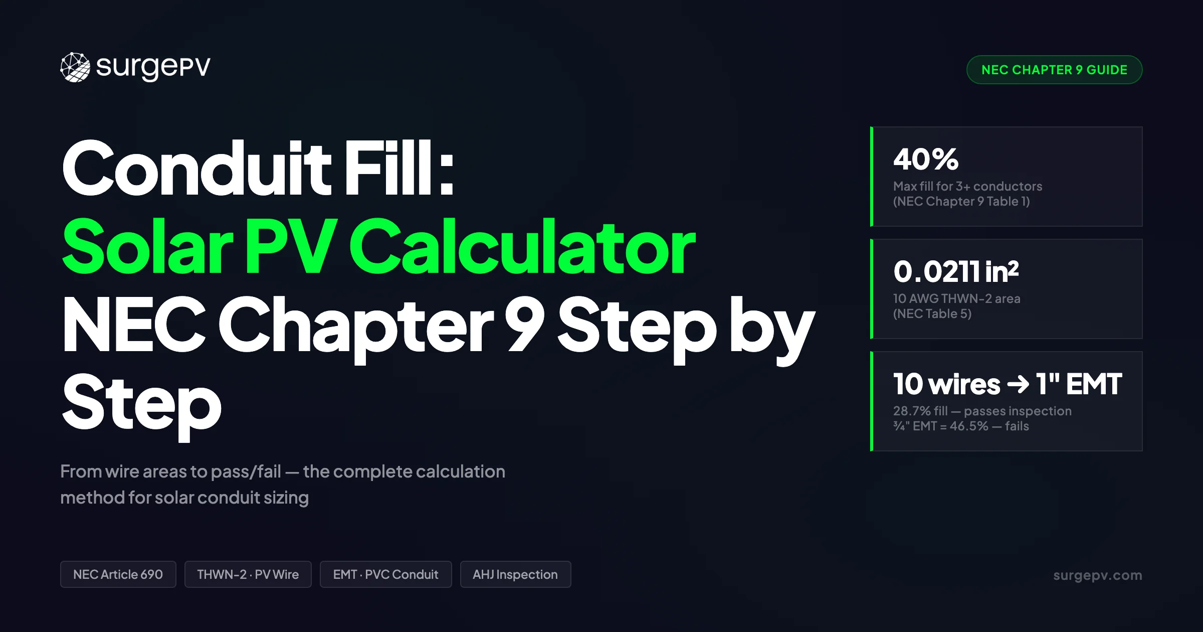
NEC Chapter 9 Table 1 sets the limits: 53% for 1 conductor, 31% for 2, 40% for 3 or more. Find each conductor’s cross-sectional area in Table 5, find the conduit’s internal area in Table 4, divide, and compare. A 1-inch EMT carrying 10× 10 AWG THWN-2 plus one 8 AWG EGC hits 28.7% fill — well under the 40% limit. PV Wire is significantly larger than THWN-2 at the same AWG, so always use the correct row from Table 5.
In this guide:
- NEC Chapter 9 Table 1 fill limits and why they exist
- The three NEC tables you need for every calculation
- EMT vs. PVC Schedule 40 vs. PVC Schedule 80 vs. RMC — conduit selection for solar
- Wire types: THWN-2, XHHW-2, and PV Wire — cross-sectional areas and common errors
- Step-by-step worked example: residential 5-string homerun
- Temperature derating interaction (NEC 310.15(C)(1))
- Eight common mistakes that cause AHJ callbacks
- Ready-to-use conduit fill reference table
How NEC Chapter 9 Conduit Fill Rules Work
NEC Chapter 9 contains the wiring method and conductor installation tables that govern conduit fill. Table 1 sets the maximum percentage of a conduit’s internal cross-sectional area that conductors can occupy — measured as the ratio of total conductor area (including insulation) to conduit internal area.
The three tiers in Table 1:
| Number of Conductors | Max Fill (% of Internal Area) |
|---|---|
| 1 | 53% |
| 2 | 31% |
| 3 or more | 40% |
| Nipple (≤24 inches) | 60% |
The 40% limit for 3 or more conductors governs nearly every solar conduit run, since most homeruns carry at least 2 positive, 2 negative, and a ground.
Why these limits exist. Heat is the primary driver. Conductors generate heat under load, and conduit traps it. Excessive fill reduces airflow between conductors and raises operating temperature, which accelerates insulation degradation and — in extreme cases — creates fire risk. The 40% limit leaves 60% of the conduit’s internal space as clearance to allow thermal dissipation and to prevent conductor damage during pulling.
A secondary reason is mechanical. Pulling 12 conductors through a conduit packed to 50% fill risks cutting insulation at bends. The fill limits are calibrated to keep pulling tension manageable.
The nipple exception. NEC Chapter 9 Table 1 Note 4 allows up to 60% fill for conduit nipples — sections 24 inches or shorter connecting two boxes or enclosures. Solar installers use this for short stub-ups through roof penetrations and short transitions between junction boxes.
What counts toward fill. Every conductor, including the equipment grounding conductor (EGC). The EGC gets a derating exemption for ampacity (NEC 310.15(E)(1)), but it does not get a fill exemption — its cross-sectional area always counts toward the total.
The Three NEC Tables You Need
Every conduit fill calculation requires exactly three tables from NEC Chapter 9. Keep these bookmarked.
Table 1 — Maximum Fill Percentages
The fill-limit table above. Use it in the final step of every calculation to confirm you are under the limit.
Table 4 — Conduit and Tubing Dimensions
Table 4 lists the internal cross-sectional area (in²) for every conduit type and trade size. These are the denominator in your fill calculation.
Key values for solar conduit runs:
| Trade Size | EMT (in²) | PVC Sch 40 (in²) | PVC Sch 80 (in²) | RMC (in²) |
|---|---|---|---|---|
| ½” | 0.304 | 0.285 | 0.217 | 0.289 |
| ¾” | 0.533 | 0.508 | 0.409 | 0.508 |
| 1” | 0.864 | 0.832 | 0.688 | 0.814 |
| 1¼” | 1.496 | 1.453 | 1.237 | 1.453 |
| 1½” | 2.036 | 1.986 | 1.711 | 1.986 |
| 2” | 3.356 | 3.291 | 2.874 | 3.291 |
PVC Schedule 80 has substantially smaller internal area than Schedule 40 at the same trade size. A 1-inch Sch 80 holds 17.5% less area than 1-inch Sch 40.
Table 5 — Conductor Cross-Sectional Areas
Table 5 lists the total cross-sectional area of each conductor type and size, including insulation. These are the numerators.
Key values for solar wiring:
| AWG | THWN-2 (in²) | XHHW-2 (in²) | PV Wire (in²) |
|---|---|---|---|
| 14 | 0.0097 | 0.0109 | 0.0167 |
| 12 | 0.0133 | 0.0152 | 0.0206 |
| 10 | 0.0211 | 0.0243 | 0.0333 |
| 8 | 0.0366 | 0.0437 | 0.0437 |
| 6 | 0.0507 | 0.0590 | 0.0726 |
| 4 | 0.0824 | 0.0940 | — |
| 2 | 0.1333 | 0.1515 | — |
| 1/0 | 0.1855 | 0.2223 | — |
Critical note on PV Wire. PV Wire at 10 AWG is 0.0333 in² — 58% larger than 10 AWG THWN-2 (0.0211 in²). XHHW-2 is also larger than THWN-2 at the same AWG (10 AWG XHHW-2 = 0.0243 in², about 15% larger). If you run either wire type inside conduit, use the correct column — not the THWN-2 values. Using THWN-2 values for XHHW-2 or PV Wire will undercount fill and can produce a conduit that looks compliant on paper but fails inspection when the AHJ measures actual conductor diameters.
Annex C — Pre-Calculated Wire Counts
Annex C provides pre-calculated maximum conductor counts by conduit type, size, and wire type. It works as a quick sanity check. However, Annex C covers THWN/THHN wire only. It does not apply to PV Wire or USE-2. For mixed-type or PV Wire runs, use Tables 4 and 5 directly.
Conduit Types for Solar PV: EMT, PVC, and RMC
Choosing the right conduit type affects how many conductors fit at the same trade size, which determines whether you need to upsize.
EMT (Electrical Metallic Tubing)
EMT has the largest internal area of any common conduit type at the same trade size. It is the conduit of choice for indoor and protected outdoor runs — inverter rooms, conduit in garages, runs along interior walls.
NEC 358.10 restricts EMT from locations subject to severe physical damage and from direct burial unless listed for that use. On rooftops, EMT is acceptable where it runs on a surface that provides adequate support and protection.
PVC Schedule 40
PVC Sch 40 is the workhorse for outdoor solar conduit: rooftop surface runs exposed to weather, underground runs from the array to the combiner box, stub-ups through roof penetrations. Its internal area is slightly smaller than EMT (1-inch PVC Sch 40 = 0.832 in² vs. EMT = 0.864 in²), but the difference is minor.
PVC is UV-resistant in its listed form, does not corrode, and is compatible with direct burial and concrete encasement per NEC 352.10. Use gray electrical PVC — white plumbing PVC is not listed for electrical use.
PVC Schedule 80
Schedule 80 has thicker walls than Schedule 40, which means smaller internal area at the same trade size. Use it where mechanical protection is required: runs exposed to physical damage risk (vehicle traffic areas, exposed floor penetrations, runs within 6 feet of grade on external walls).
At 1-inch trade size, Sch 80 holds approximately 17% less internal area than Sch 40 (0.688 in² vs. 0.832 in²). If your Sch 40 calculation comes out near the 40% limit, switching to Sch 80 of the same size may push you over — you may need to upsize to 1¼”.
RMC (Rigid Metal Conduit)
RMC is the thickest, heaviest, and most expensive option. Its internal area is similar to EMT but its wall thickness offers greater mechanical protection. Solar applications are limited to commercial or industrial sites with high physical damage risk. For most residential installations, RMC is not warranted.
| Conduit Type | Internal Area (1”) | Best Solar Use |
|---|---|---|
| EMT | 0.864 in² | Indoor, protected outdoor, inverter room |
| PVC Sch 40 | 0.832 in² | Outdoor, underground, rooftop exposed runs |
| PVC Sch 80 | 0.688 in² | Exposed runs where physical damage is possible |
| RMC | 0.814 in² | Commercial/industrial, high-damage-risk areas |
Wire Types in Solar PV Systems
3 wire types dominate solar conduit runs. Each has a different cross-sectional area even at the same AWG.
THWN-2
THWN-2 is the most common wire for conduit runs in solar systems — from combiner box or junction box to inverter, from inverter to AC panel. It is rated 90°C in dry and wet locations. The “-2” suffix confirms the wet-location 90°C rating, which NEC 690.31 requires for solar circuits.
XHHW-2
XHHW-2 uses cross-linked polyethylene (XLPE) insulation. Its cross-sectional area is about 15% larger than THWN-2 at the same AWG (10 AWG XHHW-2 = 0.0243 in² vs. 0.0211 in² for THWN-2), so it takes up more conduit space for the same circuit. Its advantage is better heat resistance and flexibility in cold temperatures — useful for rooftop pulls in winter climates. Always use the XHHW-2 column from Table 5 when calculating fill, not the THWN-2 column.
PV Wire
PV Wire (UL 4703) and USE-2 wire are designed for DC source circuits — string runs from panels to combiner box or DC disconnect. PV Wire’s thicker insulation makes it significantly larger in cross-section at the same AWG. As noted above, 10 AWG PV Wire is 58% larger than 10 AWG THWN-2.
When PV Wire is run in conduit (required when it leaves the array boundary in most jurisdictions), use PV Wire’s actual Table 5 values. Mixing PV Wire and THWN-2 in the same conduit is allowed, but you must sum each conductor’s actual area from the correct row.
Pro Tip
Transition from PV Wire to THWN-2 at a junction box before the homerun conduit when possible. THWN-2’s smaller cross-section means you can use a smaller conduit trade size for the same number of circuits — or fit more strings in the same conduit.
Step-by-Step Conduit Fill Calculation: Worked Example
Scenario: A residential 5-string system, all strings on 10 AWG THWN-2, running a homerun from combiner box to string inverter in 1-inch EMT.
- 5 strings × 2 conductors (positive + negative) = 10 current-carrying conductors, 10 AWG THWN-2
- 1 equipment grounding conductor (EGC), 8 AWG THWN-2
- Conduit: 1-inch EMT
Step 1 — List All Conductors
| Conductor | Count | AWG | Type |
|---|---|---|---|
| DC positive | 5 | 10 | THWN-2 |
| DC negative | 5 | 10 | THWN-2 |
| EGC | 1 | 8 | THWN-2 |
| Total conductors | 11 |
Step 2 — Find Each Conductor’s Area (NEC Table 5)
- 10 AWG THWN-2: 0.0211 in²
- 8 AWG THWN-2: 0.0366 in²
Step 3 — Sum Total Conductor Area
| Conductor Group | Calculation | Area (in²) |
|---|---|---|
| 10× 10 AWG THWN-2 | 10 × 0.0211 | 0.2110 |
| 1× 8 AWG THWN-2 (EGC) | 1 × 0.0366 | 0.0366 |
| Total | 0.2476 |
Step 4 — Find Conduit Internal Area (NEC Table 4)
- 1-inch EMT internal cross-sectional area: 0.864 in²
Step 5 — Calculate Fill Percentage
Fill % = Total conductor area ÷ Conduit internal area × 100
Fill % = 0.2476 ÷ 0.864 × 100 = 28.7%
Step 6 — Compare to NEC Table 1 Limit
11 conductors fall in the “3 or more” category → maximum fill = 40%
28.7% ≤ 40% ✓ — conduit is properly sized.
Verification: Would ¾-inch EMT pass?
¾-inch EMT internal area = 0.533 in²
Fill % = 0.2476 ÷ 0.533 × 100 = 46.5% — exceeds 40% ✗ — fails inspection.
1-inch EMT is the correct minimum for this run.
Worked Example Summary
11 conductors (10× 10 AWG THWN-2 + 1× 8 AWG THWN-2 EGC) in 1-inch EMT = 28.7% fill. Limit is 40%. Minimum conduit is 1-inch EMT. Dropping to ¾-inch EMT pushes fill to 46.5% and fails inspection.
Temperature Derating and Conduit Fill: The Interaction You Cannot Ignore
Conduit fill percentage and ampacity derating are separate calculations — but they interact in ways that can force you to upsize wire even when conduit fill passes.
NEC 310.15(C)(1) — More Than 3 Current-Carrying Conductors
When a conduit carries more than 3 current-carrying conductors, the ampacity of each conductor must be derated. The adjustment factors from NEC 310.15(C)(1):
| Current-Carrying Conductors | Ampacity Adjustment |
|---|---|
| 4–6 | 80% |
| 7–9 | 70% |
| 10–20 | 50% |
| 21–30 | 45% |
| 31–40 | 40% |
| 41+ | 35% |
The EGC does not count as a current-carrying conductor for derating purposes — the adjustment factors in NEC 310.15(C)(1) apply only to current-carrying conductors. However, the EGC still counts for fill calculations.
In the worked example above, 10 current-carrying conductors trigger the 50% derating factor.
- 10 AWG THWN-2 base ampacity at 90°C: 40A (NEC 310.16)
- 50% derating: 40A × 0.50 = 20A allowable ampacity
- This is fine for 7A string current — but always verify your actual string Isc before assuming compliance
Rooftop Temperature Adder (NEC 2023 310.15(B)(2))
Conduit mounted above a rooftop receives an ambient temperature correction. Under NEC 2023 Section 310.15(B)(2), a single adder of +33°C (60°F) applies to conductors in raceways installed within 7/8 inch of the roof surface. For raceways installed higher than 7/8 inch above the roof, no adder applies under the 2023 code.
Most surface-mounted rooftop conduit sits within 7/8 inch of the roof. If your design ambient is 30°C, the effective conduit ambient becomes 63°C — which drops the conductor’s temperature correction factor significantly below 1.0. XHHW-2 wire handles this better than THWN-2 in high-temperature rooftop runs because of its superior heat resistance.
These 2 derating factors (conductor count + rooftop temperature) stack multiplicatively. Always run both before finalizing wire sizing, even if your fill percentage is well under 40%. Read Solar Cable Sizing Calculation for a complete walkthrough.
Design Order Matters
Calculate wire sizing (ampacity + derating) first. Then check conduit fill. If derating forces you to upsize from 10 AWG to 8 AWG, the larger wire changes your fill percentage and may require a larger conduit — which changes fill again. Run wire size first, conduit size second.
Common Conduit Fill Mistakes on Solar Installations
These are the 8 errors that generate AHJ callbacks most often on solar conduit inspections.
1. Skipping the EGC in fill. Some installers know the EGC does not derate current-carrying capacity and incorrectly assume it also does not count toward fill. It does. Always include it.
2. Using THWN-2 areas for PV Wire. At 10 AWG, this underestimates area by 58%. Running PV Wire in conduit using THWN-2 Table 5 values is one of the most frequent solar-specific fill errors.
3. Forgetting the neutral on AC combiner runs. Microinverter systems and AC module systems route individual 120V or 240V circuits back to an AC combiner. These circuits include a neutral, which is an additional conductor that counts toward fill.
4. Assuming Annex C applies universally. Annex C tables are based on THWN/THHN wire. They do not apply to PV Wire, USE-2, or conductors with non-standard insulation profiles. Using Annex C for PV Wire will undercount required conduit size.
5. Substituting PVC Schedule 80 where Schedule 40 was calculated. If you designed for Sch 40 internal area (0.832 in² for 1-inch) but field-installed Sch 80 (0.686 in² for 1-inch), fill jumped from the designed percentage to a higher number — potentially over 40%.
6. Not rechecking fill after upsizing wire for derating. If temperature derating requires upsizing from 10 AWG to 8 AWG, re-run the fill calc with 8 AWG areas. 8 AWG THWN-2 (0.0366 in²) is 73% larger than 10 AWG (0.0211 in²). The same conduit that passed at 28.7% may now fail.
7. Applying the nipple exception to runs over 24 inches. The 60% fill exception applies only to conduit nipples 24 inches or shorter. A 30-inch stub-up is not a nipple — it must meet the standard 40% limit.
8. Mixing wire sizes without summing each separately. If a homerun carries 10 AWG strings and a 6 AWG feeder, look up each AWG and type individually in Table 5 and sum them. Do not estimate.
AHJ Inspection Tip
Bring a completed fill calculation sheet to every rough-in inspection. Most inspectors will accept a printed or phone-based calculation showing the Table 1, 4, and 5 values used. It turns a visual check into a documented pass and reduces re-inspection risk.
Automate Your Solar Electrical Calculations
SurgePV’s solar design software handles conduit sizing, string calculations, and one-line diagrams — so your design packages are inspection-ready before you reach the job site.
Book a DemoNo commitment required · 20 minutes · Live project walkthrough
For a direct comparison, see Arka 360 vs SurgePV.
Quick Reference: Conduit Fill Table for Solar PV
This table gives the maximum number of 10 AWG THWN-2 conductors allowed in common solar conduit sizes at the 40% fill limit. For other wire sizes, use: (Conduit internal area × 0.40) ÷ conductor area = max conductors.
| Trade Size | EMT (in²) | Max 10 AWG THWN-2 | PVC Sch 40 (in²) | Max 10 AWG THWN-2 | PVC Sch 80 (in²) | Max 10 AWG THWN-2 |
|---|---|---|---|---|---|---|
| ½” | 0.304 | 5 | 0.285 | 5 | 0.217 | 4 |
| ¾” | 0.533 | 10 | 0.508 | 9 | 0.409 | 7 |
| 1” | 0.864 | 16 | 0.832 | 15 | 0.688 | 13 |
| 1¼” | 1.496 | 28 | 1.453 | 27 | 1.237 | 23 |
| 1½” | 2.036 | 38 | 1.986 | 37 | 1.711 | 32 |
| 2” | 3.356 | 63 | 3.291 | 62 | 2.874 | 54 |
Max conductors calculated as floor((internal area × 0.40) ÷ 0.0211). These are theoretical maximums — actual installations must also account for derating, pulling tension, and EGC sizing.
For solar design software, these calculations happen automatically as part of your design package. A good solar software platform integrates conduit sizing into the one-line diagram output so you catch fill violations before the permit set goes to the AHJ.
What Gets Flagged at AHJ Inspections
Conduit fill violations are among the most-cited NEC deficiencies on solar rough-in inspections. Here is what inspectors check most often.
Overfilled conduit. The most common citation. An inspector who sees a conduit visibly packed with conductors will measure or count. Even marginally over 40% is a red mark and requires a re-pull or a new, larger conduit.
Wrong conduit type for the location. EMT installed underground without concrete encasement or listed burial fittings violates NEC 358.10. PVC conduit that is not UV-listed (white plumbing PVC vs. gray electrical PVC) fails. Inspectors in coastal markets also check for corrosion resistance.
Unsecured conduit. EMT must be supported within 3 feet of each box, conduit body, or fitting, and at intervals not exceeding 10 feet (NEC 358.30). PVC Schedule 40 requires support within 3 feet of each box and at intervals not exceeding 3 feet for trade sizes ½” through 1”, or 5 feet for 1¼” and larger (NEC 352.30). A conduit that sags between supports is a citation even if fill is correct.
Missing or undersized EGC. Inspectors verify that an equipment grounding conductor of the correct size (per NEC 250.122) is present in every conduit containing circuit conductors. Missing EGC is an automatic fail.
Conduit damage at bends. Overfilled conduit during installation often shows flattening or kinking at bends — evidence that pulling tension was too high. Inspectors can require a re-pull if bend damage is visible.
For any design that goes to permit, use solar proposal software that generates a complete electrical package including a one-line diagram with conduit sizing. That documentation speeds inspector review and reduces back-and-forth.
Conduit fill ties directly to your NEC Article 690 compliance documentation. See the NEC Article 690 glossary for the full scope of requirements that apply to PV source and output circuits. If you are tracking changes in the upcoming code cycle, the NEC 2026 solar changes post covers what is changing in the next edition.
Conclusion
Conduit fill calculations for solar PV are not complicated — but they require using the right tables in the right order. 3 things to do on every job:
- Use Table 5 for the wire type actually installed. PV Wire and THWN-2 are not interchangeable for fill purposes. Pull the correct row for each conductor in the conduit.
- Run derating before confirming conduit size. If derating forces a wire upsize, re-run fill with the new conductor areas. The 2 calculations interact.
- Document your fill calculation before the rough-in inspection. A printed or digital calc sheet showing Tables 1, 4, and 5 values turns a subjective visual check into a documented pass.
For complex commercial systems — multiple combiners, mixed wire sizes, long runs with multiple conduit types — use solar design software that integrates conduit sizing into the design output. Manual calculations for a 50-circuit commercial array are time-consuming and error-prone.
Frequently Asked Questions
How do I calculate conduit fill for solar PV?
Use NEC Chapter 9: sum the cross-sectional areas of all conductors (from Table 5), divide by the conduit’s internal area (from Table 4), and confirm the result is below the Table 1 limit — 53% for 1 conductor, 31% for 2, and 40% for 3 or more. For a 1-inch EMT carrying 10× 10 AWG THWN-2 plus one 8 AWG EGC, total fill is 28.7% — comfortably under the 40% limit.
How many 10 AWG wires fit in 1-inch EMT conduit?
NEC Annex C lists a maximum of 16 conductors of 10 AWG THWN-2 in 1-inch EMT at the 40% fill limit. In practice, a residential solar homerun of 10 current-carrying conductors plus one 8 AWG EGC sits at roughly 29% fill. If you add a neutral for a split-phase AC run, recalculate with the actual conductor count and areas.
Does the equipment grounding conductor count toward conduit fill?
Yes. Per NEC Chapter 9 Table 1 Note 3, equipment grounding conductors are included in the fill calculation. The EGC derating exemption (NEC 310.15(E)(1)) applies only to ampacity derating — not to the physical fill percentage. Always include the EGC cross-sectional area when calculating conduit fill.
What is the NEC fill limit for 3 or more conductors in conduit?
40% of the conduit’s total internal cross-sectional area. This applies when 3 or more conductors share a conduit, per NEC Chapter 9 Table 1. The limit drops to 31% for exactly 2 conductors and rises to 53% for a single conductor. An exception allows up to 60% fill for conduit nipples that are 24 inches or shorter.
Can I use PVC conduit for outdoor solar wiring?
Yes — PVC Schedule 40 is the standard choice for outdoor and underground solar conduit runs. It is UV-resistant, corrosion-proof, and listed for direct burial and concrete encasement. PVC Schedule 80 has thicker walls and smaller internal area than Schedule 40 at the same trade size, so it holds fewer conductors. EMT should not be used underground unless it has listed fittings for that application.