

A single loose ground connection can turn a commissioning day into a rework day. It can also create a shock hazard that outlasts the installation warranty. That is why a solar continuity test is not a checkbox exercise. It is the proof that every protective path in a PV system will carry fault current safely if something goes wrong.
IEC 62446-1:2016, the international commissioning standard for grid-connected PV systems, lists continuity of protective earthing and equipotential bonding conductors as the first Category 1 test. In practice, many installers still use a basic multimeter beep to sign off earthing. That is usually the wrong instrument for the job. This guide explains when to use a milliohm meter, when a multimeter is enough, what pass thresholds to record, and how to document results so the system can be commissioned without delay.
Quick Answer
A solar continuity test verifies that protective earthing, equipotential bonding, and DC string conductors form complete, low-resistance paths before energization. IEC 62446-1 mandates the test for all grid-connected PV systems. Use a low-resistance ohmmeter for protective conductors and record readings against local thresholds, typically less than 1 Ω.
In this guide:
- What a solar continuity test actually measures
- Why the right instrument matters — milliohm meter vs multimeter
- The standards that require continuity testing
- Step-by-step procedures for protective earthing and string continuity
- Pass thresholds and how to interpret them
- Common failures and how to troubleshoot them
- How design documentation makes field testing faster
- FAQ
What Is a Solar Continuity Test?
A continuity test checks that an electrical path is unbroken between two points. In a solar PV system, that path matters for two different reasons: safety and energy production.
Protective earthing and bonding continuity confirms that module frames, mounting rails, inverter enclosures, and any other exposed conductive parts are connected to the main earthing terminal. If a live conductor touches a frame, the fault current has a low-resistance route to earth that will trip a protective device quickly.
String and circuit continuity confirms that the DC conductors running from the modules through the combiner box to the inverter are electrically continuous. A break anywhere in the string will stop production or, worse, create an arc fault.
The two tests use different instruments and different thresholds. Confusing them is the most common mistake on site. Protective earthing needs a measured resistance value, often in milliohms. String continuity is usually verified by voltage and current measurements because a PV string is itself a power source.
Why Continuity Testing Matters
Continuity is invisible. A module frame can look securely bolted to a rail while an anodized coating or a paint layer blocks the electrical bond. A connector can feel fully seated while the pin barely touches the socket. The faults only appear when you measure them.
Hypothetical example: A 250 kW rooftop system is commissioned in Arizona. The crew uses a standard multimeter continuity beep to check every frame bond. The meter beeps on all 40 strings, so the test sheet is signed. Two months later, a ground-fault alarm trips. A thermal camera shows one string of frames is floating at 380 V relative to earth because the rail bond was reading 28 Ω, not the expected milliohms. The beep passed, but the bond did not protect anyone.
The purpose of a protective earthing continuity test is to guarantee that fault current is high enough to operate the overcurrent device or residual current detector within the time required by the local code. A bond of 28 Ω on a 240 V system limits fault current to about 8.5 A. Many circuit breakers will not trip on that. A bond under 0.1 Ω pushes fault current above 2,000 A, which clears a fault in milliseconds.
Continuity records also protect the installer. Warranty claims, insurance disputes, and utility interconnection sign-offs increasingly require documented commissioning test results. A sheet stamped with pass/fail ticks is weaker than a sheet with measured resistance values, instrument serial numbers, and ambient conditions.
Standards That Require Solar Continuity Testing in 2026
Continuity testing is not optional in any major solar market. The exact threshold and method vary, but the requirement is universal.
IEC 62446-1:2016
IEC 62446-1:2016 defines the commissioning tests for grid-connected PV systems. Its Category 1 test regime, which applies to every grid-connected system, begins with continuity of protective earthing and equipotential bonding conductors. The standard also covers polarity, string voltage, string current, insulation resistance, and functional tests.
Category 2 adds I-V curve tracing and infrared thermography for larger or more complex systems. Neither category removes the continuity requirement.
NEC Article 250 and Article 690
In the United States, NEC 2023 Article 250 requires equipment grounding conductors to be continuous and low impedance. Article 690 contains PV-specific grounding and bonding rules. Local Authorities Having Jurisdiction often require measured continuity values on inspection checklists.
BS 7671 and UK Grid Codes
In the United Kingdom, BS 7671:2018 requires continuity of protective conductors as part of initial verification. The measured R1+R2 value is used to calculate earth fault loop impedance, Zs. MCS installation standards also require continuity results on the commissioning certificate.
IEEE 1547-2018
While IEEE 1547-2018 is primarily an interconnection standard, it reinforces the need for safe grounding and bonding as a precondition for grid connection. Utility interconnection agreements often require IEC 62446-1 or equivalent commissioning records.
Test Instruments: Milliohm Meters vs Multimeters
The instrument you choose determines what the result actually means.
Digital Multimeter Continuity Mode
A digital multimeter in continuity mode applies a small test voltage and sounds a tone when the resistance between the probes drops below a threshold. Fluke notes that on a 400 Ω range, a typical multimeter beeps when the measured resistance is about 40 Ω or less.
That is perfectly fine for checking whether a fuse is blown, whether a switch closes, or whether a cable has a break. It is not fine for proving that a protective earth bond can clear a fault. A 35 Ω bond will beep happily while remaining dangerous.
Multimeters also measure in a two-wire configuration. The reading includes the resistance of the test leads and the contact resistance between the probe and the metal surface. On a low-resistance bond, lead resistance can be larger than the bond itself.
Low-Resistance Ohmmeter / Milliohm Meter
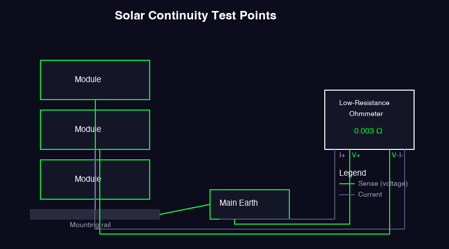
A low-resistance ohmmeter, sometimes called a DLRO or micro-ohmmeter, uses a four-wire Kelvin connection. It passes a known current through the path with one pair of leads and measures the voltage drop with a second pair. Tektronix explains that this eliminates the voltage drop in the test leads, so the reading is the resistance of the joint itself.
Megger DLRO models commonly resolve down to 0.1 µΩ or 1 µΩ and can measure bonds under 1 Ω with accuracy of ±0.25%. They are the correct tool for commissioning-grade protective earthing continuity.
| Feature | Multimeter Continuity Mode | Low-Resistance Ohmmeter |
|---|---|---|
| Typical beep/pass threshold | Up to 40 Ω | User-defined, often under 1 Ω |
| Lead resistance included? | Yes | No, with four-wire Kelvin leads |
| Resolution | 0.1 Ω to 1 Ω typical | 1 µΩ to 1 mΩ typical |
| Best use | Go/no-go troubleshooting | Compliance documentation |
| Cost | Low | Moderate to high |
The practical rule is simple: use a multimeter for quick checks on de-energized circuits and a low-resistance ohmmeter for protective earthing bonds that must be documented.
How to Perform a Protective Earthing Continuity Test
Protective earthing continuity is a dead test. The system must not be energized. Follow the test sequence in IEC 62446-1, which runs AC circuit tests first, then DC-side tests.
Step 1: Prepare the Installation
- Confirm the inverter AC breaker is open.
- Confirm the DC isolators are open and strings are disconnected.
- Verify all modules and frames are exposed conductive parts that require bonding.
- Clean test points of paint, anodizing, dirt, and oxidation. A star washer or a bare metal scrape is often needed.
Step 2: Select Reference Points
The reference point is the main earthing terminal, usually at the distribution board or inverter enclosure. Every test is measured from this point to the component being tested.
Typical test points include:
- Module frame at each string
- Mounting rail at each row
- Inverter enclosure
- Combiner box enclosure
- Cable tray or conduit
- Any accessible metallic enclosure in the DC circuit
Step 3: Measure with a Four-Wire Instrument
Connect the current leads of the low-resistance ohmmeter on either side of the bond path. Connect the sense leads as close as possible to the points being measured. Press the test button and record the value.
For long runs, such as from the main earthing terminal to a remote array frame, the reading includes the protective conductor run. That is expected, but the total must still meet the local threshold.
Step 4: Compare Against the Pass Threshold
IEC 62446-1 Annex A gives an informative pass value of less than 1 Ω between any earthed component and the main earthing terminal. Many regulators and EPC specifications tighten this:
- Frame-to-rail bonds: under 0.1 Ω
- Equipotential bonding: under 0.05 Ω
- Main earth run: under 1 Ω
Always use the strictest value that applies to the project: local code, utility requirements, or the EPC contract.
Step 5: Document the Result
Record the test point, measured value, ambient temperature, instrument serial number, calibration date, and pass/fail verdict. A photo of the test lead placement is useful for warranty or dispute resolution.
How to Perform a String Continuity Test
String continuity means the positive and negative conductors from the modules to the inverter are complete. Because a PV module produces voltage whenever light hits it, you cannot simply put a multimeter in ohmmeter mode across an exposed string. The module will back-feed the meter.
Method 1: Voltage Verification
The standard commissioning approach is to measure Voc and Isc at the string terminals and compare them to calculated expected values. If the string is open somewhere, Voc will read close to zero or will be missing a module’s contribution. If a connector is badly seated, the string may show Voc but fail to deliver Isc.
Expected Voc at test temperature = module Voc × number of modules × [1 + (T_module − 25) × Temp_coeff_Voc]
A measured Voc within ±3% of the expected value confirms the series path is continuous. A measured Isc within ±5% confirms the current path is intact. These checks are covered in more detail in our solar system commissioning protocol.
Method 2: Isolated Resistance Check
If the string can be fully shaded or disconnected at every module, you can use a multimeter resistance check to confirm the cable path has no break. This is rarely practical on a rooftop but can be useful in a factory or ground-mount setting where strings are assembled on the ground before lifting.
Set the multimeter to the lowest resistance range. Connect one lead to the positive conductor at the combiner end and one to the positive conductor at the module end. A reading near zero confirms continuity. Repeat for the negative conductor. Do not use this method on an illuminated string.
Worked Example: Interpreting a Continuity Reading
A 10 kW residential system in Florida uses 25 modules mounted on two rows of aluminum rail. The commissioning engineer tests five frame-to-rail bonds with a low-resistance ohmmeter and records the following values:
| Test Point | Measured Resistance | Verdict | Interpretation |
|---|---|---|---|
| Module 1 frame to rail A | 0.003 Ω | Pass | Excellent metal-to-metal bond |
| Module 13 frame to rail A | 0.004 Ω | Pass | Consistent with neighboring bonds |
| Module 25 frame to rail B | 0.280 Ω | Marginal | Anodized coating likely present |
| Rail A to rail B splice | 0.002 Ω | Pass | Low-resistance splice |
| Rail B to inverter enclosure | 0.950 Ω | Pass (but investigate) | Long earth run or loose lug |
The 0.280 Ω reading on module 25 is the warning sign. It is still below the 1 Ω IEC threshold, but it is 70 times higher than the bonds on the same rail. The installer removes the lug, finds an anodized rail surface, scrapes it clean, adds a star washer, and retests. The new reading is 0.004 Ω.
The 0.950 Ω reading from rail B to the inverter enclosure also passes, but it is close enough to the limit that the engineer checks the entire earth run. The lug at the inverter was slightly loose. After torqueing it to the manufacturer’s specification, the reading drops to 0.120 Ω.
This example shows why a pass/fail sheet would hide the real story. The two marginal readings were early warnings of bonds that would likely fail within a few years due to corrosion or vibration. Recording actual values lets the crew fix problems while the scaffolding is still up.
Pass Thresholds and Interpretation
The right threshold depends on what you are testing and which standard governs the project.
| Test Point | Typical Acceptance | Standard Reference |
|---|---|---|
| Protective earthing any component to MET | Less than 1 Ω | IEC 62446-1 Annex A |
| Frame bond to rail | Less than 0.1 Ω | Common EPC specification |
| Equipotential bonding | Less than 0.05 Ω | BS 7671 best practice |
| String Voc deviation | Within ±3% of calculated | IEC 62446-1 / project spec |
| String Isc deviation | Within ±5% of calculated | IEC 62446-1 / project spec |
A reading that is close to but below the threshold should be investigated. A 0.95 Ω earth bond on a residential system may technically pass IEC 62446-1, but it is close enough to the limit that corrosion or a loose clamp could push it over the line within a year. The best installers aim for values an order of magnitude below the maximum.
Common Mistakes and Troubleshooting
Even with the right instrument, continuity tests can give misleading results. These are the failures we see most often in the field.
Testing on an Energized Circuit
A low-resistance ohmmeter injects current to measure resistance. If the circuit is live, the meter can be damaged and the user can be shocked. Always isolate the circuit first.
Dirty or Painted Contact Points
Anodized aluminum rail, painted steel conduit, or oxidized copper can add ohms of contact resistance. Scrape or use a bonded test point. A star washer under the lug is often the difference between a pass and a fail.
Relying on the Multimeter Beep Alone
As noted earlier, a beep only proves the resistance is below the meter’s threshold. It does not prove the bond is safe. Record the actual value.
Forgetting Lead Calibration
Test leads and probes have their own resistance. High-quality instruments have a zero or null function. Use it every time the lead set changes.
Not Checking All Bond Paths
A module frame may be bonded to a rail, but the rail may not be bonded to the next rail or to the main earth. Test every segment of the path, including the hard-to-reach ones.
High Resistance at MC4 Connectors
A partially seated MC4 pin can add resistance in the current path without being visually obvious. If string Isc is low but Voc is correct, suspect a connector or a crimp.
Continuity Testing in Design and Documentation
Good commissioning starts in design. The single-line diagram should show every intended earth point, bond jumper, and test location. If the drawing does not show it, the crew may not install it, and the tester may not check it.
Modern solar design software can export a bill of materials that includes grounding hardware, lug counts, and conductor lengths. That prevents the common scenario where a crew runs out of grounding washers halfway through the array and improvises.
For projects that need PE-stamped permit drawings or detailed engineering deliverables, a solar design and engineering consultancy can prepare the test-point documentation and single-line diagrams before construction starts. This reduces both rework and commissioning-day surprises.
Documentation should travel with the project. The commissioning report should include:
- A marked-up single-line diagram showing test points
- A table of measured continuity values
- Instrument calibration certificates
- Ambient temperature and weather conditions
- Photos of any corrected defects
For client handover, PV proposal software can package these records into a professional commissioning report that supports warranty and insurance claims.
Design Systems That Pass Tests the First Time
SurgePV helps you specify grounding, string sizing, and test points during design — so your commissioning day is a sign-off day, not a rework day.
Book a DemoNo commitment required · 20 minutes · Live project walkthrough
Real-World Tradeoffs: When to Test Every Point and When to Sample
On a 5 kW residential system with 12 modules, testing every frame bond takes 15 minutes. On a 50 MW plant with 150,000 modules, testing every bond is impossible. The question is not whether to test, but how to sample.
For residential and small commercial systems, test every protective earthing bond. The time cost is low and the liability risk is high.
For utility-scale plants, test a representative sample of bonds per block or per table. Increase the sample rate in areas with known corrosion risk, such as coastal or industrial sites. Document the sampling plan in the commissioning procedure so it can be defended to the owner, insurer, and lender.
The same tradeoff applies to string continuity. Residential systems should have Voc and Isc measured for every string. Large commercial systems may sample a percentage of strings per inverter, as long as any deviation triggers a full retest of the affected zone.
Conclusion and Next Steps
A solar continuity test is the proof that a PV system is safe before it is turned on. It is also the data that protects the installer, owner, and financier for the life of the project.
The key takeaways:
- Use a low-resistance ohmmeter for protective earthing and bonding, not a multimeter beep.
- Record measured values rather than pass/fail ticks alone.
- Verify string continuity through Voc and Isc measurements, not resistance checks on live strings.
- Clean contact points and use four-wire Kelvin leads for accurate results.
- Include test points and grounding details in the design package.
Three actions for your next project:
- Update your commissioning checklist. Replace any multimeter-based earthing continuity step with a low-resistance ohmmeter procedure and a documented threshold.
- Review your design deliverables. Confirm the single-line diagram shows every intended earth point and bond path. Use solar design software to catch missing grounding hardware before procurement.
- Train the crew on contact preparation. A 30-second scrape with a star washer can prevent a failed test and a return visit.
For a complete commissioning walkthrough, see our solar panel installation guide and solar commissioning checklist.
Frequently Asked Questions
What is a solar continuity test?
A solar continuity test checks that protective earthing conductors, equipotential bonding, and DC string conductors form complete, low-resistance paths. It is a mandatory Category 1 commissioning test under IEC 62446-1 for all grid-connected PV systems.
What instrument should I use for a solar continuity test?
Use a low-resistance ohmmeter or milliohm meter with four-wire Kelvin leads for protective earthing and bonding. A standard digital multimeter in continuity mode is acceptable only for basic go/no-go checks on de-energized wiring, not for compliance documentation.
What is the acceptable continuity reading for a solar installation?
IEC 62446-1 Annex A typically accepts less than 1 Ω between any earthed metallic component and the main earthing terminal. Many installers and regulators aim for under 0.1 Ω for frame bonds and under 0.05 Ω for equipotential bonding.
How do you test string continuity on a solar PV system?
Because PV strings are energized by light, true continuity is checked indirectly by measuring open-circuit voltage and short-circuit current against expected values. With the string fully isolated and shaded, a multimeter resistance check can confirm the conductor path has no open circuit.
Can you use a multimeter for solar continuity testing?
Yes, for quick troubleshooting, but not for commissioning-grade protective earthing tests. Most multimeter continuity modes beep at resistances up to 40 Ω on a 400 Ω range, which is too coarse to verify a safe fault-current path.
What standards require solar continuity testing?
IEC 62446-1:2016 lists continuity of protective earthing and equipotential bonding as the first Category 1 test. In the United States, NEC Article 250 governs equipment grounding conductor continuity. In the UK, BS 7671 requires continuity of protective conductors.
How often should solar continuity tests be repeated?
Continuity of protective conductors is tested at initial commissioning and should be rechecked after any structural modification, lightning strike, or ground-fault event. Periodic inspections under IEC 62446-3 typically repeat earthing continuity every 1 to 2 years.
What are the most common continuity test failures in solar systems?
Common failures include anodized aluminum rail coatings blocking frame bonds, loose or corroded grounding lugs, missing star washers, MC4 connector pins not fully seated, and test leads with poor contact adding false resistance.
Where this fits
This article is part of SurgePV's Solar Installation hub, which works through the topic from first principles to the decisions a project team actually has to make.

