Grid voltage at your point of connection is climbing. Every new solar array on the feeder pushes power back, and the cables, transformers, and tap changers between you and the substation get squeezed. By 2024, more than 12 percent of German low-voltage feeders had logged over-voltage events tied to PV feed-in (Fraunhofer ISE, 2024). The fix is not bigger cables. It is reactive power compensation from the inverter itself. See our guide on Community Solar Projects Germany for more. Read Community Solar Business Model for a complete walkthrough.
This guide explains how solar inverters provide reactive power, what cos(phi) and Q(U) modes actually do, and which settings your grid operator will demand in 2026. It is written for installers, EPCs, and asset owners who design systems that must pass commissioning on the first attempt.
Quick Answer
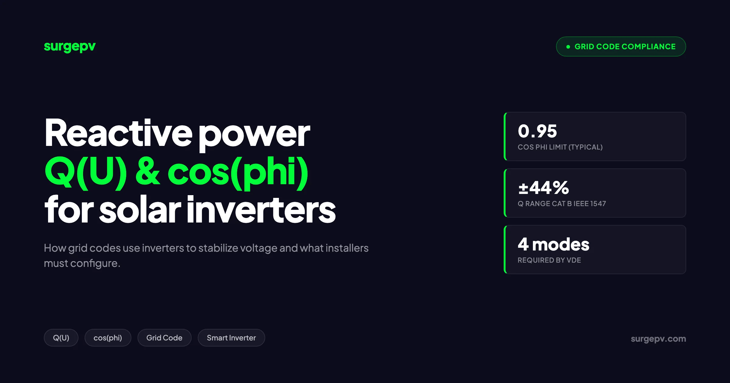
Reactive power compensation is the inverter’s ability to inject or absorb VARs to keep voltage in band. Modern grid codes require it on every system above 3.68 kVA in the EU and on every Category B install in the US. The two main modes are cos(phi) (fixed or P-dependent) and Q(U) (voltage-dependent Volt-VAR). Set them per the DNO’s letter or fail commissioning.
In this guide
- How active, reactive, and apparent power form the P-Q-S triangle
- The physics behind why solar inverters can deliver VARs without batteries
- cos(phi) fixed, cos(phi)(P), Q(U), and Q(P) modes compared
- Country grid codes: VDE-AR-N 4105 (Germany), IEEE 1547-2018 (US), CEI 0-21 (Italy), G99 (UK), AS/NZS 4777.2 (Australia)
- Configuration walk-throughs for SMA, Huawei, and Sungrow inverters
- Cost of oversizing the inverter to keep active yield
- The five mistakes that cause the most DNO penalties Also see: solar panel ROI in Italy. Also see: Germany solar subsidies.
Why grids need reactive power from solar inverters in 2026
Answer first
Distribution grids were designed for one-way flow. Solar pushes power backwards through the same conductors, raising voltage at the customer end. Reactive power compensation lets the inverter pull voltage back down without curtailing real watts.
The European low-voltage grid runs at 230 V phase to neutral. The legal band is 230 V plus 10 percent and minus 15 percent (EN 50160). A typical 8 kWp residential array on a long rural feeder can lift the connection point voltage by 2 to 3 percent under full sun (Fraunhofer ISE, 2024). Stack three or four neighbours together and the band breaks. Also see: European Solar Incentives. For Europe-specific compliance details, see Europe solar compliance.
The classical fix was to upsize the cable or add a new transformer tap. Both take 12 to 36 months and cost the DNO real money. Reactive power compensation does the same job in software, today, on hardware the customer already paid for.
Germany was first to demand it in 2011 with VDE-AR-N 4105. The US followed with IEEE 1547-2018, which is now baseline in California, Hawaii, New York, and most ISO territories (NREL, 2024). Italy moved in 2014 with CEI 0-21. The UK rolled G99 in 2019. Every new utility-scale project in 2026 will ship with reactive power modes enabled out of the gate. Read more about Battery Solar System Design UK. Read more about Commercial Rooftop Solar Case Study Italy.
The shift matters for installers because the default factory setting on most inverters is still cos(phi) = 1 (no VARs). If you ship that to a German rooftop above 3.68 kVA, the DNO will reject the commissioning report and you will pay for a second visit.
For installers and EPCs, the solar design software you use should publish the inverter’s reactive power capability curve as part of the proposal, not buried in a datasheet appendix. We built Surge to do that automatically.
P, Q, S triangle: defining real, reactive, apparent power
Answer first
Active power (P, in kW) does work. Reactive power (Q, in kVAr) shifts the phase between voltage and current and supports voltage. Apparent power (S, in kVA) is the vector sum: S squared equals P squared plus Q squared. The inverter is rated in kVA, so Q and P share the same budget.
In a pure resistive load, voltage and current move in lockstep. Power is the simple product V times I, and every joule of energy delivered does work. In a load with inductance (motors, transformers) or capacitance (long cables, capacitor banks), current leads or lags voltage by a phase angle phi. The cosine of that angle is the power factor.
The triangle works like this:
| Quantity | Symbol | Unit | What it does |
|---|---|---|---|
| Active (real) power | P | kW | Heats the kettle, spins the motor shaft |
| Reactive power | Q | kVAr | Builds the magnetic and electric fields, supports voltage |
| Apparent power | S | kVA | Total volt-amperes the inverter must deliver |
| Power factor | cos(phi) | unitless | P divided by S, between -1 and +1 |
A 10 kVA inverter set to cos(phi) = 0.90 delivers a maximum of 9 kW active and 4.36 kVAr reactive at the same time. Push it harder and the IGBT switches overheat, the firmware curtails, and your customer gets a yield warning. See our glossary of active and reactive power for the formal definitions.
The convention for sign matters. In Europe, positive Q means the inverter is over-excited (acts like a capacitor, injects VARs, lifts voltage). Negative Q means under-excited (acts like an inductor, absorbs VARs, lowers voltage). The US IEEE 1547-2018 convention is the opposite. Many commissioning errors come from this single sign flip.
How solar inverters provide reactive power
Answer first
A grid-tied inverter is a four-quadrant voltage-source converter. Its PWM controller can shift the output current waveform ahead of or behind the grid voltage waveform. Reactive power needs no extra hardware, just firmware and a kVA budget. The DC bus does not supply it. Reactive power circulates inside the converter.
For more on this topic, see DC Bus Voltage Optimization.
A modern string inverter uses IGBT or SiC switches running at 16 to 32 kHz. The controller compares the measured grid voltage waveform with a reference current waveform. By advancing or retarding the reference, the controller chooses the phase angle between V and I. That angle sets cos(phi).
This is the key insight that confuses many installers. The DC side of the inverter (your panels) does not provide reactive power. Reactive energy oscillates four times per cycle between the grid inductance and the inverter’s DC link capacitor. The MPPT tracker only sees active power flow. Your panels do not work harder when you set cos(phi) to 0.90.
What does work harder is the inverter itself. Higher current at the same voltage means more I-squared-R loss in the switches, the chokes, and the AC filter. Datasheet curves from SMA and Huawei show 0.3 to 0.8 percent extra heat dissipation at cos(phi) = 0.90 versus cos(phi) = 1.0 (SMA Sunny Tripower technical info, 2024).
The inverter can also provide reactive power at night, when DC voltage is zero. The technique is called Q at night or STATCOM mode. The DC link capacitor stays charged from the grid through the freewheel diodes, and the switches modulate just enough current to inject VARs. SMA’s Q on Demand 24/7 is the best-known implementation (SMA, 2024). Sungrow and Huawei offer similar functions on three-phase commercial units. Residential inverters rarely support it.
Pro Tip
If the DNO demands Q at night for a rooftop above 250 kWp, confirm the inverter model supports it before you order. Retrofitting requires hardware swap, not firmware update. SMA Sunny Tripower CORE2, Huawei SUN2000-MA, and Sungrow SG-CX support it. Many cheaper brands do not.
cos(phi) fixed mode explained
Answer first
Fixed cos(phi) is the simplest reactive power mode. The inverter holds one power factor value at all output levels. It is used on small rooftop systems where the DNO does not need dynamic response. Common values are 0.95 under-excited, 0.95 over-excited, or 1.00.
In fixed cos(phi) mode, you program a single number into the inverter. The inverter then delivers reactive power in fixed proportion to active power, regardless of grid voltage. If P is 5 kW and cos(phi) is set to 0.95 over-excited, Q is 5 times tan(arccos(0.95)) = 1.64 kVAr.
The mode is cheap to compute and cheap to commission. The DNO measures cos(phi) once at the meter, checks the value matches the connection agreement, and signs off.
The weakness is that fixed cos(phi) reacts only to active power. It does nothing when grid voltage rises because a neighbour switches off a load. In a dense PV neighbourhood, fixed cos(phi) is too coarse. That is why every grid code added Q(U) on top of it.
Use fixed cos(phi) when:
- The system is below the DNO’s threshold for Q(U) (3.68 to 13.8 kVA in Germany)
- The feeder has low PV density and no measured over-voltage history
- The grid operator’s standard letter specifies a single cos(phi) value
- You want to minimise commissioning complexity
In Germany, the standard offering for residential rooftop is cos(phi) = 0.95 under-excited above 3.68 kVA and below 13.8 kVA. Above 13.8 kVA, expect a cos(phi)(P) curve or Q(U). See the grid code glossary entry for regional variations.
cos(phi)(P) variable mode explained
Answer first
cos(phi)(P) is a piecewise function where the power factor depends on the active power output. Below 50 percent of nameplate, cos(phi) is usually 1.0 (no VARs). Above 50 percent, it ramps linearly toward 0.95 or 0.90. This protects small loads from unnecessary VAR flow.
The German standard cos(phi)(P) curve has four breakpoints:
| Active power (% Pn) | cos(phi) | Notes |
|---|---|---|
| 0 | 1.00 | No reactive power below threshold |
| 50 | 1.00 | Start of ramp |
| 100 | 0.95 under-excited | Full reactive at full output |
| Over 100 | 0.95 under-excited | Cap at nameplate Q |
The shape protects neighbouring loads. At low solar output (morning, evening, cloudy), the inverter does not push extra current through the feeder cables. At high output, when voltage rise is largest, the inverter pulls hardest on cos(phi).
The mode is the workhorse for German rooftop systems between 13.8 kVA and 100 kVA (VDE-AR-N 4105, 2018). Italy uses a similar curve under CEI 0-21 with slightly different breakpoints. Most major brands ship the curve as a one-line file you load through the installer interface.
The disadvantage is the same as fixed cos(phi): the curve reacts to your own output, not to actual grid voltage. If your system is the only PV on a strong feeder, you push VARs that do nothing useful and pay 1 to 2 percent in extra losses. If you are one of 30 systems on a weak feeder, the curve may not be enough.
For 100 kVA and above, solar proposal software should let you model both cos(phi)(P) and Q(U) so you can show the customer the yield difference before commissioning.
Q(U) Volt-VAR curve explained
Answer first
Q(U) is a four-point voltage-to-reactive-power curve. The inverter measures grid voltage at its terminals and looks up Q from the curve. When voltage rises above the dead band, the inverter absorbs Q (acts inductive). When voltage sags, the inverter injects Q (acts capacitive). It is the most effective mode for high-PV feeders.
The standard Q(U) curve looks like a sideways Z with a flat middle. The four voltage breakpoints (V1, V2, V3, V4) and the four reactive power points (Q1, Q2, Q3, Q4) are set by the DNO. IEEE 1547-2018 Category B default settings, published by JCP&L in November 2023:
| Point | Voltage (p.u.) | Reactive power |
|---|---|---|
| V1 | 0.92 | +44 percent (inject) |
| V2 | 0.98 | 0 |
| V3 | 1.02 | 0 |
| V4 | 1.08 | -44 percent (absorb) |
The dead band V2 to V3 is critical. Inside this band, the inverter does nothing. Outside it, the inverter ramps Q linearly. The slope between V3 and V4 determines how aggressively the inverter pulls voltage down.
The dead band design prevents hunting. If the slope is too steep and the dead band too narrow, two inverters on the same feeder can oscillate against each other, swinging voltage up and down every few seconds. Most DNOs publish their default curve in a settings letter that you load into the inverter unchanged.
Response time matters. IEEE 1547-2018 requires Category B inverters to reach 90 percent of the new Q setpoint within 5 seconds. VDE-AR-N 4105 sets the time at 10 seconds by default, configurable from 6 to 60 seconds (VDE, 2018). Faster is not always better. On feeders with tap-changing transformers, a 10 second response avoids fighting the tap changer.
Model Q(U) impact before commissioning
Surge calculates voltage rise, Q(U) response, and resulting yield loss in one pass. Avoid surprise DNO rejections.
Book a DemoNo commitment required · 20 minutes · Live project walkthrough
Country grid codes: a 2026 comparison
Answer first
Germany, the US, Italy, the UK, and Australia all mandate inverter reactive power, but with different thresholds, default modes, and response times. The table below is the 2026 working baseline. Always check the DNO letter for the specific project.
For Australia-specific compliance details, see Australia comparisons/lgc-vs-stc.
Germany — VDE-AR-N 4105
The reference standard for low-voltage PV in Europe. Reactive power is required above 3.68 kVA. Storage default is cos(phi) = 1, configurable. Q(U) was added in the 2018 revision and is now the preferred mode above 13.8 kVA. Response time default is 10 seconds (VDE, 2018).
For systems above 100 kVA, the medium-voltage standard VDE-AR-N 4110 applies. It demands continuous cos(phi) between 0.90 over-excited and 0.90 under-excited, plus Q at night for plants above 1 MVA.
United States — IEEE 1547-2018
Replaces IEEE 1547-2003 nationwide. Adoption is rolling state by state, led by California (Rule 21, 2017), Hawaii, New York, and the PJM and CAISO ISOs (NREL, 2024). Inverter-based DERs default to Category B with Volt-VAR enabled and constant power factor disabled.
Default Vref is typically 1.02 p.u. with the dead band 0.98 to 1.02 (JCP&L, 2023). Each utility publishes its own letter. The certification path is UL 1741 Supplement B (SB).
Italy — CEI 0-21
Applies to all generators connected to low voltage. Reactive power required above 11.08 kVA. The cos(phi)(P) curve runs from 1.00 at 20 percent output to 0.90 over-excited at 100 percent. Q(U) is optional and rarely demanded for residential. The standard underwent revision in 2022 (CEI, 2022).
United Kingdom — Engineering Recommendation G99
Applies to all generators above 16 A per phase (Type A, B, C, D). G99 demands an operating envelope of 0.95 leading to 0.95 lagging. The default mode in DNO standard arrangements is fixed cos(phi) = 1, with the DNO free to specify another value. G98 covers single-phase below 16 A and does not require active reactive power control.
Australia — AS/NZS 4777.2:2020
Applies to all inverters up to 200 kVA. Four pre-loaded regional curves: Australia A, Australia B, Australia C, and New Zealand. Each curve specifies cos(phi)(P), Q(U), and volt-watt response. The default for most states is Australia A, which includes cos(phi) = 0.90 over-excited at full output and a Q(U) dead band of 0.97 to 1.03 p.u. (Standards Australia, 2020).
For installers crossing borders, the grid export limitation rules article tracks the same five jurisdictions for the export limit side of compliance.
| Country | Standard | Threshold | Default mode | Response time |
|---|---|---|---|---|
| Germany | VDE-AR-N 4105 | 3.68 kVA | cos(phi)(P) or Q(U) | 10 s |
| United States | IEEE 1547-2018 | All inverter DER | Q(U), Cat B | 5 s |
| Italy | CEI 0-21 | 11.08 kVA | cos(phi)(P) | 10 s |
| United Kingdom | G99 | 16 A per phase | Fixed cos(phi) | 30 s |
| Australia | AS/NZS 4777.2 | All grid-connect | Pre-loaded region curve | 10 s |
Setting up reactive power on real inverter platforms
Answer first
Every major inverter brand exposes reactive power modes through the installer login. SMA uses Sunny Portal or SMA 360. Huawei uses FusionSolar app and SmartLogger. Sungrow uses iSolarCloud. The terms differ but the underlying settings are the same.
SMA Sunny Tripower (commercial three-phase)
Open the installer login on the inverter web interface (default 192.168.1.1 over the inverter wifi hotspot). Navigate to “Device parameters” then “Grid management services” then “Reactive power”.
The modes available are:
- Q, direct setpoint in kVAr (used by central plant controllers)
- cos phi, fixed value
- cos phi(P), with up to 10 breakpoints
- Q(U), with up to 10 breakpoints
For VDE-AR-N 4105 compliance, load the German country profile during commissioning, then verify the cos(phi)(P) breakpoints match the DNO letter. SMA ships standard country profiles that pre-load 90 percent of the compliance configuration (SMA service manual, 2024).
To enable Q at night, set “Q on Demand 24/7” to “Active”. Note that this mode is mutually exclusive with cos(phi) modes between day and night transitions. Choose one or the other.
Huawei SUN2000
Use FusionSolar installer app over Bluetooth or wifi. Navigate to “Settings” then “Power adjustment” then “Reactive power control”.
Modes available are:
- No output (cos phi = 1)
- Power factor (fixed cos phi)
- Reactive power compensation Q/S
- Power factor with active power, cos(phi)(P)
- Q-U characteristic curve
- Q-U hysteresis curve
The Q(U) hysteresis variant adds a delay between voltage entering and exiting the dead band, useful on feeders with frequent transient events. Huawei publishes country-specific profiles for Germany, Italy, Spain, UK, and Australia in the FusionSolar app library (Huawei SUN2000 user manual, 2024). Also see: Spain net metering.
Sungrow SG-CX and SG-RT
Connect via iSolarCloud installer login or local LAN to the inverter. Navigate to “Advanced settings” then “Grid parameters” then “Reactive power”.
Modes available are:
- Off (no reactive power)
- PF (fixed cos phi)
- Qt (fixed Q in kVAr)
- Q(P) (Q as function of active power)
- Q(U) (Volt-VAR with 4 to 10 points)
- PF(P) (cos phi as function of active power)
Sungrow includes Q at night on SG-CX models above 110 kW (Sungrow product brochure, 2024). The enable flag is hidden under “Night SVG mode” in the advanced settings.
For multi-inverter sites, central plant control through Modbus TCP is the cleanest approach. The plant controller measures voltage at the point of interconnection, computes a single Q setpoint, and broadcasts it to every inverter. This is how utility-scale plants meet medium-voltage grid codes (NREL, 2024).
Our solar designing tool flags inverter models that do not support the required reactive power mode for the project’s country, so the issue surfaces in design, not commissioning. See also the smart inverter glossary for terminology.
Cost impact: oversized inverter and lost real power
Answer first
If the inverter runs at full kVA, every kVAr of reactive power costs one for one against real watts. The fix is to oversize the inverter by 5 to 10 percent so reactive power lives in the headroom. Over a year, the yield difference is 0 to 1 percent at cos(phi) = 0.95 if you size it right, or 2 to 5 percent if you do not.
The math is straightforward. A 10 kVA inverter with a 10 kWp DC array runs at exactly the kVA boundary on a clear noon. Setting cos(phi) = 0.95 forces it to deliver 9.5 kW active and 3.12 kVAr reactive. The 0.5 kW shortfall is real curtailment.
Run the numbers for a 10 kWp residential rooftop in southern Germany with 1,100 specific yield (kWh per kWp per year). At cos(phi) = 0.95, the curtailment hits at about 200 hours per year, costing roughly 100 kWh or 1 percent of annual yield (Fraunhofer ISE, 2024).
Now oversize. Install an 11 kVA inverter on the same 10 kWp array. The cos(phi) = 0.95 request now needs only 0.5 kW of headroom, which the inverter has. Curtailment drops to less than 10 hours per year. Annual yield loss is below 0.1 percent.
| Inverter sizing | cos(phi) | Annual yield loss | Cost premium |
|---|---|---|---|
| 1.00:1 (10 kVA / 10 kWp) | 1.00 | 0 percent | baseline |
| 1.00:1 (10 kVA / 10 kWp) | 0.95 | 1.0 percent | 0 |
| 1.10:1 (11 kVA / 10 kWp) | 0.95 | 0.1 percent | 100 to 200 EUR |
| 1.10:1 (11 kVA / 10 kWp) | 0.90 | 0.5 percent | 100 to 200 EUR |
The oversized inverter pays back in two to three years for German PV at current feed-in or self-consumption tariffs. For commercial systems above 100 kVA, the same logic applies but the absolute cost of curtailment is much larger. See our [solar inverter sizing guide](/blog/solar-inverter-sizing-guide) for the full DC/AC ratio discussion.
For systems with batteries, the hybrid inverter’s reactive power capability matters even more because Q at night is feasible. See the hybrid inverter guide.
Opinionated take
If your DNO demands cos(phi) below 0.95, oversize the inverter by 10 percent. Do not negotiate the cos(phi) down. The DNO will not yield, and you will eat the yield loss on every project. The 100 EUR extra hardware pays back faster than the lawyer fee for one rejection letter.
Common installer mistakes and DNO penalties
Answer first
The five mistakes that cause the most DNO rejections are: leaving cos(phi) = 1 default, wrong sign convention, missing Q at night where required, response time set faster than the DNO standard, and Q(U) curve loaded with US points on a European inverter.
Mistake 1: leaving the factory default cos(phi) = 1
Most inverters ship from the factory with cos(phi) = 1 and Volt-VAR disabled. If the country profile is loaded correctly at commissioning, the default is overwritten. If the installer skips the country profile or uses “Other” as the country setting, the default sticks. The DNO measures cos(phi) = 1 on a system above the threshold, and the connection is rejected.
The fix is mandatory verification: after commissioning, log the inverter and read back the active power factor mode. Most utility-scale projects require a sworn declaration that the mode is correctly programmed.
Mistake 2: sign convention flipped
Europe defines positive Q as over-excited (capacitive, supplies VARs). The US under IEEE 1547-2018 defines positive Q as injection (also capacitive, but the labelling differs). When a US engineer programs a European inverter, the Q(U) curve can end up reversed. The inverter then makes the voltage problem worse, not better.
The fix is to verify the sign at one operating point. Push the system to 80 percent output, read the grid voltage and the inverter’s Q output, and check the direction matches what you expect.
Mistake 3: missing Q at night
For PV plants above 1 MVA in Germany, the medium-voltage grid code demands continuous reactive power support 24/7. If the inverter model does not support Q at night, the project will need a separate STATCOM, costing 50,000 to 200,000 EUR.
The fix is to confirm Q at night capability before ordering. SMA Sunny Tripower CORE2, Huawei SUN2000-MA series above 100 kW, and Sungrow SG-CX above 110 kW all support it. Many residential and small commercial inverters do not.
Mistake 4: response time set faster than DNO standard
If the Q(U) response is faster than the DNO standard, two inverters on the same feeder can hunt against each other, swinging voltage. The DNO will detect this on the smart meter logs and revoke the connection.
The fix is to use the DNO standard response time, usually 10 seconds in Europe and 5 seconds in the US.
Mistake 5: cross-region Q(U) settings
A common error is loading a US default Q(U) curve (V1 = 0.92, V2 = 0.98, V3 = 1.02, V4 = 1.08 p.u.) into a German inverter that expects values in absolute volts. The inverter applies the curve incorrectly and the DNO rejects the system.
The fix is to use the country-specific profile shipped by the inverter vendor. SMA, Huawei, and Sungrow all ship the German, Italian, UK, and US profiles. Loading the wrong region invalidates the certification.
Myth busting
”Reactive power is free because it does no work.” This is wrong. Reactive power costs in three ways: inverter losses (0.5 to 1.5 percent of nameplate), feed-in curtailment when active power hits the kVA cap (1 to 5 percent annual yield), and faster ageing of the IGBT switches from higher RMS current. Plan for it in the proposal.
Tradeoff: aggressive Q(U) versus active power curtailment
The DNO can demand either heavy reactive power (steep Q(U) curve, narrow dead band) or active power curtailment (volt-watt mode). Both pull voltage down. Reactive power is preferred because it does not destroy generated kWh, but it requires more inverter capacity. Volt-watt destroys kWh directly.
The 2026 trend is to combine both. The Q(U) curve handles small voltage excursions. Volt-watt kicks in only when Q(U) reaches its limit. IEEE 1547-2018 Category B explicitly supports this layered approach.
For installers, the practical takeaway is to oversize the inverter enough to give Q(U) headroom. If the inverter is right-sized to DC, Volt-Watt will fire and the customer will lose kWh. If oversized, Q(U) absorbs the swing and the customer sees no loss.
Track which mode is firing through the inverter’s logs. Sungrow and SMA both log Q output and active power curtailment events with timestamps. If volt-watt fires more than 50 hours per year, ask the DNO for relaxed Q(U) or upgrade the inverter.
For commercial sites, our commercial solar audience page covers the broader business case for reactive power compliance.
What changes for 2026 and beyond
Three trends will reshape reactive power compensation over the next 24 months.
First, the EU Grid Code revision rolling out under Regulation 2016/631 (Requirements for Generators) is converging member-state codes. By end of 2026, the German Q(U) curve will be the de facto European baseline (ENTSO-E, 2024). Italian and Spanish DNOs are aligning their default settings.
Second, the US is moving from optional Volt-VAR (2018 standard) to mandatory enablement. IEEE P1547.10, in working draft, will require utilities to enable Volt-VAR within 12 months of interconnection, not leave it disabled at commissioning (IREC, 2024).
Third, plant-level controllers are replacing per-inverter settings on utility-scale projects. The controller measures voltage at the substation, computes one Q setpoint, and broadcasts it to every inverter over Modbus or DNP3. This gives faster, smoother response than each inverter measuring its own terminals.
For installers, the practical implication is that the residential and small commercial market will keep its existing modes, but the utility-scale market will demand SCADA-grade plant controllers.
To explore the related topic of power factor at the customer side (loads, not inverters), see our power factor correction post. For the broader question of when to use grid-tied versus off-grid topologies, see the on-grid versus off-grid versus hybrid breakdown.
Conclusion: three action items for installers in 2026
-
Verify cos(phi) is not default 1.0 on every commissioning above the DNO threshold. Log into the inverter, read back the active mode, screenshot the value, and attach it to the as-built. This single step prevents the most common DNO rejection.
-
Oversize the inverter by 10 percent on every project that demands cos(phi) below 0.95. The 100 to 200 EUR hardware premium pays back in two to three years through avoided curtailment. Build the oversize ratio into your default design template.
-
Confirm Q at night capability before ordering for any plant above 1 MVA. Check the inverter datasheet, not the brochure. SMA, Huawei, and Sungrow support it on commercial models above 100 kW. Avoid retrofitting STATCOMs at 50,000 EUR a unit.
Reactive power compensation is no longer a niche grid-stability feature. It is a default requirement on every new install in Germany, the US, Italy, the UK, and Australia. The cost of getting it wrong is a rejected DNO connection. The cost of getting it right is one hour of commissioning training and 5 to 10 percent extra inverter kVA. The math is obvious.
External references for the technical detail in this article:
- VDE-AR-N 4105 Power generating plants in the low voltage network
- NREL: Impact of IEEE 1547 Standard on Smart Inverters
- JCP&L IEEE 1547-2018 Default Smart Inverter Settings
- SMA: Reactive power and grid stability
- IREC: Smart Inverter Update on IEEE 1547 Also see: Us Residential Solar Market Trends 2026.
For installers shipping projects across multiple jurisdictions, the zero export inverter configuration post and the microinverter versus string inverter comparison cover related compliance topics. Our for-solar-installers audience page collects the full set of installer resources.
Frequently Asked Questions
What is reactive power compensation in a solar inverter?
Reactive power compensation is when a solar inverter injects or absorbs reactive power (measured in kVAr) to keep grid voltage inside legal limits. Modern inverters do this by shifting the phase angle between voltage and current. Grid codes like VDE-AR-N 4105 and IEEE 1547-2018 require this function on all new PV installations above set thresholds.
What is the cos(phi) limit for solar inverters in Germany?
Under VDE-AR-N 4105, inverters above 3.68 kVA must be capable of operating between 0.95 over-excited and 0.95 under-excited. For systems above 13.8 kVA, the grid operator can demand a tighter range, often 0.90 to 0.90. Storage units default to a fixed cos(phi) = 1 unless the DNO requires otherwise.
What is a Q(U) curve?
A Q(U) curve, also called Volt-VAR, is a piecewise linear graph that tells the inverter how much reactive power to inject or absorb at any measured grid voltage. When voltage rises above the nominal band, the inverter absorbs reactive power. When voltage sags below the band, the inverter injects reactive power.
Does providing reactive power reduce my solar export?
Yes, when the inverter runs at full apparent power (kVA). Reactive power and active power share the same kVA budget. If the inverter is sized 10 percent larger than the DC array, most reactive power requests cost no active power. Otherwise expect a 2 to 5 percent annual yield reduction at cos(phi) = 0.95.
What is the difference between IEEE 1547-2018 Category A and Category B?
Category A applies to grids with low DER penetration and requires 25 percent reactive power capability (about cos(phi) 0.97). Category B applies to higher-DER feeders and requires 44 percent injection and 44 percent absorption (about cos(phi) 0.90). Most US utilities now default new solar to Category B.
Do I need a Q at night function?
Only if your grid operator demands continuous reactive power support 24/7, which is common for utility-scale plants in Germany and Spain. Residential and small commercial systems rarely need Q at night. SMA and Sungrow offer the function on three-phase commercial inverters.
Can I set cos(phi) = 1 to avoid all this?
No. Most low-voltage grid codes require an active reactive power mode whenever the inverter exceeds the size threshold (3.68 kVA in Germany, 11 kVA in Italy, varies in the US). The default cos(phi) = 1 setting fails certification in those regions and may trigger DNO penalties.
What is the typical response time for reactive power?
VDE-AR-N 4105 specifies a configurable response time of 6 to 60 seconds (3 Tau or 95 percent of setpoint). IEEE 1547-2018 Category B requires a 5 second open-loop response for Volt-VAR. Faster response improves voltage stability but can cause hunting if the curve is too steep.
Does reactive power consume more electricity from my inverter?
Reactive power itself does no work, but circulating it heats the inverter switches and cables. Typical extra losses run 0.5 to 1.5 percent of nameplate active output at cos(phi) = 0.90. SMA, Huawei, and Sungrow publish efficiency curves that include reactive operation.
Who sets the Q(U) curve, the installer or the DNO?
The DNO (Distribution Network Operator) sets the curve points. The installer programs them into the inverter using the platform’s installer login. In Germany the curve is part of the grid connection agreement. In the US the utility issues default settings letters under IEEE 1547-2018 Category B.