Quick Answer
That single decision locks in round-trip efficiency, balance-of-system cost, retrofit feasibility, and warranty exposure for the next 15 to 25 years. The string inverter converts PV DC to AC and pushes it onto the AC bus. When the battery discharges, the battery inverter performs a second DC-to-AC conversion to power the home.
That single decision locks in round-trip efficiency, balance-of-system cost, retrofit feasibility, and warranty exposure for the next 15 to 25 years. The string inverter converts PV DC to AC and pushes it onto the AC bus. When the battery discharges, the battery inverter performs a second DC-to-AC conversion to power the home.
Every solar-plus-storage project starts with one architectural choice: whether to couple the battery on the DC side of the inverter or the AC side. That single decision locks in round-trip efficiency, balance-of-system cost, retrofit feasibility, and warranty exposure for the next 15 to 25 years. Get it wrong at the bid stage and you are either eating margin or delivering a system the customer could have built cheaper and more efficiently.
This guide is written for solar installers, sales engineers, and EPC designers. It contains the quantified efficiency math, product compatibility tables, code-path references, and commissioning differences that no SERP competitor currently publishes. We cover round-trip efficiency down to the conversion-stage level, NEC 706 and the 120% rule, named inverter and battery pairings for 13 manufacturers, and a bid-stage decision matrix you can use in your next proposal.
TL;DR — DC vs AC Coupling
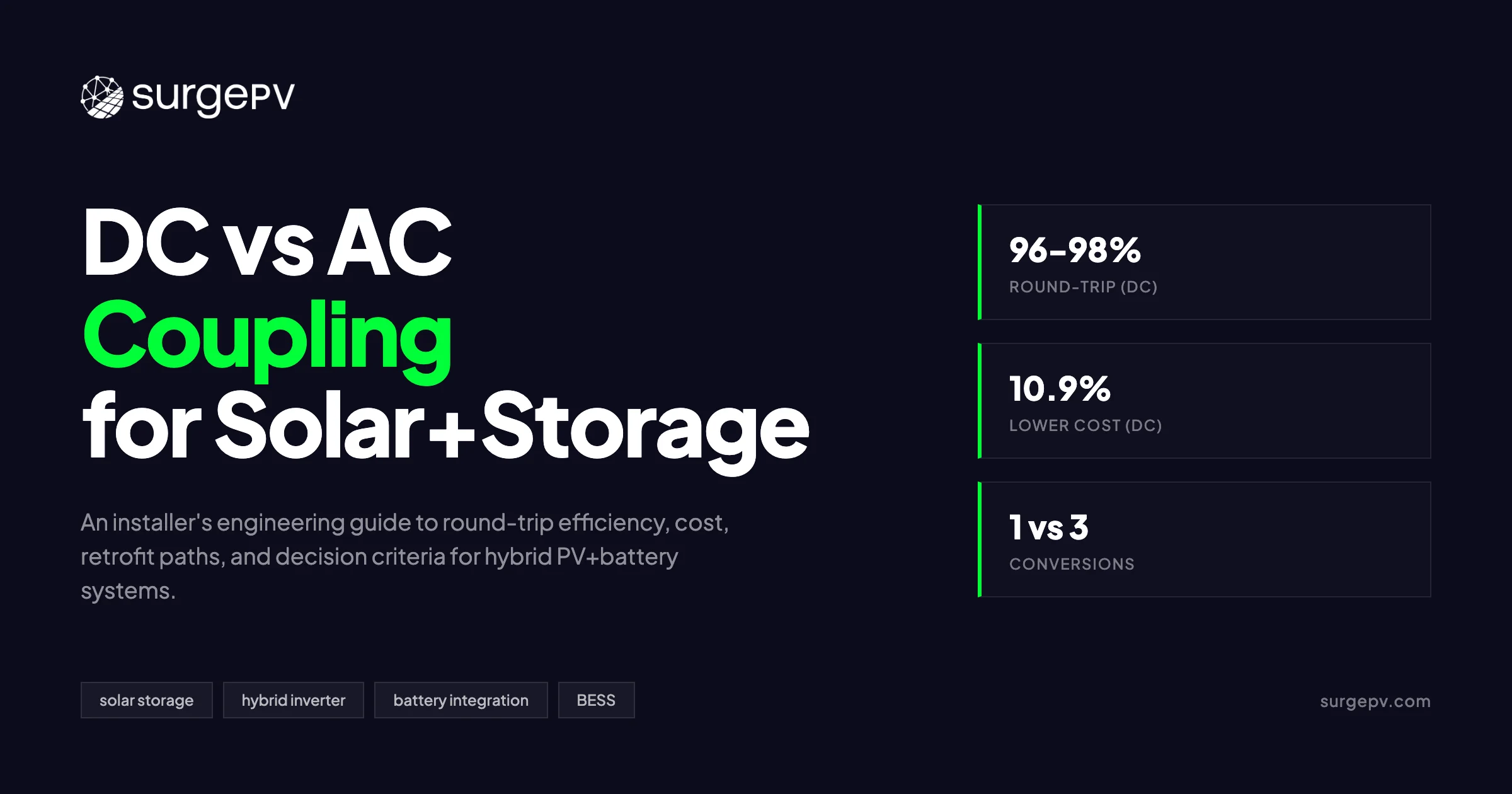
DC coupling sends PV power straight to the battery via a DC-DC converter, then inverts once to AC for the home. AC coupling inverts PV to AC first, then rectifies it back to DC for the battery, then inverts again on discharge — three conversions versus one. DC-coupled hybrids cost 10-15% less on new builds and achieve 96-98% round-trip efficiency. AC coupling dominates retrofits because it preserves the existing string inverter.
In this guide:
- How DC-coupled and AC-coupled solar+storage actually work
- Round-trip efficiency: the 4-point gap that decides 25-year yield
- DC oversizing and clipping recovery: the hidden yield gain
- Cost comparison: new build vs retrofit (hardware + labor + BOS)
- Code, safety, and warranty paths
- Decision matrix: which coupling for which project
- Named inverter and battery pairings (reference table)
- Commissioning and monitoring: what changes between topologies
- Common mistakes installers make on coupling decisions Read more about Agricultural Solar Case Study. For France-specific information, see Floating Solar Farms France.
How DC-Coupled and AC-Coupled Solar+Storage Actually Work
DC-coupled systems connect the photovoltaic array and battery to a shared DC bus inside a hybrid inverter. AC-coupled systems keep the PV array on its own string inverter and add a separate battery inverter that charges and discharges the battery from the AC bus. The difference is not just wiring — it is the number of power-conversion stages every kilowatt-hour must survive.
In a DC-coupled topology, power flows from the PV array through the MPPT inputs of a hybrid inverter. The hybrid inverter contains a DC bus. When the battery needs charging, a DC-DC converter steps the PV voltage to the battery voltage and pushes current directly into the pack. When the battery discharges, DC power from the battery travels back through the same DC bus, the hybrid inverter performs a single DC-to-AC conversion, and the resulting AC feeds the load or the grid. The path is: PV array → MPPT → DC bus → DC-DC converter → battery → DC bus → hybrid inverter → AC load/grid. For energy that goes straight from PV to the home without touching the battery, there is only one conversion: PV DC to AC.
In an AC-coupled topology, the PV array connects to a standard string inverter. The string inverter converts PV DC to AC and pushes it onto the AC bus. When the battery needs charging, a separate battery inverter — sometimes called a battery charger or energy storage inverter — rectifies AC back to DC and feeds the battery. When the battery discharges, the battery inverter performs a second DC-to-AC conversion to power the home. The path is: PV array → string inverter (DC→AC) → AC bus → battery inverter (AC→DC) → battery → battery inverter (DC→AC) → AC load/grid. Every kilowatt-hour that enters and exits the battery passes through at least three conversion stages: the string inverter, the battery charger, and the battery inverter.
MPPT location differs too. In DC coupling, the hybrid inverter owns the MPPT trackers. The PV array and battery share the same DC bus voltage window, which means the hybrid inverter must accommodate both the open-circuit voltage of the strings and the operating voltage of the battery. In AC coupling, the string inverter owns MPPT. The battery inverter does not need to track maximum power point — it simply rectifies AC at whatever voltage the grid or the string inverter presents. This separation is why AC coupling is more forgiving of voltage mismatches between PV and battery.
Grid-forming versus grid-following is a topology distinction that matters off-grid. A grid-forming inverter can create its own AC waveform and energize a home during a grid outage. Most DC-coupled hybrid inverters are grid-forming by design because they must manage the DC bus voltage in islanded mode. AC-coupled battery inverters may be grid-forming or grid-following. If the battery inverter is grid-following, it cannot start up during a blackout unless the string inverter — which is usually grid-following — is already producing. That is why whole-home backup with AC coupling typically requires a multimode battery inverter with grid-forming capability and a transfer switch that isolates the home from the grid. See AC Coupled vs DC Coupled Battery Solar for detailed guidance.
A hybrid inverter is not the same as a string inverter plus a battery inverter. A hybrid inverter integrates the PV MPPT, the DC-DC battery converter, and the AC inverter stage in one enclosure. It has one firmware stack, one monitoring portal, and one warranty. A string-plus-battery-inverter combo has two enclosures, two firmware stacks, two monitoring portals, and two warranties. The hybrid inverter eliminates the separate battery inverter but adds complexity to the DC bus design.
One misconception persists: that AC coupling is an older, legacy architecture and DC coupling is the modern replacement. Both are mature. AC coupling has dominated the retrofit market since the early 2010s because it avoids inverter replacement. DC coupling has dominated new-build residential and utility-scale projects since the mid-2010s because it reduces conversion losses and balance-of-material cost. Neither is obsolete. The right choice depends on project type, not calendar year.
Installers evaluating solar design software should verify that their tool models both topologies with separate efficiency curves and BOS cost stacks. A solar proposal software that defaults to AC coupling for every project will understate yield and overstate cost on new-build DC-coupled designs.
Round-Trip Efficiency: The 4-Point Gap That Decides 25-Year Yield
DC-coupled systems achieve 96-98% round-trip efficiency. AC-coupled systems achieve 90-94%. The gap comes from conversion-stage losses: each AC-to-DC or DC-to-AC conversion costs 2-3% efficiency. DC coupling avoids two of those conversions by keeping PV and battery on the same DC bus.
Round-trip efficiency (RTE) is simple math: energy out of the battery divided by energy into the battery, expressed as a percentage. If you push 10 kWh into a battery and get 9.4 kWh back, the RTE is 94%. Every inverter datasheet, every battery spec sheet, and every utility interconnection application should reference RTE. It is the single most important performance metric for a solar-plus-storage system because it compounds daily across 15 to 25 years.
DC-coupled real-world RTE: 96-98%. The pathway has two stages when charging from PV: a DC-DC converter (99% efficient) and the hybrid inverter on discharge (98% efficient). Multiply the stages and you get roughly 97%. Manufacturer claims align: SolarEdge cites 94.5% system RTE for its DC-coupled Home Battery; Tennessee Advanced Energy calculated 95.1% for DC coupling using 99% DC-DC charge, 99% DC-DC discharge, and 98% inverter discharge. At utility scale, MDPI Energies measured 97.02% annual average efficiency for DC-coupled BESS-side architecture.
AC-coupled real-world RTE: 90-94%. The pathway has four to six stages. EPRI published a stacked-calculation example: 0.98 × 0.99 × 0.99 × 0.98 × 0.98 × 0.98 × 0.99 − 0.02 = 0.87, or 87%. That is a conservative utility-scale assumption. Residential AC-coupled systems with high-quality inverters typically land at 90-94%. Tesla Powerwall 2 claims 90% RTE. Enphase IQ Battery 5P claims 90% AC RTE. Tennessee Advanced Energy calculated 92.2% for AC coupling.
Where do the losses hide? Each inverter stage — whether rectifying AC to DC or inverting DC to AC — loses 1-3% to switching losses, transformer losses, and standby consumption. A string inverter at 98% efficiency drops to 96% at part load. A battery inverter at 98% efficiency does the same. Stack three of them and you are at 92-94% before the battery’s own internal resistance adds its penalty. Transformer-coupled battery inverters add a fourth stage, pushing AC-coupled RTE under 90% in some architectures.
Here is a worked example. A 10 kWp residential array with a 13.5 kWh battery cycles 5,500 kWh per year through storage in a high-self-consumption household. At 97% RTE (DC), the system loses 165 kWh per year to conversion. At 93% RTE (AC), it loses 385 kWh per year. The delta is 220 kWh per year. Over 25 years at $0.30 per kWh, that is $1,650 in lost energy value from AC coupling on one average-sized residential system. Scale that to a 500 kW C&I project with 1 MWh cycling 200 MWh per year and the 4-point gap becomes a $24,000 annual revenue difference under time-of-use arbitrage.
Caveats matter. Real-world RTE depends on duty cycle, part-load efficiency curves, self-consumption ratio, and climate. An inverter rated at 98% peak efficiency may run at 92% when the battery trickle-charges at 200 W. High ambient temperatures derate both inverter and battery performance. High C-rate discharge increases resistive losses inside the pack. Auxiliary loads — BMS, cooling fans, communication modules — consume parasitic power that most headline RTE figures omit.
AC coupling only penalizes stored energy. PV power that flows straight from the array to the home through the string inverter avoids the battery path entirely. In a low-self-consumption household where most PV production is exported, the RTE gap matters less because little energy passes through the battery. In a high-self-consumption or off-grid household where 70-90% of PV production transits the battery, the gap is decisive.
Pro Tip
When modeling RTE in your generation and financial tool, apply a temperature and part-load derating factor of 0.96-0.98 to the manufacturer headline figure. The headline number is measured at 25°C and 50% rated power. Real roofs are not laboratory benches.
DC Oversizing and Clipping Recovery: The Hidden Yield Gain
DC-coupled hybrid inverters can route clipped DC power straight to the battery instead of wasting it. On a 10 kWp array with a 7.6 kW inverter at 1.32:1 DC/AC ratio, 3-5% of annual production is normally clipped. DC coupling recovers most of that energy. AC-coupled systems cannot recover clipping because the loss happens upstream of the inverter limit.
Clipping occurs when the DC power from the PV array exceeds the maximum AC output of the inverter. The inverter caps its output and the excess DC is lost as heat in the IGBTs. Installers intentionally oversize arrays to capture more morning and afternoon production, accepting a small midday clip. The economics of oversizing are well established: a DC/AC ratio of 1.2 to 1.4 typically maximizes NPV on fixed-tilt residential systems.
In a DC-coupled system, the hybrid inverter sees the full DC array current. When the array produces more DC than the inverter can push to AC, the excess does not have to be clipped. The DC-DC converter diverts the surplus straight to the battery. The battery charges at the clipped rate, storing energy that would otherwise be lost. NREL and Sandia modeling found that for a DC/AC ratio of 1.85, the DC-connected battery produced an NPV 13% higher than the AC-connected battery because it captured clipped energy.
AC-coupled systems cannot do this. The string inverter clips the DC array at its AC-rated limit. Any excess DC is lost before it reaches the AC bus. The battery inverter sits downstream of that clip. It can only charge from whatever AC power the string inverter produces. If the string inverter is already maxed out, the battery gets nothing from the clipped portion. The only workaround is to oversize the string inverter — which defeats the cost savings of oversizing the array.
The combined effect stacks two yield wins for DC coupling on new builds. First, the higher round-trip efficiency saves 3-4% on every kilowatt-hour cycled through the battery. Second, clipping recovery adds another 2-4% on annual production for systems with DC/AC ratios above 1.3. On a 10 kWp system in a sunny climate, that can mean an extra 300-500 kWh per year.
Practical limits exist. The hybrid inverter’s DC input rating must accommodate the oversizing. If the inverter accepts 150% DC oversizing, a 10 kW AC-rated hybrid can handle 15 kWp of PV. If it only accepts 120%, the limit is 12 kWp. String sizing math must also respect the MPPT voltage window: the open-circuit voltage of the string at record low temperature must stay under the inverter’s maximum DC input voltage, and the maximum power voltage at high temperature must stay above the minimum MPPT voltage. Products like SolarEdge Energy Hub allow up to 200% DC oversizing. Sungrow SH-RT series allows 150%. GoodWe ET PLUS+ allows 150-200% depending on model.
NREL’s “PV Inverter Loading Ratios” research confirms that optimal DC/AC ratios have risen as module costs fell and inverter costs remained flat. In markets with aggressive net-metering export reductions — like California under NEM 3.0 — clipping recovery to battery storage is now a standard design strategy. A solar design tool that does not model clipping recovery to battery is understating DC-coupled project yield. See Adding Battery Storage Services for detailed guidance.
Cost Comparison: New Build vs Retrofit (Hardware + Labor + BOS)
DC-coupled new-build residential systems cost 10-15% less than AC-coupled equivalents. NREL benchmarked a 7 kW PV + 12.5 kWh storage system at $30,450 DC-coupled and $33,756 AC-coupled — a $3,306 delta. On retrofits, AC coupling is usually cheaper because it preserves the existing inverter and avoids 8-16 hours of replacement labor.
| Scenario | DC-Coupled | AC-Coupled | Delta |
|---|---|---|---|
| New build hardware (10 kWp + 13.5 kWh) | ~$24,500 | ~$28,000 | ~14% higher (AC) |
| New build labor hours | 12-16 hrs | 16-20 hrs | ~25% higher (AC) |
| Retrofit to existing solar | Often impractical | Standard approach | — |
| BOS (combiner, disconnects, conduit) | Lower | Higher | ~$400-800 |
| Total install cost (US residential, 7 kW + 12.5 kWh) | $30,450 | $33,756 | 10.9% higher (AC) |
Source data draws from NREL cost benchmark reports, Wood Mackenzie U.S. Energy Storage Monitor, and aggregated installer quote data. The DC-coupled advantage comes from eliminating one entire inverter. A hybrid inverter replaces both the string inverter and the battery inverter. Fewer enclosures mean fewer disconnects, less conduit, smaller combiner boxes, and less wall space.
The 10.9% NREL delta is for a specific 7 kW + 12.5 kWh configuration. The gap widens on larger systems where the battery inverter cost scales with power rating. A 20 kW residential system with 27 kWh of storage might see a 12-15% DC cost advantage. The gap narrows on small systems where the fixed cost of permitting, interconnection, and design dominates.
AC coupling’s retrofit advantage is structural. A homeowner with a 3-year-old string inverter under warranty does not want to replace it. An AC-coupled battery — Tesla Powerwall 2, Enphase IQ Battery, Sonnen eco — connects to the existing AC bus with no change to the PV side. Labor is 4-8 hours: mount the battery, wire the battery inverter to a subpanel or load-side connection, configure the monitoring app, and commission. A DC-coupled retrofit requires removing the existing inverter, installing a hybrid inverter, rewiring PV strings to the new MPPT inputs, pulling new DC homeruns if the voltage windows differ, and re-permitting the DC side. Labor jumps to 8-16 hours. The existing inverter warranty is voided by removal. The customer may need a new permit or interconnection agreement if the inverter make and model change.
Hidden costs appear on both sides. DC coupling’s single inverter is a single point of failure. If the hybrid inverter fails, both PV production and battery backup stop until replacement. That risk is insurable but real. AC coupling’s separate inverters provide redundancy: if the battery inverter fails, the PV array keeps producing. If the string inverter fails, the battery can still charge from the grid.
For C&I time-of-use arbitrage projects, the efficiency advantage of DC coupling often pays back the upfront hardware delta within 5-7 years. A 500 kW system cycling 200 MWh per year saves $12,000-18,000 annually in reduced conversion losses. Over 15 years, the NPV of that savings exceeds the initial $15,000-25,000 hardware premium of DC coupling.
Code, Safety, and Warranty Paths
NEC Article 706 governs energy storage systems in the US. The 120% rule in NEC 690.8 limits AC-coupled backfeed to 120% of busbar rating. UL 9540 and UL 9540A test fire safety for ESS. IEC 62933 and IEC 62619 govern EU battery systems. In the UK, Ofgem G98/G99 sets grid-connection rules. Each topology faces slightly different compliance paths. Read more about Battery Solar System Design UK. For United Kingdom-specific compliance details, see United Kingdom comparisons/mcs-vs-non-mcs. For United Kingdom-specific compliance details, see United Kingdom comparisons/solar-design-software.
In the United States, NEC Article 706 defines an energy storage system as “one or more components assembled together capable of storing energy for use at a future time.” It applies to permanently installed ESS above 50 V AC or 60 V DC. Article 706.20(A)(5) requires that DC-to-DC converter output current be sized to the maximum rated continuous output current of the converter. Article 706.23(C) mandates the same for charge controller and DC-DC converter output conductor ampacity. For DC-coupled installers, this means the DC bus cabling between hybrid inverter and battery must be sized to the converter’s continuous rating, not the battery’s nominal charge rate.
The 120% rule in NEC 690.8 is the most common AC-coupled compliance hurdle. It states that the sum of PV breaker rating plus main breaker rating must not exceed 120% of the busbar rating. On a 200 A panel with a 200 A main breaker, the maximum PV backfeed breaker is 40 A (120% × 200 A = 240 A; 240 A − 200 A = 40 A). An AC-coupled battery adds a second backfeed source. If the PV breaker is 40 A and the battery inverter breaker is 30 A, the total is 70 A — which exceeds the 40 A limit. Installers must either downsize the main breaker (to 175 A, allowing 65 A of backfeed), upgrade the panel, or use a supply-side tap. DC-coupled systems avoid this issue because the battery does not backfeed through the AC service panel — it feeds through the hybrid inverter’s AC output, which is treated as a single interconnection point.
NEC 2026 updates add BMS documentation requirements, updated short-circuit current rating (SCCR) labeling, and lithium-ion installation clearances. New Section 710.15 addresses the electrical interface between distributed energy resources — PV, battery, and EV — requiring documentation for aggregate back-feed and peak export capacity. This matters for DC-coupled systems with integrated EV charging because the hybrid inverter, battery, and EV charger share a DC bus whose aggregate fault current must be documented.
UL 9540 is the safety standard for energy storage systems. UL 9540A is the fire safety test method. The two standards apply differently by topology. A DC-coupled hybrid inverter + battery pair is tested as a system. An AC-coupled battery inverter + battery may be tested separately from the PV inverter. SolarEdge claims its Home Battery was “one of the first residential batteries to pass the strictest UL 9540A unit level test”. Installers should verify that the specific battery + inverter combination they specify has a UL 9540 system-level listing, not just individual component listings.
IEC 62619 covers lithium-ion cell and battery safety for industrial applications. IEC 62933 provides terminology and performance assessment for electrical energy storage systems. IEC 61730 governs PV module safety qualification. In the EU, a DC-coupled hybrid inverter must comply with IEC 62109 for safety of power converters used in PV power systems.
Country-specific interconnection adds more layers. In the UK, Ofgem G98 covers installations under 16 A per phase; G99 covers larger installations. MCS certification is required for battery installation to qualify for export tariffs. DC-coupled hybrids must be G99-compliant and MCS-certified as a system. In Germany, VDE-AR-N 4105 governs generator connection to low-voltage networks. The EEG (Renewable Energy Sources Act) provides investment subsidies for storage up to 50 kWh. Hybrid inverters must pass VDE certification for grid support functions including frequency-watt and volt-watt curves. In Australia, AS/NZS 4777.2 sets grid-connection requirements. The CEC maintains an approved product list; only listed inverters qualify for STC incentives. Most DC-coupled hybrids from Sungrow, GoodWe, and Fronius are CEC-approved. In the US, CPUC Rule 21 governs California interconnection. NEM 3.0 export rates make self-consumption optimization critical, which favors DC coupling’s higher round-trip efficiency for stored energy. Also see: Germany solar subsidies.
Warranty topology is often overlooked. DC coupling means the PV and battery share a single inverter warranty. If the hybrid inverter fails after year 6, both solar production and battery backup are offline until repair or replacement. The customer has one vendor to call — which is efficient when the vendor is responsive and painful when they are not. AC coupling means independent warranties: the PV string inverter from one manufacturer, the battery from another, the battery inverter from a third. Redundancy is higher. Coordination is harder. If a battery inverter fails under warranty but the battery itself is fine, the customer still has solar production while waiting for the swap.
Decision Matrix: Which Coupling for Which Project
New residential builds with simultaneous PV and battery should default to DC-coupled hybrid inverters. Retrofits with existing solar should default to AC-coupled batteries. C&I time-of-use arbitrage favors DC coupling for cycle efficiency. Off-grid and island systems require grid-forming DC hybrids. Whole-home backup with per-panel resilience favors AC-coupled microinverter architectures.
| Project Type | Recommendation | Why |
|---|---|---|
| New residential, no existing PV | DC-coupled hybrid | Highest efficiency, lowest BOM, clipping recovery |
| Existing PV, adding battery | AC-coupled | Preserves string inverter warranty, avoids rewiring |
| C&I 30-500 kW with TOU arbitrage | DC-coupled | Cycle efficiency drives 10-year ROI |
| Off-grid / island | DC-coupled (grid-forming) | Required for black-start and bus voltage control |
| Microgrid / community-scale | DC or hybrid AC | Depends on central vs distributed bus architecture |
| Whole-home backup priority | AC-coupled (Enphase IQ8 family) | Per-microinverter resilience during partial shading |
| Highly shaded array | AC + DC optimizers OR DC + multi-MPPT hybrid | MPPT count matters more than coupling topology |
New residential, no existing PV: This is the easiest call. A DC-coupled hybrid inverter delivers 96-98% RTE, costs 10-15% less in hardware, and recovers clipped energy on any DC/AC ratio above 1.2. Products like the Tesla Powerwall 3, SolarEdge Energy Hub, Fronius GEN24 Plus, and Sungrow SH-RT series are purpose-built for this segment. The installer runs one AC homerun from the hybrid inverter to the main panel, one DC homerun from the rooftop junction box to the hybrid inverter, and one DC cable from the hybrid inverter to the battery. Commissioning happens on a single app.
Existing PV, adding battery: AC coupling is the standard retrofit path. The existing string inverter stays in place, preserving its warranty and its original interconnection agreement. The battery inverter connects to the AC bus on the load side of the main panel or via a critical-loads panel. Tesla Powerwall 2, Enphase IQ Battery, and Sonnen eco are the most common retrofit choices. The only DC-coupled retrofit that makes sense is when the existing string inverter is already at end-of-life or the customer wants to repower the entire system.
C&I 30-500 kW with time-of-use arbitrage: DC coupling wins on economics. A C&I battery cycles 250-365 times per year. A 4-point RTE gap compounds to serious revenue loss. At $0.25 per kWh peak-to-off-peak spread, a 500 kW / 1 MWh system cycling once daily loses $36,500 per year at 92% RTE versus $24,000 at 97% RTE. Over 10 years, that $125,000 delta dwarfs the $20,000 upfront hardware savings of AC coupling. DC-coupled commercial hybrids from Sungrow, Huawei, and SMA dominate this segment.
Off-grid / island: Grid-forming DC hybrids are mandatory. The inverter must create and stabilize the AC waveform. The battery must provide bus voltage reference when solar production is low. Victron MultiPlus-II, SMA Sunny Island, and select Fronius and Deye models offer true off-grid capability. AC coupling is possible but requires a grid-forming battery inverter and careful coordination with the string inverter’s start-up sequence.
Microgrid / community-scale: The answer depends on bus architecture. A central DC bus with one large hybrid inverter favors DC coupling. A distributed architecture with multiple PV inverters and battery inverters on a shared AC bus favors AC coupling. The decision is an electrical engineering question about fault current, protection coordination, and redundancy — not a product preference.
Whole-home backup priority: AC-coupled microinverter systems offer unique resilience. Enphase IQ8 microinverters can form microgrids during daylight hours even if the IQ Battery is depleted, because each panel operates as its own island. A DC-coupled system with one hybrid inverter has no daylight resilience if the battery is dead and the inverter is offline. For customers in hurricane or wildfire zones where multi-day outages are likely, this per-panel resilience can justify the lower RTE of AC coupling.
Highly shaded arrays: Coupling topology is secondary to MPPT granularity. A DC-coupled hybrid with 3 MPPTs and module-level optimizers will outperform an AC-coupled system with one string inverter and no optimizers. An AC-coupled microinverter system will outperform both on complex roofs. The right question is “how many independent MPPTs do I have?” not “AC or DC?”
Named Inverter and Battery Pairings (Reference Table)
The table below lists 13 manufacturers, their coupling topology, continuous power rating, and battery compatibility. Verify voltage windows and oversizing limits in the latest datasheet before specifying — manufacturers update firmware-unlockable features quarterly.
| Manufacturer | Model | Coupling | Continuous (kW) | Battery Compatibility |
|---|---|---|---|---|
| Enphase | IQ Battery 5P + IQ8 microinverters | AC | 3.84 | Enphase only |
| Fronius | Symo GEN24 Plus + BYD HVS/HVM | DC (hybrid) | 6-10 | BYD HV |
| Generac | PWRcell M6 | DC (hybrid) | 7.6-11 | PWRcell battery only |
| GoodWe | ET Series + LX A5.0 | DC (hybrid) | 5-10 | GoodWe Lynx |
| Huawei | SUN2000 L1 + LUNA2000 | DC (hybrid) | 3.68-10 | LUNA2000 |
| LG | LG ESS Home 8/10 | DC (hybrid) | 5-10 | LG RESU |
| SMA | Sunny Tripower Smart Energy + BYD | DC (hybrid) | 5.0-10.0 | BYD HV |
| SolarEdge | Energy Hub + SE Home Battery | DC + DC opt | 7.6-11.4 | SolarEdge battery |
| Sonnen | sonnenCore+ | AC | 4.8 | Internal LFP |
| Sungrow | SH RT + SBR HV | DC (hybrid) | 5-25 | SBR HV |
| Tesla | Powerwall 3 (with PV) | DC (hybrid) | 11.5 | Internal LFP |
| Tesla | Powerwall 2 (retrofit) | AC | 5.0 | Internal NMC |
| Victron | MultiPlus-II + GX + LiFePO4 | AC + DC hybrid | 3-15 | Multi-vendor |
Enphase IQ Battery 5P is a purely AC-coupled modular system. Each 5P unit contains embedded IQ8D-BAT microinverters. The AC RTE is 90%; the DC cell-level RTE is 96%. Stacking is modular but limited to same-generation pairing — a 5P cannot stack with a 10C. Enphase ecosystem loyalty is strong among microinverter customers because the monitoring portal already covers PV and battery without extra registration.
Fronius GEN24 Plus is a DC-coupled hybrid with “PV Point & Full Backup” capability via an external switching device. It is compatible with BYD Battery-Box Premium HVS and HVM high-voltage batteries. The UP.storage software upgrade allows retrofit storage activation on existing GEN24 installations — a rare case where DC coupling can be added without full inverter replacement.
SolarEdge Energy Hub allows up to 200% DC oversizing and pairs with the SolarEdge Home Battery at 400 V high voltage. The system RTE is 94.5%. Module-level optimizers enable per-panel MPPT, which is valuable on shaded roofs. The downside is vendor lock-in: the battery only works with SolarEdge inverters.
Tesla Powerwall 3 marks a topology shift. Powerwall 2 was AC-coupled with 5 kW continuous output and 90% RTE. Powerwall 3 integrates a solar inverter with 3 MPPTs, enabling DC-coupled operation at up to 8 kW charge rate and 11.5 kW continuous output. It can still retrofit AC-coupled to existing systems. The internal battery is LFP.
Sigenergy SigenStor is a DC-coupled all-in-one that includes an optional 25 kW bidirectional EV DC charging module. It charges EVs directly from the DC bus, avoiding the triple-conversion penalty of AC EV chargers. This makes it the most V2H-ready residential product on the market.
Victron MultiPlus-II is unique in offering both AC and DC hybrid paths. The MultiPlus-II is an AC-coupled bidirectional inverter/charger. Combined with a Victron MPPT solar charge controller and a GX device, it can operate as a DC-coupled off-grid system. It is the go-to choice for boats, cabins, and DIY off-grid builds because it accepts multi-vendor batteries.
Model Both Coupling Topologies in the Same Project File
SurgePV lets installers compare DC and AC coupled architectures side-by-side with real yield, ROI, and BOM data — before sending the proposal.
Book a DemoNo commitment required · 20 minutes · Live project walkthrough
For a direct comparison, see Arka 360 vs SurgePV.
Commissioning and Monitoring: What Changes Between Topologies
DC-coupled systems commission through a single inverter portal. AC-coupled systems require two portals, two firmware streams, and careful coordination of CT placement. Modbus and SunSpec mapping differ. Off-grid black-start is only available on grid-forming DC hybrids.
DC coupling commissioning is simpler in scope but denser in DC safety checks. The installer configures MPPT string sizes in the hybrid inverter portal, verifies DC bus voltage at the battery terminals under charge and discharge, confirms closed-loop BMS handshake between inverter and battery, and runs an SOC calibration cycle. Most hybrid inverters — SolarEdge, Sungrow, Fronius, Tesla — handle this through a single smartphone app or web portal. Firmware updates come from one vendor. Remote troubleshooting requires one login.
AC coupling commissioning splits across two devices. The existing string inverter keeps its original portal — SolarEdge SetApp, SMA Sunny Portal, or generic Modbus logger. The battery inverter adds a second portal — Tesla app, Enphase Enlighten, or Sonnen app. The installer must register both, verify that the battery inverter correctly reads PV production data (usually via CT clamps or Modbus), and confirm that the two inverters do not fight each other during grid-forming tests. Firmware updates come on two different schedules. A string inverter firmware update that changes export power curves can break the battery inverter’s charge logic if the two vendors do not coordinate.
CT placement is a common commissioning error. On DC-coupled systems, the production meter measures DC current at the hybrid inverter input. The net meter measures AC current at the point of interconnection. The math is simple: production minus consumption equals net export. On AC-coupled systems, the production CT must clamp the AC output of the string inverter, not the battery inverter. The net meter must clamp the main service conductor. If the installer clamps the battery inverter output by mistake, the system will report battery discharge as PV production and the self-consumption metrics will be wrong.
Frequency-watt and volt-watt curves must be set on each active inverter. In a DC-coupled system, the hybrid inverter handles all grid support functions. In an AC-coupled system, both the string inverter and the battery inverter must have matching curves. If the string inverter trips on over-frequency at 50.5 Hz but the battery inverter rides through to 52 Hz, the battery will attempt to export into a dead grid — a safety hazard.
Off-grid black-start is only possible with grid-forming DC hybrids. After a prolonged outage, the battery must establish AC voltage and frequency before the PV array can reconnect. The hybrid inverter does this automatically. AC-coupled systems need a grid-forming battery inverter with black-start capability. If the battery inverter is grid-following, it cannot restart the system — the homeowner must wait for grid return or use a manual generator start.
SurgePV’s solar design software exports commissioning checklists linked to the topology selected in the project file. The checklist for a DC-coupled Sungrow SH-RT system includes different voltage verification steps than the checklist for an AC-coupled Enphase IQ Battery system. This reduces callbacks and warranty claims.
Common Mistakes Installers Make on Coupling Decisions
Even experienced crews make these errors at the bid stage. Most are avoidable with five minutes of math before sending the proposal.
-
Quoting AC coupling on a new build because it is “what we know.” AC coupling is the safe choice for retrofits. On new builds, it adds $3,000+ in hardware and sacrifices 4 points of RTE. Default to DC coupling unless the customer explicitly requires AC-coupled products.
-
Sizing the battery inverter to the PV array size instead of the battery C-rate. A 10 kWp array does not need a 10 kW battery inverter. A 13.5 kWh battery with 0.5C rate only needs 6.75 kW of inverter. Oversizing the battery inverter adds cost and reduces part-load efficiency.
-
Ignoring DC bus voltage windows on hybrid inverters. A BYD HVS battery operates at 160-500 V. A Fronius GEN24 Plus accepts 160-531 V. That works. A 48 V LV battery on a high-voltage hybrid inverter does not. Voltage mismatch is the leading cause of DC-coupled commissioning failures.
-
Failing the 120% rule on AC retrofit at the main service panel. Adding a 30 A battery breaker to a panel already at its 120% limit creates a code violation. Always recalculate busbar loading before quoting AC-coupled retrofits.
-
Mismatching battery chemistry to inverter charge profile. LFP batteries charge at a constant voltage of 3.6 V per cell. NMC batteries charge at 4.2 V per cell. An inverter configured for NMC will overcharge and potentially thermal-runaway an LFP pack. Verify BMS communication protocol — CAN, RS485, or proprietary — before pairing.
-
Selling a hybrid inverter to a customer who already has a 5-year-old string inverter. The customer will pay for inverter replacement labor they did not need. Quote AC coupling first on retrofits. Only pitch DC coupling if the existing inverter is failing or the customer wants a full repower.
-
Assuming AC coupled equals backup capable. Most AC-coupled battery inverters are grid-following. They will not power the home during an outage without a multimode inverter and a transfer switch. Verify backup capability explicitly — do not assume it from the coupling topology.
-
Not modeling clipping recovery on DC coupling proposals. A DC-coupled system with 1.5:1 DC/AC ratio recovers 2-4% more annual production than the same array on an AC-coupled system. If your solar proposal software does not model this, you are understating DC-coupled value.
Conclusion
- For new residential and C&I builds, default to DC-coupled hybrid unless there is a specific reason against it.
- For retrofit jobs, AC coupling preserves existing-inverter warranty and remains the right call roughly 80% of the time.
- Run both topologies through your design and proposal tool before quoting — the cost and yield delta typically swings 10-15% in either direction.
The coupling decision is not a consumer preference question. It is a design-engineering calculation with quantified inputs: conversion-stage efficiency, DC/AC ratio, clipping recovery value, labor hours, inverter warranty status, and interconnection code path. Installers who treat it as math win bids. Installers who treat it as opinion lose margin.
Frequently Asked Questions
Is DC coupling more efficient than AC coupling?
Yes. DC-coupled systems achieve 96-98% round-trip efficiency because photovoltaic power travels from the array to the battery via a single DC-DC conversion stage. AC-coupled systems force the same energy through three or more conversions — string inverter, battery charger, and battery inverter — dropping real-world round-trip efficiency to 90-94%. Over 25 years, a 4% efficiency gap on a typical residential battery cycle can cost $1,500 or more in lost energy value.
Can I retrofit a DC-coupled battery to existing solar?
Usually no. Retrofitting DC coupling to an existing array almost always requires replacing the existing string inverter with a hybrid inverter, rewiring PV strings to the new DC bus, and reconfiguring MPPTs. Labor runs 8-16 hours versus 4-8 hours for AC-coupled retrofit. For this reason, AC coupling is the standard retrofit path — it preserves the existing inverter warranty and avoids pulling new conduit to the rooftop junction box.
Is the Tesla Powerwall AC or DC coupled?
Powerwall 2 is AC-coupled. Powerwall 3 is DC-coupled when installed with new solar, but can also operate AC-coupled in retrofit mode. Powerwall 3 contains an integrated solar inverter with 3 MPPTs, enabling direct DC battery charging from the PV array at up to 8 kW — significantly faster than the 5 kW AC-coupled charge rate of Powerwall 2.
Does AC coupling work during a grid outage?
Only if the AC-coupled system includes a grid-forming battery inverter with anti-islanding and automatic transfer switching. Many AC-coupled battery inverters — including most battery-only inverters without blackout capability — will not energize the home during an outage. Off-grid or whole-home backup applications should spec a grid-forming hybrid inverter or an AC-coupled multimode inverter explicitly rated for backup operation.
Which is cheaper, AC or DC coupling?
DC coupling is 10-15% cheaper for new-build residential systems. NREL benchmarked a 7 kW PV + 12.5 kWh storage system at $30,450 DC-coupled versus $33,756 AC-coupled — a $3,306 or 10.9% delta. The gap narrows or reverses on retrofit jobs because DC coupling requires inverter replacement. For commercial time-of-use arbitrage projects, the lower cycle efficiency of AC coupling can erase the upfront hardware savings within 5-7 years.