Quick Answer
A solar permit can stall for weeks over a single missing label on the single-line diagram. Each rejection adds 2–4 weeks and up to $2,000 in resubmission costs. NEC Article 690 and local AHJ requirements are the anchor: the SLD must show all significant components in the installation.
A solar permit can stall for weeks over a single missing label on the single-line diagram. The SLD is the first document a plan checker opens and the most common reason a permit gets flagged for correction.
A solar permit can stall for weeks over a single missing label on the single-line diagram. Each rejection adds 2–4 weeks and up to $2,000 in resubmission costs. NEC Article 690 and local AHJ requirements are the anchor: the SLD must show all significant components in the installation.
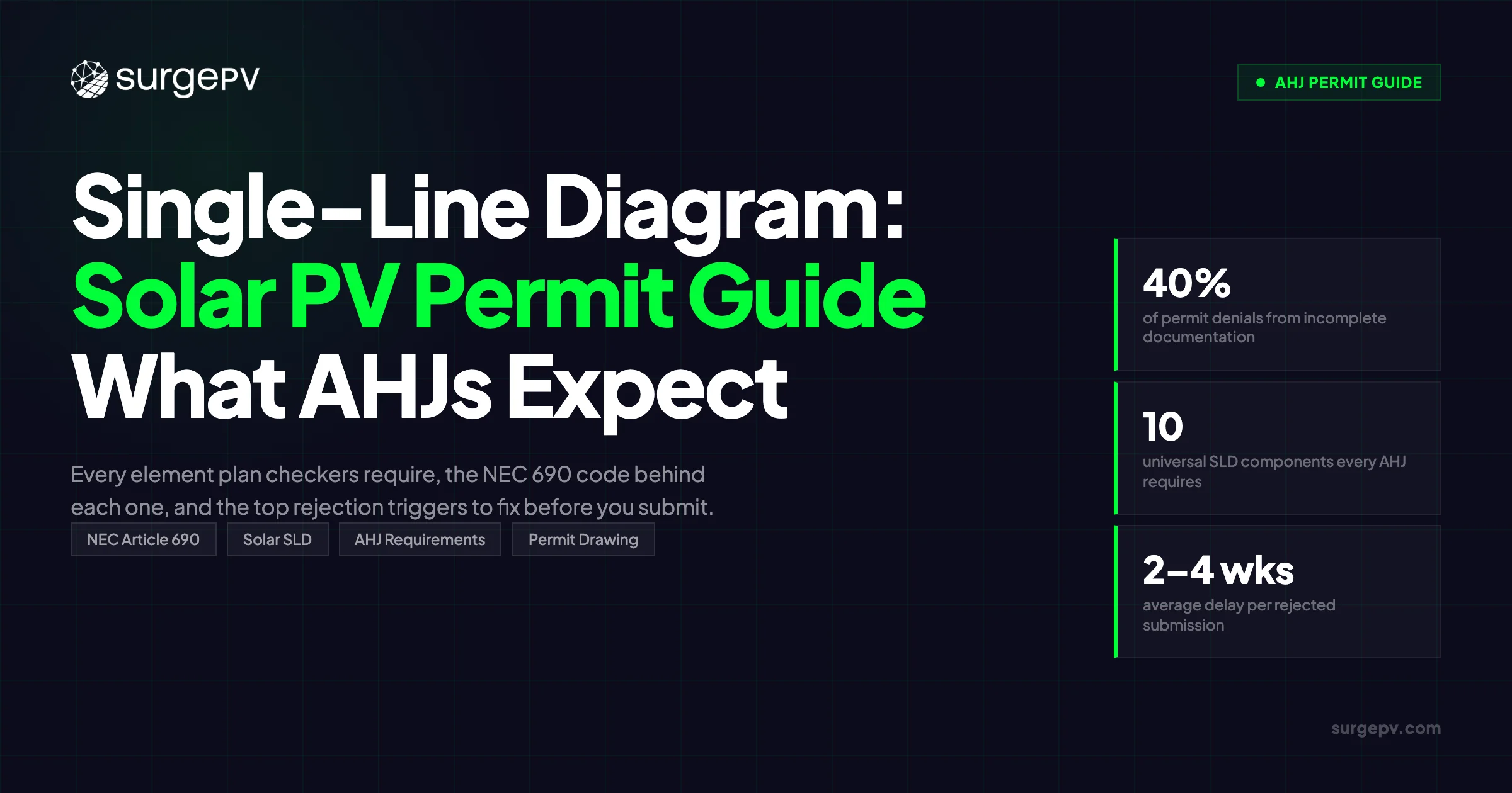
40% of permit denials trace back to incomplete documentation, and the SLD draws more correction requests than any other drawing in the package. Each rejection adds 2–4 weeks and up to $2,000 in resubmission costs.
This guide covers every element AHJ plan checkers require, the NEC Article 690 code sections behind each one, and a self-review checklist you can run before submission.
TL;DR
40% of solar permit denials stem from incomplete documentation, and the single-line diagram is the most scrutinized drawing in the package. This guide covers every component AHJ plan checkers require, the NEC code sections behind each one, and the most common rejection triggers — so you can hit first-pass approval.
What you’ll learn:
- The 10 universal components every residential and commercial SLD must show
- Which NEC Article 690 sections mandate specific SLD elements
- How string inverter and microinverter SLDs differ in notation
- What battery storage adds to the SLD and how to show AC vs. DC coupling
- The most common AHJ rejection reasons and how to avoid them
- How SolarAPP+ affects SLD requirements (it doesn’t eliminate them)
- How solar design software generates a permit-ready SLD in minutes
What Is a Single-Line Diagram in Solar PV?
A single-line diagram is a simplified electrical schematic that traces the complete circuit path from PV modules through the inverter to the utility interconnection point. It uses single lines to represent conductors and standardized symbols for equipment, giving plan checkers a clear picture of the system’s electrical architecture without the complexity of a full schematic.
NEC Article 690 and local AHJ requirements are the anchor: the SLD must show all significant components in the installation. That standard — significant components — drives the 10-element checklist every AHJ expects.
The SLD is distinct from a three-line diagram (which shows each phase conductor separately, typically required for commercial systems) and a riser diagram (which shows conduit routing between floors). For most residential systems, the SLD is the only electrical drawing required. Commercial systems frequently need both.
Three parties review the SLD:
- The AHJ plan checker — verifies NEC compliance and completeness before issuing the permit
- The fire marshal — checks rapid shutdown labeling, roof access pathways, and fire code compliance
- The utility engineer — confirms the interconnection point, meter type, and export control equipment
A permit-ready SLD satisfies all three. Learn more about the electrical SLD and its role in solar permitting.
The Complete SLD Element Checklist
The following 10 components are universally required. Missing any of them is the fastest way to earn a correction notice.
| Component | What Must Be Shown | Primary Code Reference |
|---|---|---|
| PV Modules / Strings | Manufacturer, model, quantity per string, strings per MPPT input, Voc, Isc, Pmax | NEC 690.4, NEC 690.7 |
| String Combiner Box | Location, fuse ratings per string, number of inputs, output current rating | NEC 690.9(C) |
| DC Disconnect | Voltage and current rating, fused or non-fused, location | NEC 690.15, NEC 690.17 |
| Inverter | Manufacturer, model, AC output rating (kW), DC input rating, quantity | NEC Article 690 |
| AC Disconnect | Rating (A), type, location within sight of the main service panel | NEC 705.12 |
| Production / Revenue Meter | Location, type (bidirectional net meter), utility meter number if known | Utility interconnection requirements |
| Utility Interconnection / MSP | Main service panel rating, busbar ampacity, back-fed breaker size or supply-side tap location | NEC 705.12(A)/(B) |
| Grounding / Bonding | AC and DC grounding electrode conductors (size and material), equipment grounding conductors, racking bonding method | NEC 690.41, NEC 690.47 |
| Overcurrent Protection | All OCPD ratings (breakers and fuses) in DC and AC circuits | NEC 690.9, NEC 240 |
| Rapid Shutdown Device | RSD type, initiator location, array boundary marking (≤30V outside / ≤80V inside boundary within 30 sec) | NEC 690.12 |
Conductor and Conduit Labels
Conductor labeling is where many SLDs fall short. Every segment of the circuit path needs:
- Conductor size and insulation type — e.g., “10 AWG THWN-2” or “PV wire, 12 AWG”
- Conduit size and type — e.g., “3/4” EMT” or “1” PVC Schedule 40”
- Number of conductors per raceway — e.g., “3 conductors in conduit”
- Grounding conductor size — shown separately from current-carrying conductors
The Frederick County, Colorado solar submittal requirements state it plainly: “Indicate all conductor sizes and insulation types, conduit sizes, fuse and circuit breaker ratings, inverter ratings, ground fault protection device (GFPD), AC and DC disconnect ratings. Specify the PV module’s nameplate short circuit current (Isc) and open circuit voltage (Voc).”
That is the bar. Most AHJs use equivalent language.
Title Block Requirements
Every permit-ready SLD needs a title block with:
- Site address and APN or parcel number
- Project title and system description (e.g., “5.4 kW PV + 10 kWh BESS”)
- Designer name, company, license number, and credentials
- Drawing number and version (the AHJ needs to know which version they are reviewing during resubmissions)
- Date and revision history
Some utilities (Jemena in Australia, for example) also require the NMI or utility account number directly on the SLD. Check your utility’s interconnection requirements for this. For the latest details on Australia, see Solar Energy in Australia. For Australia-specific compliance details, see Australia comparisons/lgc-vs-stc.
Pro Tip
Use a consistent drawing number format across all permit drawings — e.g., E-01 for the electrical SLD, S-01 for structural, A-01 for the site plan. Cross-reference these on each sheet. Plan checkers review multiple drawings at once, and consistent numbering reduces the chance of pulling the wrong version.
NEC Article 690 — The Code Sections Behind Each Element
Knowing which code section drives each SLD requirement helps you write accurate notes on the drawing and respond to plan checker corrections with precision.
| NEC Section | Requirement | What It Means for Your SLD |
|---|---|---|
| 690.7(A) | Maximum system voltage calculation | Show Voc × temperature correction factor. Label “PV string circuit” not “PV output circuit” in jurisdictions on NEC 2023. |
| 690.8 | Conductor ampacity = 156% × Isc (or 125% for continuous-duty inverter-listed equipment under NEC 2020+) | Show Isc on the SLD and include the ampacity calculation in a note or schedule. |
| 690.9(C) | Listed PV breakers or fuses in source/output circuits | Show all DC-side OCPD ratings. Unrated or undersized OCPDs are a common correction. |
| 690.12 | Rapid shutdown: ≤30V outside array boundary and ≤80V inside array boundary, both within 30 seconds | Show RSD type, initiator location (usually at service entrance), and draw the boundary. |
| 690.15 / 690.17 | Disconnecting means for all PV circuits | Show both AC and DC disconnects with locations and ratings. |
| 690.41 | System grounding / grounding electrode conductor | Show AC and DC GECs with conductor size. |
| 690.47 | Equipment grounding conductors | Show EGC routing and sizes for all circuits. |
| 690.56 | Marking requirements for inverter power sources | The broader Article 690 and AHJ requirements drive the SLD content. 690.56 establishes marking and placard requirements that often appear on the SLD as label notes. |
| 705.12(A) | Supply-side interconnection | If tapping ahead of the MSP main breaker, show the tap location, fuse, and conductor to the busbar. |
| 705.12(B) | Load-side back-fed breaker | Show the back-fed breaker size, the busbar ampacity, and note the 120% rule calculation: (MSP busbar rating × 1.2) - (main breaker rating) ≥ inverter AC output rating. |
NEC edition mismatch is one of the most avoidable rejection triggers. Using outdated NEC edition terminology or calculation methods in a jurisdiction that has adopted a newer code edition will earn a correction notice even when the rest of the SLD is correct. Check which NEC edition your AHJ has adopted before finalizing the drawing.
Learn more about the NEC Article 690 requirements that govern solar PV installations.
String Inverter vs. Microinverter SLDs — Key Differences
The SLD structure changes significantly depending on inverter topology. Plan checkers who review solar permits daily know what to expect for each type. Deviating from convention raises flags.
String Inverter SLD
The DC side dominates a string inverter SLD. You will show:
- Individual strings, typically 8–15 modules in series, with string Voc and Isc labeled
- The combiner box (if used) with fuse ratings per string input
- The DC disconnect between the combiner and the inverter
- Maximum system voltage per NEC 690.7 (string Voc × worst-case temperature correction — often 400–600V+)
- A separate RSD device or DC power optimizers with module-level shutdown to satisfy NEC 690.12
The greatest compliance risk on a string inverter SLD is rapid shutdown. NEC 690.12 has been required since NEC 2017, but string inverter installations still generate the most RSD-related corrections. The RSD device, initiator, and array boundary are all separate elements that must each appear on the drawing.
Read the rapid shutdown guide for a detailed breakdown of NEC 690.12 compliance options.
Microinverter SLD
Microinverter SLDs look different from string inverter diagrams because there is no high-voltage DC circuit to show. The DC side is limited to panel-level connections (typically below 50V per module), so the SLD focuses on the AC aggregation:
- Each module paired with its microinverter, shown as a module-level unit
- AC trunk cable or home-run conductors aggregating the microinverter outputs
- An AC aggregation box or AC junction (where multiple trunk cables combine)
- The AC disconnect at the aggregation point
- A note that microinverters provide module-level shutdown, satisfying NEC 690.12 — no separate RSD hardware required
| SLD Element | String Inverter | Microinverter |
|---|---|---|
| Array notation | ”String #1: 12× Module [Model], Voc = 42.3V × 12 = 507.6V" | "20× Module [Model] + 20× Microinverter [Model]“ |
| DC wiring | Home run from strings/combiner to inverter | Not shown (internal to panel/microinverter) |
| AC wiring | Inverter output → AC disconnect → breaker | Trunk cable → AC aggregation → disconnect → breaker |
| Rapid shutdown | Separate RSD device and boundary drawn | Note: “Module-level shutdown — satisfies NEC 690.12” |
| OCPD | String fuses in combiner; AC back-fed breaker | AC back-fed breaker only |
For DC optimizers paired with a string inverter, the SLD sits between these two approaches. The DC side still shows strings, but each module symbol includes an optimizer, and the rapid shutdown note references the module-level shutdown behavior of the optimizer. See the microinverters vs. string inverters guide for a full comparison of system architectures. For France-specific information, see Agricultural Solar Case Study.
Adding Battery Storage to the SLD
Battery storage increases SLD complexity more than any other system addition. A simple residential solar-only diagram becomes a multi-block drawing the moment a battery is added.
Additional Components Required on the SLD
| Component | What to Show |
|---|---|
| Battery inverter / hybrid inverter | Manufacturer, model, AC and DC ratings (kW), battery capacity (kWh) |
| Battery Management System (BMS) | Shown as a separate block if external to the battery pack |
| Battery modules | Capacity (kWh), chemistry (LiFePO4, NMC), voltage |
| Critical load panel | Loads backed up during grid outage; ampacity and circuit count |
| Transfer switch / contactor | Automatic transfer type, rating |
| Main battery switch | Pad-lockable, labeled “Battery Disconnect” |
| Energy management system | Export limit control, CT/VT connections, communication links |
DC-Coupled vs. AC-Coupled — Show It Clearly
The coupling method must be clear on the SLD:
DC-coupled: The battery connects on the DC bus between the PV array and the hybrid inverter. The SLD shows a single hybrid inverter block with both PV array and battery inputs feeding into it.
AC-coupled: The battery inverter connects on the AC side of the solar inverter. The SLD shows two inverter blocks — one for solar, one for battery — both connecting to the AC bus.
AHJs and utilities use this distinction to verify export control settings. An SLD that leaves the coupling method ambiguous will earn a correction.
Battery-Specific Code Requirements
- NEC Article 706 — Energy Storage Systems: governs ESS disconnects, overcurrent protection, and labeling
- NEC Article 480 — Storage Batteries (supplemental requirements)
- UL 9540 — Energy Storage Systems and Equipment listing
- UL 1741 — Inverter/converter listing for ESS applications
The most common battery SLD rejections are missing kVA and kWh ratings on the battery inverter, missing export limit settings, and not labeling the critical load panel with its backed-up circuits.
Residential vs. Commercial SLDs — What Changes
Residential and commercial SLDs share the same 10-element foundation, but commercial systems add layers of complexity that change the document significantly.
| Attribute | Residential | Commercial |
|---|---|---|
| Typical system size | 3–10 kW | 25 kW–1 MW+ |
| Phasing | Single-phase 120/240V | Three-phase 208V, 480Y/277V, or medium-voltage |
| Diagram type | Single-line diagram | Three-line diagram often required |
| Transformer | Not usually shown | Shown with kVA, %Z, and winding configuration |
| PE stamp | AHJ-dependent | Required in most jurisdictions for systems over 10 kW |
| Arc flash | Not required | NFPA 70E arc flash study; labels derived from SLD |
| Protection coordination | Simple breaker coordination | Protection relay coordination study |
| Monitoring | Basic inverter monitoring | SCADA, revenue-grade metering, power quality monitoring |
A three-line diagram for a commercial system shows each phase conductor separately rather than the simplified single-line representation. This lets the plan checker and utility engineer verify phase balance, protection relay settings, and transformer connections. Many commercial AHJs — including NYC DOB and LADWP for systems above a certain threshold — require both a three-line and a single-line.
The PE stamp threshold varies by jurisdiction. Generally, commercial systems above 10 kW in California, New York, and most other states require a licensed Professional Engineer to stamp the electrical drawings. Some AHJs apply that requirement to residential systems above 10 kW as well.
For a complete breakdown of what goes into a permit package, see the solar permit package checklist.
Skip the SLD Revision Cycle
SurgePV generates permit-ready single-line diagrams automatically — with conductor labels, OCPD ratings, rapid shutdown notation, and battery storage blocks included. Submit on the first try.
Book a DemoNo commitment required · 20 minutes · Live project walkthrough
For a direct comparison, see Arka 360 vs SurgePV.
Why Solar Permits Get Rejected — and How to Avoid It
40% of permit denials trace back to incomplete documentation. The SLD accounts for more correction requests than any other drawing because it is the most technically dense document in the package.
Here are the 10 most common SLD-related rejection triggers, ranked by frequency:
- Missing wire sizes — No conductor ampacity shown for DC source, DC output, or AC inverter output circuits. Reviewers cannot verify NEC 690.8 compliance without it.
- No conductor or conduit labels — Missing insulation type, conduit fill, or number of conductors per raceway. Jemena (Australia) explicitly rejects SLDs missing “cable length and cable type for all sections.”
- Wrong equipment ratings — Inverter rating doesn’t match module Voc/Isc; back-fed breaker exceeds the 120% rule; wrong disconnect voltage rating for the system voltage.
- Missing rapid shutdown documentation — Described by multiple AHJs as the most common electrical correction trigger. The RSD device, initiator, and boundary must all appear on the SLD.
- Missing or incorrect grounding — AC and DC grounding electrode conductors omitted; racking bonding method not specified.
- Wrong NEC edition referenced — NEC 2014 terminology in a NEC 2023 jurisdiction. This creates confusion during inspection even when the installation itself is correct.
- Missing voltage drop calculations — Not required by all AHJs, but flagged by a growing number, particularly utilities managing congested feeders.
- Incomplete equipment datasheets — The SLD references equipment not supported by cut sheets in the package.
- Utility interconnection format mismatch — Wrong meter type, missing revenue meter, or incorrect point of common coupling location.
- Hand-drawn or illegible diagrams — Jemena explicitly states: “Hand drawn sketches [are] not acceptable.” Most U.S. AHJs have equivalent standards.
Pre-Submission Self-Review Checklist
Run this checklist before submitting the permit package. Each item corresponds to a known rejection trigger.
DC Side
- PV module manufacturer, model, Voc, Isc, and Pmax shown
- String configuration shown (modules per string × number of strings)
- Combiner box shown with fuse ratings per string (if applicable)
- DC disconnect shown with voltage and current rating
- All DC conductor sizes and insulation types labeled
- All DC conduit sizes and types labeled
- Number of conductors per DC raceway labeled
- OCPD ratings shown for all DC circuits
Inverter Block
- Inverter manufacturer and model shown
- AC output rating (kW) and DC input rating labeled
- RSD device type shown (or note for microinverter built-in shutdown)
- RSD initiator location shown
- Array boundary marked
AC Side
- AC disconnect shown with rating and location
- Back-fed breaker size shown
- MSP busbar ampacity shown
- 120% rule calculation shown or noted
- Production meter location and type shown
- All AC conductor sizes and insulation types labeled For more on this topic, see AC Disconnect Sizing for Solar.
Grounding
- AC grounding electrode conductor size shown
- DC grounding electrode conductor size shown
- Equipment grounding conductors shown and sized
- Racking bonding method specified
Title Block and Documentation
- Site address shown
- Designer name, license number, and credentials shown
- Drawing number and version shown
- Correct NEC edition referenced (match your AHJ’s adopted code)
- Battery coupling method clearly indicated (if applicable) See AC Coupled vs DC Coupled Battery Solar for detailed guidance.
AHJ Variation
This checklist covers universal requirements. Some AHJs add jurisdiction-specific requirements — fire code setback dimensions on the site plan, PE stamps for systems above local thresholds, or utility-specific meter notation. Always download your AHJ’s current submittal requirements document before finalizing any permit package.
SolarAPP+ and Automated Permit Programs
SolarAPP+ (Solar Automated Permit Processing Plus), developed by NREL, is an automated code-compliance review platform adopted by more than 100 U.S. jurisdictions. It performs automated NEC compliance checks for residential rooftop systems and returns an approval document that some AHJs accept in lieu of a full plan review.
SolarAPP+ eligibility is limited:
| Parameter | Limit |
|---|---|
| System type | Residential rooftop only |
| System size | ≤38.4 kW |
| Service size | ≤400A service; ≤225A service disconnect; ≤225A busbars |
| Mounting | No ballasted systems |
| Applicant | Licensed contractors only |
The most common misconception about SolarAPP+: Approval through SolarAPP+ does not eliminate the SLD requirement. Most AHJs that accept SolarAPP+ still require a separately submitted SLD alongside the SolarAPP+ approval document. Orange County, CA, Commerce, CA, and Phoenix, AZ, all require SLDs even with SolarAPP+ approval.
The exception is Arizona’s ARS 9-468 (enacted via HB2301), which prohibits AHJs from requiring electrical diagrams when SolarAPP+ verifies code compliance. But Phoenix, Arizona, is an exception within that exception — it still requires a three-line diagram for solar projects and a separate fire permit from the Phoenix Fire Department.
| Jurisdiction | Accepts SolarAPP+ | SLD Still Required? |
|---|---|---|
| Orange County, CA | Yes | Yes |
| Sacramento County, CA | Yes | Yes |
| Commerce, CA | Yes | Yes |
| Phoenix, AZ | Yes | Three-line required; separate fire permit |
| Most AZ jurisdictions | Yes | No (per ARS 9-468) |
If you are submitting through SolarAPP+, verify the specific requirements of that AHJ before assuming the SLD is waived.
How Solar Design Software Generates Permit-Ready SLDs
Producing an SLD manually in AutoCAD takes 2–3 hours per project. AutoCAD licensing runs approximately $2,000 per user per year. Even experienced designers make errors — a transposed wire size or a missing OCPD label can still trigger a correction.
Solar design software removes most of that overhead. SurgePV generates code-compliant single-line diagrams in 5–10 minutes, covering the full circuit path from array to grid interconnection:
- DC array blocks with string configuration and Voc/Isc labels
- Combiner boxes with fuse ratings
- DC and AC disconnects with ratings
- Inverter block with manufacturer, model, and AC/DC ratings
- Battery storage blocks for hybrid and AC-coupled systems
- Grid interconnection with MSP busbar rating and back-fed breaker
The platform runs automatic electrical calculations alongside the diagram:
- Wire sizing — DC and AC conductor gauges based on NEC 690.8 ampacity rules (156% × Isc or 125% for qualifying configurations)
- Voltage drop — Targets below 2%, with a 3% maximum; flags circuits that exceed it
- Conduit fill — Automatic per NEC Chapter 9
- OCPD sizing — Breaker and fuse selection for all circuits
The output is a permit-ready PDF directly submittable to the AHJ, with a CAD export (DWG/DXF) for jurisdictions that require final adjustments.
SurgePV supports string inverter, microinverter, DC optimizer, hybrid inverter, ground-mount, carport, and floating solar configurations. The same platform handles solar proposals — so the permit package and the client proposal pull from the same project data, with no re-entry.
When you pair the SLD generation with the solar stringing and wiring guide, you can configure the system correctly before the diagram is generated. That reduces corrections during internal review before the package ever reaches the AHJ.
Solar software that integrates design, simulation, and permit documentation in one workflow removes the coordination overhead that causes most errors on manual SLDs.
Frequently Asked Questions
What is a single-line diagram for solar PV?
A single-line diagram is a simplified electrical schematic that traces the complete circuit path from PV modules through the inverter to the utility interconnection point. NEC 690.56(B) requires it to show all significant components in the installation. AHJ plan checkers use it to verify code compliance before issuing a solar permit.
Which NEC code section requires a single-line diagram?
NEC 690.56(B) is the primary section. It requires a diagram showing all significant components in the PV installation. Additional sections define what must appear: 690.7 (system voltage), 690.8 (conductor sizing), 690.9 (overcurrent protection), 690.12 (rapid shutdown), 690.15/690.17 (disconnects), and 690.41/690.47 (grounding).
Does SolarAPP+ approval mean I don’t need an SLD?
No. Most AHJs that accept SolarAPP+ still require a separately submitted single-line diagram alongside the SolarAPP+ approval document. Arizona’s ARS 9-468 is the primary exception — it prohibits AHJs from requiring electrical diagrams when SolarAPP+ verifies compliance. But even Phoenix, Arizona, requires a three-line diagram for solar projects.
How do I show battery storage on a solar SLD?
Add a battery inverter or hybrid inverter block with kVA and kWh ratings, the battery module capacity and chemistry, a critical load panel, and a transfer switch or contactor. Clearly indicate whether coupling is DC (battery on the DC bus between array and hybrid inverter) or AC (battery inverter on the AC side of the solar inverter). NEC Article 706 governs ESS disconnects and overcurrent protection.
What is rapid shutdown on a solar SLD and how do I show it?
Rapid shutdown (NEC 690.12) requires the PV system to reduce voltage to 30V or less outside the array boundary and 80V or less inside the array boundary, both within 30 seconds. The SLD must show the RSD device type, the initiator location (typically at the service entrance), and the array boundary line. Microinverters satisfy this automatically. String inverter systems need a dedicated RSD device or DC optimizers with built-in module-level shutdown. See the rapid shutdown guide for compliant configuration options. Solar proposal software generates professional quotes in minutes.