Quick Answer
Open-web steel joists are sized for the original design load with a typical safety factor of 1.5 to 2.0. After 20 years of service and corrosion, real reserve capacity is often closer to 1.1 to 1.3, which leaves very little margin for added solar dead load.
A 250,000 square foot warehouse roof can host 1.5 to 2 megawatts of solar capacity, generate $200,000 to $400,000 in annual energy savings, and pay back in 4 to 6 years. None of that matters if the metal deck cannot carry the load. Structural failure is the single largest reason commercial solar projects collapse between feasibility and notice to proceed. Roughly one in three warehouse rooftops built before the year 2000 fails the initial structural assessment, and the deficits are usually traced to undersized open-web steel joists, thin metal decking, or load paths that were never designed for the additional dead and wind uplift forces a solar array introduces.
Open-web steel joists are sized for the original design load with a typical safety factor of 1.5 to 2.0. After 20 years of service and corrosion, real reserve capacity is often closer to 1.1 to 1.3, which leaves very little margin for added solar dead load.
This guide walks through the full structural workflow for warehouse rooftop solar on metal decks. It covers what the array actually weighs, how to read ASCE 7 for solar specifically, where metal deck construction creates hidden risks, the field-tested assessment process used by commercial EPCs, and the documentation that has to land on the building official’s desk before a single panel goes up. The goal is to give project developers, engineers, and installers a shared technical baseline so the structural review accelerates the project instead of derailing it.
TL;DR — Warehouse Rooftop Solar Structural Assessment
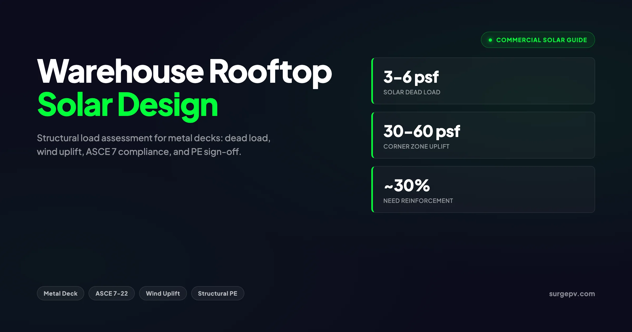
Commercial solar arrays add 3 to 6 psf of dead load to a metal deck, but wind uplift in corner zones can reach 30 to 60 psf, often exceeding dead load by 3 to 5 times. Every project requires a stamped structural letter from a licensed PE confirming the deck, joists, and load paths meet ASCE 7-22 load combinations. About 30 percent of pre-2000 warehouses need reinforcement, typically adding $0.10 to $0.30 per watt to the project budget.
What this guide covers:
- Real load values for panels, racking, ballast, and wiring on warehouse roofs
- How metal deck construction (standing seam, trapezoidal, corrugated) changes the structural calculus
- ASCE 7-22 chapter 29 procedure for rooftop solar wind pressures and the 24-inch live load exemption
- The 6-step structural load assessment workflow used on commercial projects
- Common failure modes specific to warehouse metal decks and how to mitigate them
- Mounting system selection for each deck type
- What the stamped structural letter must contain to clear permit review
Why Warehouse Rooftops Demand a Different Structural Playbook
Warehouse roofs are not residential roofs scaled up. The structural systems are fundamentally different. Most modern warehouses use a roof assembly built on open-web steel joists, supporting a ribbed metal deck with a single-ply membrane (TPO or EPDM) over rigid insulation. The deck thickness is typically 22 gauge to 18 gauge, and joist spacing runs from 4 to 6 feet on center. Spans between primary girders are long, often 40 to 60 feet, which means the structural system has very little reserve capacity for additional loads.
Residential roofs have rafters at 16 or 24 inches on center with sheathing that distributes point loads across multiple framing members. A single solar array footprint touches dozens of rafters. Warehouse roofs concentrate load on a much smaller number of joists, so a 1 MW array on a metal deck can shift 10 to 20 tons of additional dead load onto a system that was never designed to carry it. See Design Commercial Solar System 1MW for detailed guidance.
Three structural realities make warehouse rooftops different:
Long span, low reserve. Open-web steel joists are sized for the original design load with a typical safety factor of 1.5 to 2.0. After 20 years of service and corrosion, real reserve capacity is often closer to 1.1 to 1.3, which leaves very little margin for added solar dead load.
Thin deck, concentrated point loads. A 22-gauge metal deck can deflect noticeably under a 200-pound point load between supporting ribs. Ballasted racking systems concentrate load at tray feet, sometimes producing 8 to 12 psf locally despite an average distributed load of just 4 psf.
Wind-sensitive geometry. Flat warehouse roofs with sharp parapets create aggressive wind acceleration zones at the corners and perimeter. ASCE 7-22 corner zones (zone 3) carry uplift coefficients 2 to 3 times higher than the field of the roof. Solar arrays in those zones need additional ballast, mechanical attachment, or both.
The structural assessment is not a paperwork exercise. It is the single decision point that determines whether the project goes forward, gets de-rated, or dies.
How Much Load Does a Solar Array Actually Add?
The starting point for any structural review is a defensible number for the proposed dead load. Treat it as a sum of panel weight, racking weight, wiring, and ballast (if used). The numbers below reflect typical commercial systems specified in 2025 and 2026.
Panel Weight
Modern bifacial monocrystalline modules in the 540 W to 620 W class weigh 50 to 70 pounds each. With panel dimensions around 90 by 45 inches (28 square feet), the panel-only contribution is roughly 1.8 to 2.5 psf. Read Bifacial Solar Panel Design Guide for a complete walkthrough.
Racking Weight
Aluminum rail-based racking systems for metal decks add 0.5 to 0.8 psf. Steel racking adds 1.0 to 1.5 psf. Rail-less direct-attach systems sit at the lower end, around 0.4 to 0.6 psf.
Wiring, Conduit, and BOS
Conduit, wiring, junction boxes, and rapid shutdown devices add 0.2 to 0.4 psf when distributed across the array footprint. Concentrated loads under combiner boxes and inverters need to be called out separately.
Ballast (if applicable)
For flat-roof ballasted systems, ballast blocks add 4 to 8 psf depending on tilt angle and wind exposure. Higher tilt angles (15 degrees vs 5 degrees) require more ballast to resist uplift, and corner zones need 1.5 to 2 times the field ballast.
Total Dead Load by System Type
| System Type | Panel | Racking | BOS | Ballast | Total Dead Load |
|---|---|---|---|---|---|
| Flush mount on standing seam | 2.0 psf | 0.5 psf | 0.3 psf | 0 | 2.8 psf |
| Flush mount on trapezoidal deck | 2.0 psf | 0.7 psf | 0.3 psf | 0 | 3.0 psf |
| Tilted ballasted (5°) | 2.0 psf | 0.6 psf | 0.3 psf | 4.5 psf | 7.4 psf |
| Tilted ballasted (10°) | 2.0 psf | 0.6 psf | 0.3 psf | 6.0 psf | 8.9 psf |
| Hybrid (mechanical + ballast) | 2.0 psf | 0.7 psf | 0.3 psf | 3.0 psf | 6.0 psf |
The structural engineer needs both the average distributed load and the peak point load. Average is what the joist and girder system carries. Peak point load is what the deck carries between joists. Confuse the two and you get a deck that fails inspection.
For accurate point load calculations on flat-roof projects, the generation and financial tool inside solar design software exports racking layouts with footprint pressures already calculated, which feeds directly into the PE’s review.
Understanding Metal Deck Roof Construction
Metal deck is not a single product. The structural behavior, attachment options, and load capacity vary dramatically by profile. Three profiles dominate warehouse construction in North America and most of Europe. Also see: European Solar Incentives. For Europe-specific compliance details, see Europe solar compliance.
Standing Seam Metal Roof
Standing seam roofs use long metal panels with raised vertical seams that lock together mechanically. The seams typically rise 1.5 to 3 inches above the panel surface, and the spacing between seams runs 12 to 24 inches. The defining feature for solar installations is that the seam itself acts as a structural rail. Clamp-on mounts grip the seam without drilling, which preserves the roof warranty and eliminates leak risk.
Standing seam decks are the easiest substrate for solar from a structural standpoint. The seams transfer load efficiently to the underlying purlins, and clamp-on systems are typically rated for both gravity and uplift loads in published manufacturer data. For more on this attachment method, see our guide on solar panel mounting on standing seam metal roofs.
Trapezoidal (R-Panel) Metal Roof
Trapezoidal profiles have wide flat sections with raised trapezoidal ribs at regular intervals (typically 12 inches on center). The rib crown is the only attachment point with full structural backing, since the wide flats deflect under load. Mounting brackets must land on the rib crown and are usually fastened with self-tapping screws sealed with butyl or EPDM gaskets.
Trapezoidal decks introduce penetration and weatherproofing risk. Every screw is a potential leak path. Mounting density of 1 to 2 brackets per panel is typical, which means a 2 MW warehouse array on trapezoidal deck has 8,000 to 12,000 individual roof penetrations.
Corrugated Metal Roof
Corrugated decks have continuous wave-shaped profiles. They are common on older industrial buildings and small warehouses. Corrugated decks are the most challenging substrate for solar because the curved profile makes both clamping and direct attachment difficult. Specialized brackets that span multiple corrugations are required, and the deck itself often lacks the gauge thickness to carry concentrated solar loads without reinforcement.
Deck Gauge and Span
Beyond profile, two specifications drive structural capacity:
- Deck gauge: thickness of the metal sheet, expressed as gauge number (lower number = thicker). 22 gauge is the minimum for most warehouse applications; 18 gauge is more common on heavy-duty industrial buildings.
- Span: distance between supporting purlins or joists. Spans of 4 to 5 feet are typical for 22-gauge deck; longer spans require thicker deck.
A 22-gauge deck on a 5-foot span has a gravity load capacity of roughly 60 to 80 psf and an uplift capacity of 30 to 50 psf, depending on fastening pattern. Those numbers shrink fast when corrosion or fatigue is present.
Reading ASCE 7 for Solar PV on Metal Decks
ASCE 7 is the governing US standard for minimum design loads on buildings and other structures. Edition matters. ASCE 7-22 is the current cycle and is referenced by IBC 2024. ASCE 7-16 is referenced by IBC 2018 and 2021. The two editions handle solar PV differently in important ways. The ASCE 7 standard entry in our glossary covers the core framework.
Chapter 29: The Solar PV Procedure
ASCE 7-22 chapter 29 contains the wind load calculation procedure specific to rooftop solar PV. The procedure uses the building’s design wind speed, exposure category, and roof zone to compute pressure coefficients (GCp values) that are higher in the corner and perimeter zones than in the field. For a warehouse with 130 mph design wind speed in exposure C, corner zone uplift can reach 50 to 70 psf depending on parapet height and tilt angle.
Three inputs drive the calculation:
- Design wind speed for the project location, taken from ASCE 7 figure 26.5-1.
- Exposure category (B, C, or D) based on surrounding terrain. Most warehouses sit in exposure C.
- Wind exposure zone: zone 1 (field), zone 2 (perimeter), zone 3 (corner). Zone 3 has the highest uplift coefficients.
For a deeper look at how this affects flat-roof ballasted systems, see our analysis on ballasted solar systems and wind uplift. The wind exposure category glossary entry explains how to classify a site.
The 24-Inch Live Load Exemption
ASCE 7-16 introduced a key simplification that ASCE 7-22 retained. If the entire solar array sits no more than 24 inches above a low-slope roof surface, the area beneath the panels does not require roof live load to be applied. This recognizes that maintenance personnel cannot walk under the panels, so the 20 psf roof live load does not stack on top of the solar dead load.
The exemption fails the moment any portion of the system rises above 24 inches. Tilt-mounted ballasted systems at 10 degrees on a 1.5-meter panel rise to roughly 26 to 28 inches, which kicks the roof live load back into the calculation. This is one of the most common drivers of late-stage structural deficiencies on warehouse projects.
Load Combinations
ASCE 7 specifies the load combinations the design must satisfy. The governing combinations for rooftop solar on a warehouse metal deck are:
- 1.4D
- 1.2D + 1.6L + 0.5(Lr or S or R)
- 1.2D + 1.0W + L + 0.5(Lr or S or R)
- 0.9D + 1.0W
Where:
- D = dead load (panels + racking + wiring + ballast)
- L = live load
- Lr = roof live load
- S = snow load
- W = wind load (positive for downward, negative for uplift)
- R = rain load
The 0.9D + 1.0W combination is the uplift check. If the building’s net dead load (existing roof dead load plus new solar dead load, factored at 0.9) cannot resist the wind uplift force, the system needs additional ballast or mechanical attachment.
Snow Load Triangle
ASCE 7-22 chapter 7 governs snow load. Solar panels on a warehouse roof create snow drift zones at the panel edges, which can produce localized snow loads of 1.5 to 2 times the ground snow load. The snow load calculation glossary entry covers the basics. In northern climates, the drift zone often controls the structural capacity of the joists immediately under the perimeter rows, which is why those joists frequently need reinforcement on retrofit projects.
The Structural Load Assessment Workflow
A repeatable, defensible workflow turns the structural review from a project-killing surprise into a routine 3 to 4 week task. The process below is the one used on commercial warehouse projects across North America.
Step 1: Collect Existing Structural Drawings
Before any design work, request the original architectural and structural drawings from the building owner. The drawings provide:
- Joist schedule with size, spacing, and span
- Metal deck specification (gauge, profile, span direction)
- Column grid and primary girder layout
- Original design loads (dead, live, snow, wind)
If drawings are missing, the project needs a structural site survey before feasibility can advance. Surveys cost $5,000 to $15,000 for a typical 100,000 to 250,000 square foot warehouse.
Step 2: Conduct the Rooftop Site Survey
The survey documents what was built, not what was specified. Key data points:
- Deck gauge (measured with a thickness gauge or ultrasonic thickness meter)
- Rib profile and rib spacing
- Joist depth, top chord size, web member sizing
- Joist spacing and span
- Existing penetrations, mechanical equipment, parapets, screens
- Visible deflection, corrosion, water damage
- Membrane condition and roof age
A drone survey captures a high-resolution roof image used for array layout in solar design software like SurgePV, while a ground-truth visit verifies structural details that aerial imagery cannot resolve. For a direct comparison, see Arka 360 vs SurgePV.
Step 3: Calculate the Proposed Solar Dead Load
Convert the array layout into structural inputs:
- Distributed dead load (psf) across the array footprint
- Point loads at each support foot or ballast tray
- Concentrated loads under combiner boxes, inverters, and DC optimizers
- Cable tray loads (if applicable)
The output should be a heat map of point loads overlaid on the joist plan. This map drives the next step.
Step 4: Run ASCE 7 Load Combinations
The structural engineer applies the governing ASCE 7 load combinations to each joist, deck panel, and column under the array. The output is a utilization ratio for each member: actual load divided by allowable capacity. Members above 1.0 are deficient and need reinforcement.
This is where commercial-grade load analysis software earns its keep. Manual calculations on a 2 MW array with 200+ joists take days. Automated tools run the same analysis in minutes and flag every deficient member with a stamped report ready for PE review.
Step 5: Identify Deficient Zones and Mitigation
Deficient members fall into one of three categories:
- Joist deficiency: usually solved with sister joists welded to the existing chord, adding 20 to 40 percent capacity per joist
- Deck deficiency: solved with deck overlay (bonding new metal deck or plywood over the existing deck), or by re-locating the array to landed on rib crowns
- Girder/column deficiency: rare but expensive, requiring column reinforcement or load redistribution to other framing lines
The cost of mitigation is the project’s primary economic risk. Light reinforcement adds $0.05 to $0.15 per watt. Heavy reinforcement (sister joists across most of the roof) adds $0.20 to $0.40 per watt and can push the project past its IRR threshold.
Step 6: Issue the Stamped Structural Letter
The licensed Professional Engineer reviews calculations, signs and stamps the structural letter, and submits it as part of the permit package. The letter is a hard prerequisite in every US jurisdiction, and most international jurisdictions have an equivalent requirement (chartered engineer letter in the UK, prufstatiker in Germany, ingegnere strutturista in Italy). Also see: solar panel ROI in Italy. Also see: Germany solar subsidies.
Run the Structural Layout in 20 Minutes
SurgePV exports racking layouts, point loads, and ballast plans your structural engineer needs in one workflow. No more spreadsheet handoffs.
Book a DemoNo commitment required · 20 minutes · Live commercial project walkthrough
Common Failure Modes on Warehouse Metal Decks
A pattern emerges after running the structural assessment on a few hundred commercial projects. Failures cluster around six specific issues, and recognizing them early in the feasibility phase saves weeks of rework.
Open-Web Steel Joist Capacity
Open-web joists (OWSJ) carry the bulk of the gravity load on a warehouse roof. They were sized for the original design load, with reserve capacity that depends on the era of construction. Joists from the 1970s and 1980s often have just 10 to 20 percent reserve, which is below what a typical 4 to 6 psf solar dead load demands. Modern joists (2000 onward) usually have 30 to 50 percent reserve, which is enough for most flush-mount systems but tight for ballasted designs.
The fix is sister joists or new joists added between the existing ones. Both options are messy on a roof with an existing membrane. They require cutting the membrane, welding inside the building, and re-flashing the penetrations.
Deck Gauge Below Specification
Field measurement frequently shows deck thickness 1 to 2 gauges thinner than the original drawings. Corrosion accounts for some of it, especially in coastal or humid environments. Substitution during original construction accounts for the rest, the contractor used a thinner deck than specified to save cost.
A 22-gauge deck downgraded to 24 gauge over 30 years drops uplift capacity by 30 to 40 percent. Solar arrays in corner zones are the first to fail this check.
Concentrated Point Loads Under Ballast Trays
Ballast trays concentrate load on a few small footprints. A typical tray with 600 pounds of ballast on a 4 square foot footprint produces 150 psf of point load, which is well above the 60 to 80 psf gravity capacity of a 22-gauge deck on a 5-foot span. The tray must land directly over a joist, not in the field of the deck.
This is why ballasted designs always include a layout overlay showing tray feet centered over joists. Miss this and the deck buckles under load.
Wind Uplift in Corner Zones
ASCE 7 zone 3 (corners) carries uplift pressures 2 to 3 times higher than the field of the roof. On a warehouse with a 30-foot height and a 130 mph design wind, corner uplift can hit 60 to 80 psf. A flush-mount array in zone 3 needs additional mechanical attachment, and a ballasted array needs roughly 2x the ballast of a field-zone array.
Snow Drift at Panel Edges
In climates with ground snow load above 30 psf, snow drift zones at the upwind edge of solar panels can produce localized snow loads of 50 to 80 psf. The joists immediately under those zones routinely fail the structural check, even when the field of the roof is fine. Reinforcement is targeted to the perimeter, not the entire array.
Mechanical Equipment Conflicts
Existing rooftop mechanical units (RTUs), exhaust fans, and skylights create no-go zones for solar. The structural impact comes when the array is forced into a pattern that concentrates load on a few joists rather than distributing it across the roof. The solution is array layout iteration in solar proposal software and design tools, not on a napkin.
Choosing the Right Mounting System for Metal Decks
Mounting system selection is a structural decision before it is a cost decision. The right system depends on deck type, deck gauge, slope, wind zone, and the building’s ballast tolerance.
Standing Seam: Clamp-On Systems
Clamp-on mounts grip the standing seam fold and transfer load through the seam to the underlying purlins. Industry-standard clamps include S-5! S-5-S, AceClamp, and similar UL-listed products. They are rated for both gravity and uplift loads in published manufacturer data, with typical capacities of 500 to 1,500 pounds per clamp.
Advantages: zero penetrations, preserved roof warranty, fast installation (1 to 2 minutes per clamp).
Disadvantages: higher unit cost ($15 to $30 per clamp), only compatible with mechanically locked seams, not snap-lock profiles below a certain depth.
Trapezoidal Deck: Direct-Attach with Sealed Penetrations
Trapezoidal decks accept brackets fastened with self-tapping screws into the rib crown. Brackets typically use a butyl gasket or EPDM washer to seal the penetration. Common products include the IronRidge XR Rail, Unirac SunFrame, and S-5! ProteaBracket.
Bracket spacing is dictated by the ASCE 7 wind load calculation, not by panel length. In zone 3 corners, brackets may be required every 4 feet, while zone 1 field areas allow 6-foot spacing.
Corrugated Deck: Spanning Brackets
Corrugated decks need spanning brackets that bridge multiple corrugations and transfer load to the underlying purlins. Specialized products like the Roof Tech RT-Mini and Quick Mount PV W Bracket handle this profile, but the unit cost and installation time are both higher than trapezoidal direct-attach.
Flat Low-Slope Roofs: Ballasted vs Hybrid
Flat low-slope warehouse roofs (slope below 7 degrees) accept ballasted systems if the deck and joists can carry the point load. The trade-off is dead load: a ballasted system at 6 to 8 psf is 3x heavier than a flush-mount system at 2.5 to 3 psf.
Hybrid systems combine mechanical attachment and ballast. The mechanical anchors handle uplift, ballast handles gravity stability. Hybrid is the right call when the roof can carry 4 to 5 psf but not 7 to 8 psf, which is common on 1990s and 2000s warehouses.
The choice between ballasted racking and a hybrid attachment system is one of the most consequential structural decisions on the project.
Wind Uplift, Snow, and Seismic Considerations
Beyond the basic dead load check, three environmental loads drive the structural design on warehouse rooftops.
Wind Uplift
Wind uplift is almost always the controlling load on flat-roof solar arrays. The ASCE 7-22 chapter 29 procedure produces zone-specific pressure coefficients that vary with parapet height, building height, and array tilt angle. A few patterns repeat:
- Higher parapets reduce wind acceleration over the roof, lowering uplift coefficients in corner zones by 15 to 25 percent
- Lower tilt angles (5 degrees vs 10 degrees) reduce uplift pressure by 20 to 30 percent
- Wider panel-to-panel gaps increase wind penetration into the array, raising uplift on adjacent panels
The wind load calculation glossary entry covers the calculation framework. The practical lesson: a 10-degree ballasted array in a 130 mph zone will need 1.5x to 2x more ballast than the same array at 5 degrees.
Snow Load
In northern US states, Canada, and northern Europe, snow load can exceed wind load as the controlling case. ASCE 7-22 chapter 7 governs the calculation, with two regimes: For Canada-specific compliance details, see Canada comparisons/solar-design-software.
- Balanced snow load: uniform snow accumulation across the roof
- Drifted snow load: localized accumulation at obstructions, including solar panel arrays
Drifted snow at the upwind edge of an array can reach 1.5 to 2x the balanced load. The drift zone extends roughly 4 to 8 panel widths into the array before tapering. Joists in the drift zone often need reinforcement.
Seismic
In seismic zones (US west coast, parts of Italy, Japan, New Zealand), ASCE 7 chapter 13 governs nonstructural component seismic design. Solar arrays qualify as nonstructural components, and ballasted arrays in particular need a sliding analysis to confirm they will not migrate during a design-level earthquake. For the latest details on Italy, see Commercial Rooftop Solar Case Study Italy. See our guide on Italy Solar Feed-in Tariffs for more.
The seismic check usually does not control the design in moderate seismic zones (most of the US east of the Rockies, most of central Europe). It controls almost every project in California, Oregon, Washington, Italy, and Japan. For the latest details on Italy, see Italy Superbonus Solar.
When the Structural Engineer Says No: Mitigation Options
About one in three warehouse projects fails the initial structural check. The PE letter does not have to mean project death. Five mitigation paths recover most failed projects.
Path 1: Reduce Array Size
The simplest fix. De-rate the array to fit within the roof’s existing capacity. A warehouse that fails at 2 MW often passes at 1.5 MW, especially if the failure is in corner zones or under specific joists. Compute the IRR on the smaller system and decide whether the project still clears the financial threshold.
Path 2: Re-Layout to Avoid Deficient Zones
Move panels off failing joists. This works when the failures are localized rather than systemic. Layout iteration in solar design platform can produce 5 to 10 alternatives in an hour, which is faster than waiting on the structural engineer to recalculate each one manually.
Path 3: Switch from Ballasted to Mechanically Attached
Ballasted systems double or triple the dead load. If a ballasted design fails, a mechanically attached design often passes because the dead load drops to 2.5 to 3 psf. The trade-off is roof penetrations, which carry warranty and waterproofing risk on older membranes.
Path 4: Reinforce Specific Joists
Sister joists or new joists added between existing members add 20 to 40 percent capacity per joist. Targeted reinforcement under high-load zones (corners, perimeter, inverter pad locations) is often more cost-effective than reinforcing the entire roof.
Path 5: Roof Replacement Tied to Solar
If the membrane is at end of life and the deck is borderline, the economics of replacing both at once often beat doing them separately. New deck and membrane installation can include upgraded gauge specifically to support solar, eliminating the structural deficit while extending roof service life by 20+ years.
The decision tree is project-specific. A C-suite financial analysis using a generation and financial tool reveals which path delivers acceptable IRR. The wrong call here costs $50,000 to $500,000.
Documentation: What the Structural Letter Must Contain
The stamped structural letter is the deliverable that closes out the structural review. AHJs reject letters that lack specific elements. A complete letter contains:
- Project identification: site address, building owner, array size in kW DC and panel count
- Existing structure description: deck gauge and profile, joist schedule, primary girder layout, column grid
- Existing roof loads: original design dead, live, snow, and wind loads from the building drawings or the survey
- Proposed solar loads: distributed dead load (psf), peak point loads (lbs), wind uplift forces by zone
- Code references: applicable IBC edition, ASCE 7 edition, local amendments
- Load combinations applied: explicit list of governing combinations with results
- Member-by-member capacity check: utilization ratios for joists, deck panels, girders, columns
- Reinforcement specifications (if required): location, sizing, and connection details
- PE stamp and signature: licensed in the project jurisdiction
- Date of issuance: usually valid for 12 to 24 months before re-review
A complete letter clears permit review on the first submittal. An incomplete letter triggers an RFI that adds 2 to 4 weeks to the project schedule. Buy the extra hour of PE time upfront.
Conclusion: Action Items for Warehouse Solar Projects
- Pull existing structural drawings during the very first feasibility call. If drawings are unavailable, budget $5,000 to $15,000 and 2 to 3 weeks for a structural site survey before any design work begins.
- Specify the dead load and point load profile of the proposed array in the structural engineer’s brief. Give them the layout, the mounting system, and the ballast plan upfront so they run the load combinations against the actual design, not a placeholder.
- Reserve 25 to 30 percent of the structural budget as contingency for reinforcement. Pre-2000 warehouses fail at this rate and the fix is rarely zero-cost.
Frequently Asked Questions
How much weight does a rooftop solar system add to a warehouse metal deck?
A typical flush-mount commercial solar system adds 3 to 5 pounds per square foot (psf) of dead load. Ballasted systems on flat warehouse roofs add 4 to 6 psf, with localized point loads under each ballast tray reaching 8 to 12 psf. The structural engineer must verify both distributed load and point load capacity of the metal deck and supporting joists.
Do metal deck warehouse roofs need a full structural engineering review for solar?
Yes. Every commercial solar project on a metal deck requires a stamped structural letter from a licensed Professional Engineer in the project jurisdiction. The letter confirms the existing roof structure can carry the additional dead load, wind uplift, and snow load combinations under ASCE 7 or the local equivalent code.
What is the maximum wind uplift force on a warehouse rooftop solar array?
Wind uplift on flat warehouse roofs in high-exposure zones can reach 30 to 60 psf at corner zones, often exceeding the dead load by a factor of 3 to 5. ASCE 7-22 requires designers to use the chapter 29 procedure for rooftop solar to calculate zone-specific pressures, with the perimeter and corner zones carrying the highest uplift coefficients.
Can you install solar on a warehouse without penetrating the metal deck?
Standing seam metal roofs accept clamp-on mounts that grip the seam without drilling, which is the preferred non-penetrating option. Trapezoidal and corrugated metal decks usually require self-tapping screws into the rib crown, with butyl or EPDM gaskets to seal the penetration. Ballasted systems are an option only on low-slope decks with verified point load capacity.
What is the typical structural deficit found during warehouse solar feasibility?
Roughly 25 to 35 percent of older warehouses (pre-2000) fail the initial structural assessment due to undersized open-web steel joists or thin metal deck gauges. The most common fix is adding sister joists or reinforcing the deck under high-load zones, which adds $0.10 to $0.30 per watt to the project cost.
Does ASCE 7 require live load on the area covered by solar panels?
ASCE 7-16 and ASCE 7-22 do not require roof live load on areas covered by solar panels when the entire array sits no more than 24 inches above a low-slope roof. If any portion of the system rises above 24 inches, that portion must be designed for the full roof live load in addition to the solar dead load.
How long does a structural load assessment take for a warehouse solar project?
A standard structural assessment for a 200 kW to 1 MW warehouse rooftop project takes 2 to 4 weeks from site visit to stamped letter. This includes the field survey, deck and joist measurement, calculation runs against ASCE 7 load combinations, and PE review. Older buildings without original drawings can extend the timeline by 2 to 3 weeks.
What software is used to design warehouse rooftop solar systems?
Commercial solar designers use cloud platforms like SurgePV that combine roof imagery, automated array layout, shading analysis, and structural load reporting in one workflow. The software exports panel weight per square foot, ballast point loads, and racking layouts that feed directly into the structural engineer’s review. Shadow analysis software identifies shading issues before installation.