

A 40A solar backfeed breaker on a 200A main panel is one of the most common sizing decisions in residential solar. It is also one of the most frequently wrong. The breaker might be sized to the inverter kW rating instead of its continuous output current. It might ignore the 120% busbar rule. Or it might be an AC-rated device dropped into a DC combiner box. Any of those errors produces a plan-check correction, a failed inspection, or worse — an undersized conductor that overheats before the breaker trips.
Solar breaker sizing covers four distinct locations: the DC string or source-circuit breaker, the DC combiner output breaker, the AC inverter output breaker, and the main panel backfeed breaker. Each has its own NEC article, multiplier, and failure mode. This guide walks through each location with the exact formulas from NEC 690.8, 690.9, and 705.12, plus worked examples for a 7.6 kW residential system and a 250 kW commercial system.
Quick Answer — Solar Breaker Sizing
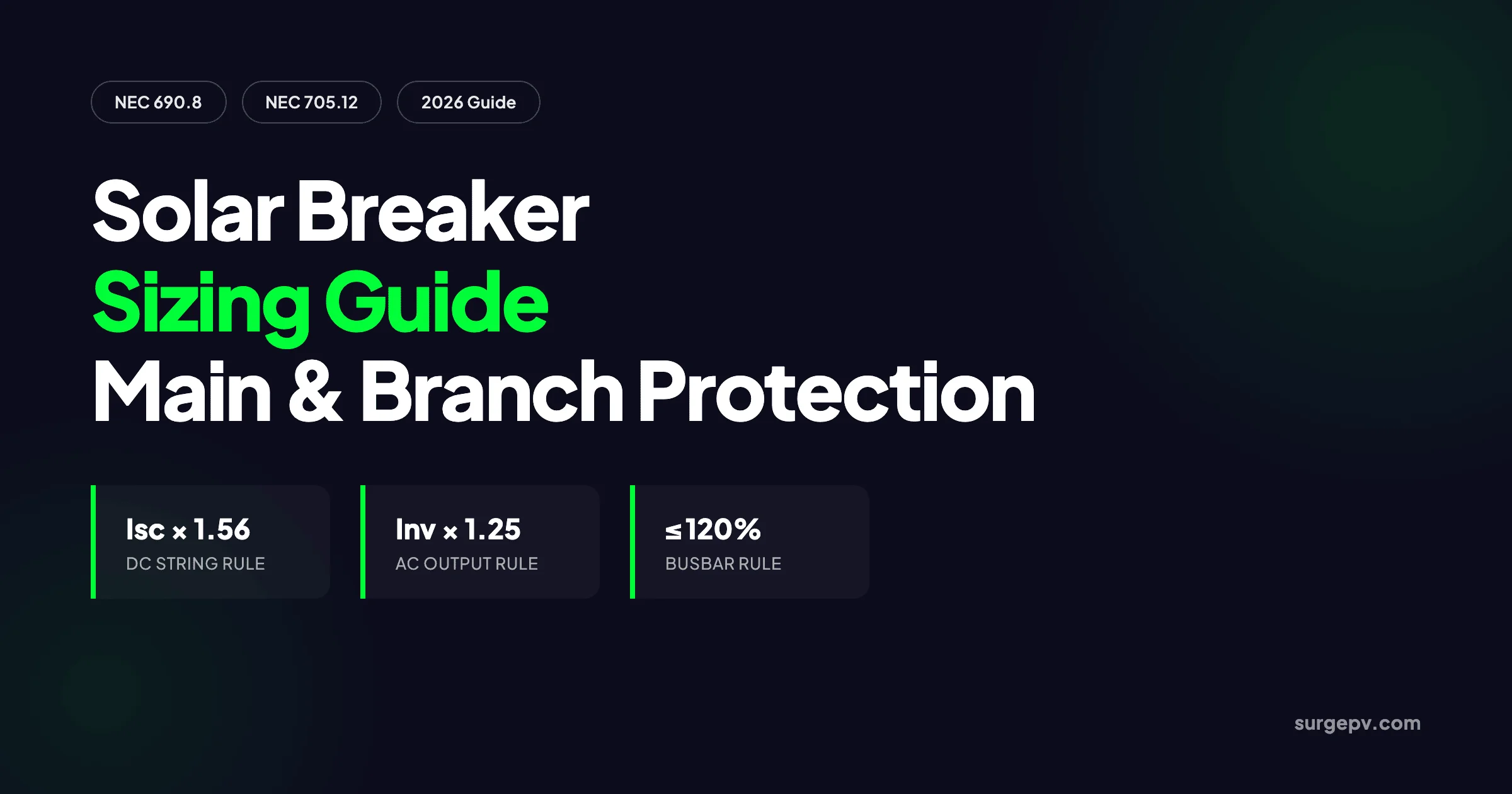
Solar breaker sizing depends on circuit location. DC source circuits use Isc × 1.56. AC inverter output circuits use inverter max continuous output current × 1.25. Main panel backfeed breakers must satisfy the 120% rule: main breaker + PV breaker ≤ 1.20 × busbar rating. Every breaker must be listed for its voltage, current, and AC or DC application.
In this guide:
- The four breaker locations in a PV system and the NEC article that governs each
- How to size DC string breakers and fuses using the 1.56 multiplier
- How to size AC inverter output breakers using the 1.25 multiplier
- The 120% busbar rule and when to derate the main breaker
- Main breaker sizing for new solar-ready services
- Breaker vs fuse tradeoffs for each circuit location
- The ten most common breaker sizing mistakes that fail inspection
- How solar design software automates breaker selection on the SLD
The Four Breaker Locations in a PV System
Every grid-tied PV system has at least three overcurrent protection device (OCPD) locations. Large commercial systems add a fourth. Knowing which article applies at each location is the first step to sizing correctly.
| Location | NEC Article | Multiplier | Typical Device |
|---|---|---|---|
| PV source circuit (string) | 690.8(A)(1), 690.9 | Isc × 1.56 | gPV fuse or DC-rated breaker |
| PV output circuit (combiner to inverter) | 690.8(A)(2), 690.9 | Sum of source currents × 1.25 | DC-rated breaker or fused disconnect |
| Inverter AC output circuit | 690.8(A)(3), 705.30 | Inverter max continuous current × 1.25 | AC breaker |
| Main panel backfeed breaker | 705.12(B)(2) | 120% of busbar minus main breaker | AC backfed breaker |
The first two locations are on the DC side. The third and fourth are on the AC side. The rules are not interchangeable. A breaker rated for 600V AC cannot interrupt a 600V DC arc, and a fuse sized for module Isc is too small for an inverter output circuit.
Why Location Matters More Than Amperage
A breaker is not just a breaker. Its voltage rating, interrupting rating, and listing determine where it can be installed. DC-rated molded-case breakers use arc chutes and magnetic blowout coils to stretch and cool the arc until it extinguishes. AC breakers rely on the current crossing zero naturally 120 times per second at 60 Hz. Installing an AC-only breaker in a DC circuit violates NEC 110.3(B) and can fail catastrophically under load.
The same discipline applies to interrupting rating. A residential main panel breaker might see 10 kA of available fault current from the utility. A DC combiner breaker might see only 1.5 kA because PV fault current is irradiance-limited. Both ratings must be checked, but the numbers come from different sources.
DC Branch Circuit Breaker Sizing: The 1.56 Multiplier
PV source circuits are the conductors between the module string and the combiner box or inverter input. Because their current is driven by sunlight, not by a rotating machine or utility transformer, they need a special sizing rule.
NEC 690.8(A)(1) sets the maximum circuit current at 125% of module Isc. NEC 690.8(B)(1) then requires conductors and overcurrent devices sized at 125% of that current. Combined, the minimum OCPD rating is:
Minimum OCPD rating = Isc × 1.25 × 1.25 = Isc × 1.56The first 1.25 accounts for irradiance above Standard Test Conditions of 1,000 W/m². The second 1.25 accounts for continuous operation — a PV string produces current for more than three hours at a stretch on most sunny days.
After applying 1.56, round up to the next standard size per NEC 240.6(A). Standard sizes include 15, 20, 25, 30, 35, 40, 45, 50, 60, 70, 80, 90, 100A, and larger. GEYA’s breaker sizing guide summarizes the same residential calculation for homeowners and installers.
String Fuse Ceiling: Maximum Series Fuse Rating
The OCPD cannot be larger than the module manufacturer’s maximum series fuse rating. This value is printed on the module nameplate. If the 1.56 calculation gives 25A but the module is only rated for 20A, the design must change — either use a different module, split strings across more MPPT inputs, or accept the smaller OCPD and verify the conductor still passes.
Worked Example: DC String Breaker Sizing
Module data:
- Isc = 10.18 A
- Maximum series fuse rating = 20 A
- Maximum system voltage = 1,000 V DC
Calculation:
10.18 A × 1.56 = 15.88 ARound up to the next standard size: 20 A. The 20A fuse also satisfies the module’s maximum series fuse rating of 20A. A 15A fuse would be below the minimum required by NEC 690.9. A 25A fuse would exceed the module rating.
When String-Level OCPD Is Not Required
NEC 690.9(A) allows omitting OCPD where the conductor is already protected against overcurrent. In practice, this applies when there is no backfeed path. For a single string per MPPT, there is no parallel source to feed a fault. For two strings in parallel, the maximum backfeed into a faulted string is one string’s Isc, which is normally below the conductor ampacity. For three or more parallel strings, string-level fuses or breakers are required because the combined backfeed from the healthy strings can overheat the faulted string’s conductor.
PV Output Circuit Breaker Sizing: Combiner to Inverter
The PV output circuit carries the combined current of all parallel strings. Its OCPD protects the conductor between the combiner box and the inverter input.
NEC 690.8(A)(2) sets the maximum current as the sum of parallel source circuit currents. NEC 690.8(B)(1) applies the same 1.25 continuous-load multiplier. Because the source-circuit currents are already multiplied by 1.25 under 690.8(A)(1), the output-circuit multiplier is 1.25, not 1.56.
Minimum output OCPD = (number of strings × Isc × 1.25) × 1.25
                    = number of strings × Isc × 1.5625
Round up to the next standard size. The device must be DC-rated for the maximum system voltage and the available DC fault current.
Worked Example: Combiner Output Breaker
System: 10 strings, each with Isc = 10.18 A
Maximum circuit current = 10 × 10.18 A × 1.25 = 127.25 A
Minimum OCPD rating = 127.25 A × 1.25 = 159.06 A
Round up to the next standard size: 160 A DC-rated breaker or fuse. Verify the conductor ampacity after temperature and conduit derating is at least 160A. If the conductor runs through rooftop conduit in a hot climate, the required conductor size may be much larger than the base calculation suggests.
For the full conductor sizing procedure, see the solar wire sizing guide.
AC Inverter Output Breaker Sizing: The 1.25 Multiplier
The inverter output circuit is different from a PV source circuit because the current is limited by electronics, not by sunlight. NEC 690.8(A)(3) sets the maximum current at the inverter’s rated continuous output current. NEC 705.30 then requires the OCPD to be sized at 125% of that current.
Minimum inverter output breaker = inverter max continuous AC output current × 1.25Use the inverter’s rated maximum continuous output current from the datasheet — not the peak power rating divided by voltage. Modern inverters specify this value directly, often labeled “Max AC output current” or “Rated output current.” SMA publishes a concise worked example for sizing a PV inverter breaker at 125% of rated output current, which remains a reliable field reference.
Worked Example: 7.6 kW Residential Inverter
Inverter data:
- Rated max continuous AC output current = 31.7 A
- AC voltage = 240 V, single-phase
31.7 A × 1.25 = 39.63 ARound up to the next standard size: 40 A. This is the same breaker size commonly used as the solar backfeed breaker in a 200A main panel under the 120% rule.
Worked Example: 250 kW Commercial Inverter
Inverter data:
- Rated max continuous AC output current = 301 A
- AC voltage = 480 V, three-phase
301 A × 1.25 = 376.25 ARound up to the next standard size: 400 A. A 400A breaker at 480V three-phase protects the inverter-to-switchgear conductor and satisfies NEC 705.30. The conductor must be sized for at least 400A after all derating factors.
Main Panel Backfeed and the 120% Rule
The solar backfeed breaker connects the inverter output to the main service panel. Its size is limited by two rules: it must be at least 125% of the inverter output current, and it must satisfy the 120% busbar rule.
NEC 705.12(B)(2) states:
Main breaker rating + PV backfeed breaker rating ≤ 1.20 × busbar ratingThe PV breaker must also be placed at the opposite end of the busbar from the main breaker, with a permanent label that reads “DO NOT RELOCATE THIS OVERCURRENT DEVICE.” That placement is what makes the 20% allowance thermally safe — loads tap off between the two sources, so no single bus segment carries both full feeds at once. NEC 2026 clarifies that the 120% figure applies to the supply-side busbar rating, not the main breaker size, closing a common AHJ interpretation gap. For a deeper look at busbar calculations, see the busbar calculator guide or use the SurgePV busbar size calculator.
Worked Example: Standard 200A Residential Panel
Panel data:
- Busbar rating = 200 A
- Main breaker = 200 A
Maximum PV backfeed breaker = (200 A × 1.20) − 200 A = 40 AA 40A backfeed breaker supports a continuous inverter output of:
40 A ÷ 1.25 = 32 A
32 A × 240 V = 7.68 kW AC
That is why a 7.6 kW inverter and a 40A backfeed breaker are a common residential pairing. Greenlancer’s guide to the 120% rule explains the opposite-end placement and “DO NOT RELOCATE” label requirements in more detail.
Worked Example: 225A Busbar with 200A Main
Some panels ship with a 225A busbar and a 200A main breaker. That combination is popular for solar because it creates more headroom:
(225 A × 1.20) − 200 A = 70 AA 70A backfeed breaker supports up to 13.4 kW AC output at 240V. This is the configuration many “solar-ready” loadcenters use.
What If the System Needs More Than the 120% Rule Allows?
Three common solutions exist when the 120% rule limits system size:
- Derate the main breaker. Replace a 200A main with a 175A main. The calculation becomes (200 × 1.20) − 175 = 65A of solar backfeed. This only works if the existing loads do not exceed 175A. A load calculation per NEC 220 is required. Wattmonk’s NEC 705.12 guide walks through derating examples for installers.
- Use a supply-side connection. Connect the solar output ahead of the main breaker, typically at the meter-main or service conductors. The 120% rule does not apply, but the connection must be engineered and approved by the utility.
- Install an Energy Management System (EMS). NEC 705.13 permits an EMS to limit inverter output current dynamically, allowing a larger system on a smaller busbar. The EMS must be listed and configured to never exceed the programmed limit.
Main Breaker Sizing for New Solar-Ready Services
For new construction or service upgrades, the main breaker is sized to the service rating and the load calculation. The solar backfeed breaker is then sized within the 120% rule or through an EMS.
For commercial projects, a supply-side connection is often the cleaner path once the load-side 120% limit is reached. The commercial solar design guide covers interconnection sizing for larger systems.
A 400A service with a 400A busbar and a 400A main breaker allows:
(400 A × 1.20) − 400 A = 80 AAn 80A backfeed breaker supports 19.2 kW AC at 240V. For larger commercial systems, a supply-side connection is usually more economical than upsizing the entire service.
When specifying a solar-ready panel, choose a busbar rating at least equal to the main breaker rating. Some panels have a 200A main with a 225A busbar specifically to create the extra 25A of solar headroom without a full service upgrade.
Breaker vs Fuse: When Each Wins
Both devices protect against overcurrent, but their behavior differs. The right choice depends on the circuit location and maintenance needs.
| Factor | Fuse | Circuit Breaker |
|---|---|---|
| Cost | Lower | Higher |
| Reset after trip | No — must replace | Yes — reset or replace if damaged |
| Current-limiting performance | Excellent with gPV fuses | Good if DC-rated and current-limiting |
| Disconnect function | Requires separate switch if isolation needed | Often built-in |
| Maintenance access | Less convenient | More convenient |
| Best location | String level in combiner boxes | Inverter AC output, main panel backfeed |
Many designers use fuses at the string level because gPV fuses are tested specifically for PV DC fault conditions and have predictable melting characteristics. Breakers are preferred where frequent switching or reset is expected, such as the inverter AC output or a disconnecting combiner. Remember that a breaker sized for overcurrent protection is not always the same device as the disconnect required by NEC 690.15 — the AC disconnect sizing guide covers the equipment-isolation rules separately. For systems with multiple inverter levels, the discipline of matching each OCPD to the fault location is called selective coordination — covered in the overcurrent protection coordination guide.
Common Sizing Mistakes That Fail Inspection
The same errors show up repeatedly on permit corrections. Most are avoidable with a checklist.
| Mistake | Why It Fails | Fix |
|---|---|---|
| Using inverter kW ÷ voltage instead of rated output current | Misses power factor and manufacturer derating | Use datasheet max continuous AC output current |
| Skipping the 1.25 continuous load multiplier on AC output | Breaker undersized; nuisance trips or conductor overheating | Multiply inverter output current by 1.25 |
| Applying 1.56 to inverter output current | Overstates required breaker size | 1.56 is for DC source circuits only |
| Using an AC breaker in a DC circuit | DC arc will not clear; fire hazard | Use DC-rated breaker or gPV fuse |
| Ignoring the 120% busbar rule | Panel busbar can overheat | Check main + PV breaker ≤ 1.20 × busbar |
| Wrong breaker placement in panel | Loses the thermal benefit of opposite-end rule | Place PV breaker at opposite end from main; add label |
| Exceeding module maximum series fuse rating | Module warranty void; conductor under-protected | Use OCPD ≤ module nameplate maximum fuse rating |
| Forgetting temperature derating on conductors | Wire ampacity drops in hot conduit | Run NEC 690.8(B)(2) and upsize if needed |
| Selecting breaker before conductor | Breaker can allow more current than wire can carry | Size conductor first, then breaker |
| Omitting the “DO NOT RELOCATE” label | AHJ rejects because future moves defeat the 120% rule | Add permanent label at installation |
How Solar Design Software Handles Breaker Sizing in 2026
Manual breaker sizing on a complex permit set involves four separate calculations, multiple datasheet lookups, and a cross-check against the panelboard schedule. Solar design software automates this by linking each device to its manufacturer datasheet.
When you select an inverter in SurgePV, the platform reads the rated maximum continuous AC output current and applies the 1.25 multiplier. It checks the result against the 120% busbar rule using the panel rating you entered. If the inverter needs a 50A breaker but the panel only allows 40A, the software flags the conflict before the permit is submitted.
For the DC side, the software pulls module Isc and maximum series fuse rating, applies the 1.56 multiplier, and recommends a standard OCPD size. It also flags whether string-level protection is required based on the parallel string count.
The breaker and fuse ratings flow directly into the single-line diagram and the bill of materials. The device the AHJ sees on the drawing is the same device ordered for the job. That consistency eliminates the mismatch errors that cause resubmits.
Conclusion
Solar breaker sizing is four calculations, not one. Each circuit location — DC string, DC combiner output, AC inverter output, and main panel backfeed — uses a different NEC rule and multiplier.
- DC source circuits: Isc × 1.56, not to exceed the module’s maximum series fuse rating
- DC output circuits: sum of source currents × 1.25 × 1.25, rounded up
- AC inverter output: rated max continuous current × 1.25, rounded up
- Main panel backfeed: main breaker + PV breaker ≤ 1.20 × busbar rating, opposite-end placement required
Get these four right and you eliminate most breaker-related inspection failures. Use DC-rated devices on DC circuits, AC-rated devices on AC circuits, and size the conductor to match the breaker under actual installation conditions. For multi-inverter or complex interconnection projects, solar design software that applies the rules automatically saves time and catches conflicts before the AHJ does.
Frequently Asked Questions
How do you size a breaker for a solar inverter output circuit?
Multiply the inverter’s maximum continuous AC output current by 1.25 per NEC 690.8(A)(3). Round up to the next standard breaker size per NEC 240.6(A). For a 7.6 kW inverter at 240V with 31.7A output, the minimum breaker is 40A. The conductor must be sized to match the breaker ampacity after temperature and conduit derating.
What size breaker do I need for a single solar string?
For DC source-circuit protection, multiply the module short-circuit current (Isc) by 1.56 per NEC 690.8(A)(1) and 690.9. Round up to the next standard fuse or breaker size, but never exceed the module’s maximum series fuse rating on the nameplate. A module with 10.5A Isc needs a 20A OCPD minimum (10.5 × 1.56 = 16.38A → 20A).
What is the 120% rule for solar backfeed breakers?
NEC 705.12(B)(2) says the sum of the main breaker rating and the solar backfeed breaker rating cannot exceed 120% of the panelboard busbar rating when the PV breaker is at the opposite end of the bus from the main breaker. A 200A busbar with a 200A main allows a 40A solar backfeed breaker: (200 × 1.20) − 200 = 40A.
Can I use a standard AC breaker in a DC solar circuit?
No. DC arcs do not self-extinguish at zero crossing like AC arcs. A breaker used in a DC PV circuit must be listed for DC service, with voltage and interrupting ratings that meet or exceed the maximum system voltage and available fault current. Look for UL 489B or equivalent DC ratings.
When can I omit string-level fuses or breakers in a PV array?
NEC 690.9(A) allows omitting string-level OCPD when there is no backfeed path that can damage the conductor. This usually means a single string per maximum power point tracker (MPPT). For two strings in parallel, backfeed from one healthy string into a faulted string equals one string’s Isc, so fusing is typically still not required. For three or more parallel strings, string-level OCPD is required.
What is the difference between breaker sizing for DC and AC solar circuits?
DC source circuits use a 1.56 multiplier on module Isc (1.25 for irradiance × 1.25 for continuous load). AC inverter output circuits use a 1.25 multiplier on the inverter’s rated maximum continuous output current. DC breakers must be DC-rated; AC breakers can serve on the inverter output if listed for the voltage and current.
How do I size a main breaker for a new solar-ready panel?
Size the main breaker to the service rating and load calculation per NEC 220. The solar backfeed breaker is then limited by the 120% busbar rule or by an Energy Management System under NEC 705.13. For a 400A service with a 400A busbar, the maximum solar backfeed is 80A unless a supply-side connection or EMS is used.
Should I use fuses or breakers for PV string protection?
Fuses are cheaper and have better current-limiting characteristics for DC string protection, especially in combiner boxes. Breakers offer resettable protection and double as disconnects, which is useful where maintenance access matters. Many commercial systems use fuses at the string level and breakers at the combiner output and inverter AC output.
Size Solar Breakers Automatically on Your SLD
SurgePV applies NEC 690.8, 690.9, and 705.12 to every breaker location and flags busbar conflicts before permit submission.
Start DesigningNo commitment required · Works for residential and commercial systems
Where this fits
This article is part of SurgePV's Solar Design hub, which works through the topic from first principles to the decisions a project team actually has to make.
