Quick Answer
A #12 AWG wire on a Phoenix rooftop can be a code violation — even when the base NEC 690.8 formula says it passes. Temperature derating for rooftop conduit in a 43°C climate drops the wire's effective ampacity by 35%, turning a code-legal calculation into an undersized conductor. Solar panels run for 6–10 hours daily, so the rule applies in full.
A #12 AWG wire on a Phoenix rooftop can be a code violation — even when the base NEC 690.8 formula says it passes. Temperature derating for rooftop conduit in a 43°C climate drops the wire’s effective ampacity by 35%, turning a code-legal calculation into an undersized conductor. That gap is why Article 690 has its own conductor sizing rules, separate from the branch circuit rules most electricians learn first.
A #12 AWG wire on a Phoenix rooftop can be a code violation — even when the base NEC 690.8 formula says it passes. Temperature derating for rooftop conduit in a 43°C climate drops the wire’s effective ampacity by 35%, turning a code-legal calculation into an undersized conductor. Solar panels run for 6–10 hours daily, so the rule applies in full.
This guide covers every step: the two 1.25 multipliers, temperature correction for rooftop conduit, conduit fill derating, OCPD sizing under NEC 690.9, and a complete worked example using a real 400W Tier-1 module in a 3-string system in Dallas, TX. Use it as a field reference and pre-inspection checklist.
TL;DR — NEC 690.8 Wire Sizing
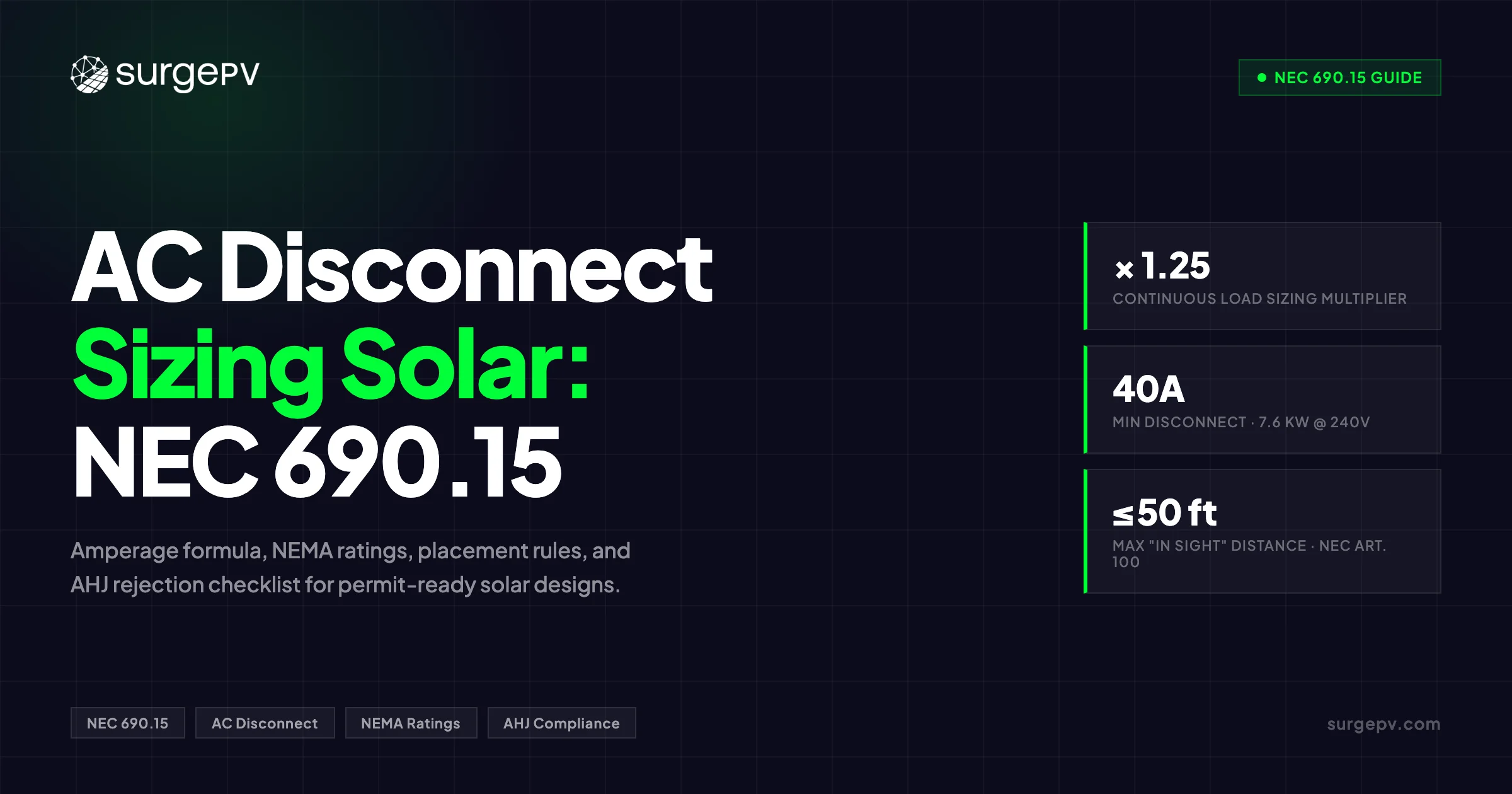
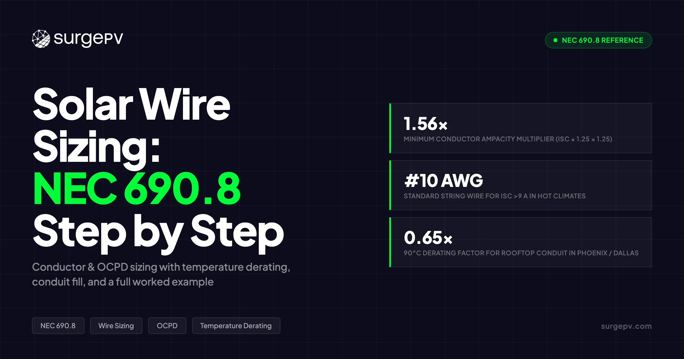
Minimum conductor ampacity = Isc × 1.25 × 1.25 (the “156% rule”). In hot climates with rooftop conduit, temperature derating can reduce #10 AWG THWN-2 from 40 A to 26 A — making that the governing factor, not the base formula. Always run both NEC 690.8(B)(1) and (B)(2) and use the larger result. OCPD size must fall between Isc × 1.56 rounded up and the module’s maximum series fuse rating.
For more on this topic, see Solar Cable Sizing Calculation.
In this guide:
- Why solar wiring uses two separate 1.25 multipliers — and the physics behind each
- How to read NEC Table 310.16 for THWN-2 and USE-2 conductors
- Temperature correction for rooftop conduit — city-by-city reference table
- Conduit fill derating when multiple strings share a raceway
- OCPD sizing under NEC 690.9: floor, ceiling, and DC-listing requirements
- Complete step-by-step worked example for a 3-string, 400W module system
- The most common AHJ rejection triggers — and how to prevent them
Why Solar Wiring Has Its Own Code Section
Standard branch circuit wiring follows NEC Article 310. PV systems have their own rules in Article 690 because a PV source circuit behaves differently from a typical AC load circuit in two ways that affect conductor sizing.
First, a branch circuit serving a lighting load draws current intermittently. A PV string produces current continuously whenever sunlight is available — often for 6 to 10 hours per day. That continuous duty triggers NEC 210.20(A), which limits continuous loads to 80% of a device’s rated ampacity (or equivalently, requires conductors sized at 125% of the load).
Second, solar irradiance can briefly exceed the Standard Test Condition of 1,000 W/m² due to cloud edge reflection, high-elevation sites, or albedo from adjacent surfaces. A module rated at 10 A short-circuit current at STC can briefly produce 11–12 A in the field. NEC 690.8(A)(1) accounts for this with its first 1.25 multiplier.
These two factors stack: NEC 690.8 requires conductors sized for irradiance spikes AND continuous operation — not just one.
The NEC 690.8 Formula — Both Multipliers Explained
Step 1: Maximum Circuit Current — NEC 690.8(A)(1)
The first calculation converts module Isc (from the datasheet at STC) to the maximum circuit current the NEC uses for all downstream sizing:
Maximum Circuit Current = Isc × 1.25
The 1.25 factor is the NEC’s code-standard irradiance margin. Standard Test Conditions assume 1,000 W/m² and 25°C cell temperature. In practice, irradiance can reach 1,100–1,200 W/m² momentarily. The NEC uses 1.25× as a worst-case — it does not require site-specific irradiance studies.
Step 2: Minimum Conductor Ampacity — NEC 690.8(B)(1) — Method A
The second 1.25 converts maximum circuit current into minimum conductor ampacity:
Minimum Ampacity (Method A) = Maximum Circuit Current × 1.25 = Isc × 1.5625
This factor comes from the continuous load rule. NEC 210.20(A) requires conductors for continuous loads (3+ hours at maximum) be sized at 125% of the load. Solar panels run for 6–10 hours daily, so the rule applies in full.
Combined: 1.25 × 1.25 = 1.5625 — typically rounded to 1.56 and called the “156% rule.”
Method A vs Method B
The NEC gives designers two ways to find minimum conductor ampacity:
| Method | Calculation | When It Governs |
|---|---|---|
| (B)(1) — Method A | Isc × 1.25 × 1.25 | Mild climates, low conduit fill |
| (B)(2) — Method B | Max Current ÷ (Temp Factor × Fill Factor) | Hot climates or high conduit fill — often requires larger wire |
The rule: calculate both. The conductor must satisfy the larger of the two results.
Method B is not a shortcut. In Phoenix with 43°C ambient and rooftop conduit, Method B typically governs and requires a larger conductor than Method A alone would show.
Five-Step Calculation Summary
| Step | Operation | Result |
|---|---|---|
| 1 | Module Isc from datasheet | Starting current |
| 2 | × 1.25 | Maximum Circuit Current — NEC 690.8(A) |
| 3 | × 1.25 | Method A Minimum Ampacity |
| 4 | ÷ (Temp Factor × Fill Factor) | Method B Required Base Ampacity |
| 5 | Select larger of Step 3 or Step 4 | Look up in NEC Table 310.16 |
The “156% Rule” in Plain Terms
Multiply any module’s Isc by 1.56. The conductor and OCPD must handle at least that much current continuously. A 10 A Isc module requires conductors rated for at least 15.6 A — before any derating for temperature or conduit fill.
NEC Table 310.16 — Reading Ampacity for Solar Conductors
Wire Types Used in PV Systems
| Wire Type | Temp Rating | Wet/Dry | Common Use |
|---|---|---|---|
| THWN-2 | 90°C | Both | Conduit wiring — string circuits, homeruns |
| USE-2 | 90°C | Both | Direct burial, outdoor exposed runs |
| XHHW-2 | 90°C | Both | Commercial and high-temperature environments |
| PV Wire (UL 4703) | 90°C | Both | Array wiring — between modules and outside conduit |
| THHN | 90°C | Dry only | Interior only — not suitable for outdoor solar use |
USE-2 and PV Wire (UL 4703) are specifically listed for PV systems under Article 690. THWN-2 is acceptable inside conduit. THHN is not acceptable in outdoor or wet locations — a common AHJ rejection.
NEC Table 310.16 — Copper Conductor Ampacity (30°C Ambient)
| AWG | 75°C Column | 90°C Column |
|---|---|---|
| 14 | 20 A | 25 A |
| 12 | 25 A | 30 A |
| 10 | 35 A | 40 A |
| 8 | 50 A | 55 A |
| 6 | 65 A | 75 A |
| 4 | 85 A | 95 A |
| 2 | 115 A | 130 A |
| 1/0 | 150 A | 170 A |
Source: NEC 2023 Table 310.16, copper conductors
The Terminal Temperature Constraint — NEC 110.14(C)
The most overlooked constraint in solar wire sizing: the ampacity of the entire circuit is limited by the lowest temperature-rated termination in that circuit.
Most residential and small commercial inverters have terminals rated at 75°C. THWN-2 wire is rated at 90°C. When 90°C wire terminates at a 75°C terminal, the circuit’s effective ampacity is governed by the 75°C column — not the 90°C column.
For conductor sizing and OCPD verification, use the 75°C ampacity column unless you have confirmed the inverter terminals are rated above 75°C.
One exception: NEC 690.8(B)(2) allows using 90°C correction factors during the temperature derating calculation. But the final conductor size must still satisfy the 75°C termination limit.
Pro Tip
Check the inverter installation manual’s “Electrical Specifications” section for terminal temperature rating before sizing conductors. If it reads “75°C,” use the 75°C ampacity column for your conductor and OCPD verification — even if you specify THWN-2.
Temperature Correction — The Factor Most Installers Miss
NEC Table 310.16 ampacity values assume an ambient of 30°C (86°F). Installations above that temperature require a correction factor that reduces effective ampacity.
Base Ambient Temperature Correction — NEC 310.15(B)(1)
| Ambient Temp (°C) | 75°C Wire Factor | 90°C Wire Factor |
|---|---|---|
| 26–30 | 1.00 | 1.00 |
| 31–35 | 0.94 | 0.96 |
| 36–40 | 0.88 | 0.91 |
| 41–45 | 0.82 | 0.87 |
| 46–50 | 0.75 | 0.82 |
| 51–55 | 0.67 | 0.76 |
| 56–60 | 0.58 | 0.71 |
| 61–65 | 0.47 | 0.65 |
| 66–70 | 0.33 | 0.58 |
| 71–75 | — | 0.50 |
Source: NEC 2023 Table 310.15(B)(1)(1)
Rooftop Conduit Temperature Adder — NEC 310.15(B)(2)
For raceways or cables exposed to direct sunlight on or above a rooftop, the NEC adds a temperature increment to the ambient before applying correction factors:
| Distance from Roof to Bottom of Conduit | Temperature Adder |
|---|---|
| 0” to ½” | +33°C (+60°F) |
| ½” to 3½” | +22°C (+40°F) |
| 3½” to 12” | +17°C (+30°F) |
| 12” to 36” | +14°C (+25°F) |
Source: NEC 2023 Table 310.15(B)(2)
A standard 1¼” EMT conduit on standoffs places the conduit bottom approximately 1”–2” above the roof — the +22°C category for most residential installs.
City Reference Table — Effective Temperature for Rooftop Conduit
This table uses the +22°C adder (conduit ½”–3½” above roof) and shows the 90°C wire correction factor:
| City | Peak Ambient | + Rooftop Adder | Effective Temp | 90°C Factor |
|---|---|---|---|---|
| Phoenix, AZ | 43°C | +22°C | 65°C | 0.65 |
| Las Vegas, NV | 42°C | +22°C | 64°C | 0.65 |
| Dallas, TX | 40°C | +22°C | 62°C | 0.65 |
| Los Angeles, CA | 38°C | +22°C | 60°C | 0.71 |
| Atlanta, GA | 36°C | +22°C | 58°C | 0.71 |
| Denver, CO | 36°C | +22°C | 58°C | 0.71 |
| Chicago, IL | 34°C | +22°C | 56°C | 0.76 |
| New York, NY | 33°C | +22°C | 55°C | 0.76 |
| Miami, FL | 33°C | +22°C | 55°C | 0.76 |
| Seattle, WA | 29°C | +22°C | 51°C | 0.82 |
Mini-example — Phoenix derating:
- #10 AWG THWN-2 base ampacity at 90°C column: 40 A
- Temperature correction at 65°C: 0.65
- Effective ampacity: 40 × 0.65 = 26 A
- With 75°C terminal constraint: 35 A × 0.65 = 22.8 A
A #10 AWG conductor that passes Method A at 40 A can have an effective ampacity as low as 22.8 A in Phoenix. If the OCPD is 20 A, the wire is protected — but with minimal margin. Many designers in hot climates move to #8 AWG for homeruns specifically for this reason.
Most Common AHJ Rejection
Omitting the NEC 310.15(B)(2) rooftop temperature adder is the leading wiring rejection reason for residential PV permit submissions in hot-climate jurisdictions. Show the temperature calculation on your permit drawings.
Conduit Fill Derating — When Multiple Strings Share a Raceway
More than 3 current-carrying conductors in a single conduit require an additional ampacity reduction. Conductors bundled together cannot shed heat as effectively as isolated ones.
NEC 310.15(C)(1) Adjustment Factors
| Current-Carrying Conductors in Conduit | Adjustment Factor |
|---|---|
| 1–3 | 1.00 (no adjustment) |
| 4–6 | 0.80 |
| 7–9 | 0.70 |
| 10–20 | 0.50 |
| 21–30 | 0.45 |
| 31–40 | 0.40 |
Source: NEC 2023 Table 310.15(C)(1)
What Counts as Current-Carrying in a PV Circuit
Count toward fill:
- All ungrounded DC conductors (positive and negative of each string)
Do not count:
- Equipment Grounding Conductors (EGC) — bare copper or green insulation
- Spare conductors not energized
- Balanced neutral conductors in 3-phase AC circuits
A combiner box with 4 parallel strings has 8 current-carrying conductors in the pre-combiner conduit (4 positive + 4 negative). Adjustment factor: 0.80.
If those strings run in separate conduits to the combiner, each conduit holds only 2 current-carrying conductors. Factor: 1.00 — no fill adjustment.
Temperature and fill derating stack:
Combined Derate = Temp Correction Factor × Fill Adjustment Factor
In Dallas with 6 conductors in one conduit: 0.65 × 0.80 = 0.52. A #10 AWG (40 A base at 90°C) dererates to 40 × 0.52 = 20.8 A. A 20 A OCPD is right at the wire’s effective ampacity — any further stress pushes it over.
Step-by-Step Worked Example — 3-String System in Dallas, TX
This example uses a real Tier-1 400W module to demonstrate the complete NEC 690.8 calculation for string conductors and the homerun conductor.
Module and System Specifications
Module: Trina Solar TSM-400DE15H(II) — representative Tier-1 400W module
| Parameter | Value |
|---|---|
| Peak Power (Pmax) | 400 Wp |
| Voltage at Pmax (Vmp) | 41.1 V |
| Open-Circuit Voltage (Voc) | 50.4 V |
| Short-Circuit Current (Isc) | 10.18 A |
| Current at Pmax (Imp) | 9.74 A |
| Maximum Series Fuse Rating | 20 A |
System configuration:
| Parameter | Value |
|---|---|
| Modules per string | 10 |
| Parallel strings | 3 |
| String DC voltage | 41.1 V × 10 = 411 V |
| Inverter terminal rating | 75°C |
| Conduit location | Rooftop, ~2” above roof surface |
| Ambient design temperature | 40°C (Dallas, TX) |
| String conduit fill | 2 current-carrying conductors per string run |
| Homerun conduit fill | 2 current-carrying conductors |
| Homerun length (one-way) | 80 ft |
| Voltage drop target | ≤ 2% |
Part 1: String Conductor Sizing
Step 1 — Maximum Circuit Current (NEC 690.8(A))
10.18 A × 1.25 = 12.73 A
Step 2 — Method A Minimum Ampacity (NEC 690.8(B)(1))
12.73 A × 1.25 = 15.91 A
Look up 15.91 A in Table 310.16 at 75°C column (inverter terminal constraint):
- #12 AWG: 25 A ✓
Method A says #12 AWG passes.
Step 3 — Method B with Corrections (NEC 690.8(B)(2))
Effective temperature:
- Dallas peak ambient: 40°C
- Rooftop conduit adder (2” above roof): +22°C
- Effective ambient: 62°C
From NEC 310.15(B)(1) at 62°C for 90°C wire: correction factor = 0.65 (between the 61–65°C row at 0.65 and 66–70°C row at 0.58)
String conduit carries 2 current-carrying conductors: fill factor = 1.00
Required base ampacity:
12.73 A ÷ (0.65 × 1.00) = 19.58 A
Look up 19.58 A at 90°C column:
- #12 AWG: 30 A ✓
Verify against 75°C terminal constraint with derating applied:
- #12 AWG at 75°C: 25 A
- Derated: 25 × 0.65 = 16.25 A
- Required: 12.73 A ✓ — passes with 3.52 A margin (28%)
Step 4 — Compare Methods
| Method | Required | Wire |
|---|---|---|
| Method A | 15.91 A | #12 AWG (25 A at 75°C) |
| Method B | 19.58 A | #12 AWG (30 A at 90°C, 16.25 A derated) |
Both methods clear #12 AWG. The effective derated ampacity of #12 AWG at 75°C in Dallas is 16.25 A — 28% above the 12.73 A requirement with this module.
#10 AWG derated at 75°C: 35 × 0.65 = 22.75 A — 79% above the requirement, giving comfortable inspection margin.
Design decision: #12 AWG is technically compliant for this module in Dallas, but #10 AWG is the standard practice in hot climates — particularly because many residential modules have Isc above 11 A, where the margin disappears.
Step 5 — OCPD Sizing (NEC 690.9)
String-level fuses are required: 3 parallel strings create a backfeed path.
Minimum OCPD = 10.18 A × 1.56 = 15.88 A
Next standard size per NEC 240.6(A): 20 A
- 20 A ≤ module maximum series fuse rating (20 A) ✓ — at the ceiling, acceptable
- 20 A ≤ #12 AWG ampacity at 75°C (25 A) ✓
Step 6 — Voltage Drop Check (String)
String voltage: 411 V. Operating current: 12.73 A. #12 AWG resistance: 1.98 Ω/1,000 ft at 75°C (NEC Chapter 9, Table 8). One-way run: 80 ft.
VD% = (2 × 80 × 12.73 × 1.98) / (411 × 1,000) × 100 = 0.99% ✓
Part 2: Homerun Conductor Sizing
The homerun carries the combined output of all 3 strings from the combiner box to the inverter.
Step 1 — Total Short-Circuit Current
3 × 10.18 A = 30.54 A
Step 2 — Maximum Circuit Current (NEC 690.8(A))
30.54 A × 1.25 = 38.18 A
Step 3 — Method A Minimum Ampacity
38.18 A × 1.25 = 47.72 A
At 75°C column: #6 AWG = 65 A ✓
Method A says #6 AWG is sufficient.
Step 4 — Method B with Corrections
The combiner merges all strings internally. The homerun conduit carries 2 current-carrying conductors (one positive bus, one negative bus). Fill factor: 1.00.
Temperature: same as above — 62°C effective, factor = 0.65.
Required base ampacity = 38.18 ÷ (0.65 × 1.00) = 58.74 A
At 90°C column: #6 AWG = 75 A ✓
Verify against 75°C terminal constraint with derating:
- #6 AWG at 75°C: 65 A
- Derated: 65 × 0.65 = 42.25 A
- Required: 38.18 A ✓ — passes with 10.6% margin
Governing homerun conductor: #6 AWG
Step 5 — Voltage Drop Check (Homerun)
#6 AWG copper resistance: 0.491 Ω/1,000 ft at 75°C (NEC Chapter 9, Table 8). Operating current: 38.18 A. One-way: 80 ft.
VD% = (2 × 80 × 38.18 × 0.491) / (411 × 1,000) × 100 = 0.73% ✓
Summary — Dallas 3-String System
| Circuit | Wire Size | 75°C Ampacity | Derated Effective | OCPD |
|---|---|---|---|---|
| String conductors (×3 circuits) | #12 AWG THWN-2 | 25 A | 16.25 A | 20 A gPV fuse |
| Homerun conductor | #6 AWG THWN-2 | 65 A | 42.25 A | Inverter input OCPD |
Skip the Spreadsheet — SurgePV Sizes Every Conductor Automatically
Input your module specs and SurgePV calculates string wire, homerun wire, and OCPD sizes per NEC 690.8 — including temperature derating for your city and conduit fill adjustment.
Book a DemoNo commitment required · 20 minutes · Live project walkthrough
For a direct comparison, see Arka 360 vs SurgePV.
OCPD Sizing Under NEC 690.9 — Floor, Ceiling, and DC Requirements
Overcurrent protection in a PV DC circuit differs from a standard branch circuit breaker in three ways: there is a minimum size floor, a maximum size ceiling, and a DC listing requirement.
When OCPD Is Not Required
NEC 690.9(A) exempts PV circuits from OCPD when:
- Conductors have ampacity equal to or exceeding the maximum circuit current, AND
- Current from all sources cannot exceed the device rating on the module or power converter
A single-string system with no backfeed path — where the inverter is the only path for current — typically does not need string-level fusing. The inverter’s own input protection covers it.
For 3 or more parallel strings, string-level fusing is required. A fault in one string creates a current path from healthy strings back through the faulted conductor. That combined current can exceed the conductor’s rated ampacity.
OCPD Floor — Minimum Size
Minimum OCPD = Isc × 1.56, rounded UP to the next standard size
Standard sizes from NEC 240.6(A): 15, 20, 25, 30, 35, 40, 45, 50, 60, 70, 80, 90, 100…
For Isc = 10.18 A: 10.18 × 1.56 = 15.88 A → next standard size = 20 A
OCPD Ceiling — Maximum Size
Maximum OCPD ≤ Module Maximum Series Fuse Rating (from nameplate)
This rating is the highest OCPD the module can safely withstand during a reverse-current fault without damage. It is on the module nameplate and in the datasheet.
If the calculated floor exceeds the ceiling: the module cannot be used in that parallel string count. Options are to reduce the number of parallel strings, select a module with a higher fuse rating, or redesign the array.
DC-Rated Equipment Only
AC circuit breakers will not safely interrupt DC current. A DC arc does not self-extinguish at a current zero crossing the way an AC arc does.
All OCPDs in PV DC circuits must be:
- Listed for DC service — UL 248-14 gPV cartridge fuses, or DC-rated circuit breakers
- Voltage-rated at or above the maximum system DC voltage (calculated per NEC 690.7) Read DC Bus Voltage Optimization for a complete walkthrough.
NEC 2026 — 690.9(D) PV Marking
Starting with the NEC 2026 cycle, OCPDs in PV DC circuits must be marked “Photovoltaic” or “PV.” This prevents AC-rated devices from being substituted during installation or future service. Plan for this marking requirement on projects designed to meet 2026 code.
AWG 10 vs AWG 12 — String Wire Selection Guide
The most common field question: does a residential string need #10 or #12 AWG? The answer depends on module Isc, local climate, and conduit installation method.
Decision Matrix
| Parameter | #12 AWG THWN-2 | #10 AWG THWN-2 |
|---|---|---|
| 75°C base ampacity | 25 A | 35 A |
| 90°C base ampacity | 30 A | 40 A |
| NEC 240.4(D) max OCPD | 20 A | 30 A |
| Best for | Isc ≤ 9 A, mild climates | Isc 10–13 A, any climate |
| Cost per 100 ft (copper) | Lower | Higher (varies by supplier) |
When #12 AWG Is Sufficient
- Module Isc ≤ 8.5 A — minimum OCPD is 13.3 A, well within #12 AWG’s 25 A capacity
- Installation in a climate below 35°C peak ambient
- Conduit not exposed to direct sunlight (underground or interior)
When #10 AWG Is Required
- Module Isc ≥ 10 A with rooftop conduit in any US climate warmer than the Pacific Northwest
- Derated ampacity of #12 AWG falls below the OCPD rating
- Hot-climate installs where the #12 AWG margin drops below 10% above the OCPD rating
Scenario Table by Climate and Module Isc
| Module Isc | Min OCPD | 30°C ambient | Dallas (62°C effective) |
|---|---|---|---|
| 8.5 A | 15 A | #12 AWG ✓ (25 A > 15 A) | #12 AWG ✓ (16.25 A vs 13.3 A req, 22% margin) |
| 10.0 A | 20 A | #12 AWG ✓ (25 A > 20 A) | #12 AWG — marginal (16.25 A vs 15.6 A req, 4% margin) |
| 11.0 A | 20 A | #12 AWG ✓ | #10 AWG recommended |
| 10.18 A | 20 A | #12 AWG ✓ | #12 AWG ✓ (16.25 A vs 12.73 A req, 28% margin) |
| 13.0 A | 25 A | #10 AWG ✓ (35 A > 25 A) | #10 AWG ✓ (22.75 A > 20.3 A req) |
| 14.5 A | 25 A | #10 AWG ✓ | #8 AWG in Phoenix/Dallas |
In hot climates with rooftop conduit, #10 AWG is the practical standard for any module with Isc above 9 A. Using solar design software that applies automatic temperature derating catches marginal cases before they reach inspection.
Common Mistakes and AHJ Rejection Triggers
These are the most frequent wiring errors found during permit review and field inspection.
| Mistake | Why It Happens | Consequence |
|---|---|---|
| Ignoring rooftop temperature adder (NEC 310.15(B)(2)) | Designer sizes at 30°C table values, skips adder | Ampacity drops 25–42%; OCPD may exceed conductor rating |
| Applying only one 1.25 factor | Motor-circuit convention (NEC 430) applied to solar | Conductors undersized by 25% |
| Using 90°C ampacity when terminals are 75°C | NEC 110.14(C) terminal rule overlooked | Termination overheating; inverter warranty void |
| Oversizing OCPD “to be safe” | Installer selects next-next standard size up | OCPD won’t protect conductor before insulation melts |
| Missing conduit fill derating | 6+ current-carrying conductors in conduit, no adjustment | 20–50% ampacity reduction unaccounted for |
| Using AC-rated breakers in DC circuits | Cost substitution or unfamiliarity with DC arc | DC arc not interrupted; catastrophic failure |
| Sizing for ampacity only, skipping voltage drop | Ampacity tables are code minimums; VD is a performance check | VD over 3% causes MPPT inefficiency and production loss |
| Applying 156% per string then summing | Misunderstanding of parallel current math | Overstates OCPD requirement by ~25% |
| OCPD exceeds module max series fuse rating | Calculated floor exceeds the ceiling | Module not protected from reverse current; warranty void |
Good solar software flags every one of these conditions during the design process. Each of these mistakes is a recalculation — or a permit rejection — that gets caught before drawings are submitted.
The Calculation Sequence — Start to Finish
When sizing a system’s conductors, the sequence is:
- Pull module Isc from the datasheet (STC value, not NOCT)
- Identify installation climate and conduit height above roof
- Calculate maximum circuit current: Isc × 1.25
- Run Method A: × 1.25, look up in Table 310.16 at 75°C column
- Run Method B: apply temperature factor × fill factor, divide max current, look up at 90°C column
- Verify Method B result against 75°C terminal constraint
- Select the larger result from Method A and Method B
- Size OCPD: Isc × 1.56, round up, verify against module max fuse rating
- Check voltage drop for each run — target ≤ 2%
- Repeat for homerun with combined string current
A residential 3-string system has at minimum 2 distinct conductor calculations. A commercial system with multiple combiner boxes can have 8–12 separate calculations. Solar proposal software that automates NEC 690.8 sizing produces a permit-ready single-line diagram with wire sizes called out, saving 1–3 hours per design on systems above 30 kW.
Frequently Asked Questions
What size wire do I need for solar panels?
The minimum wire size depends on module Isc, local climate, and conduit installation method. Under NEC 690.8, conductors must carry at least Isc × 1.56 before any derating. For a 400W module with Isc = 10.18 A, that’s 15.9 A minimum — but rooftop conduit in Dallas or Phoenix can require larger wire once temperature derating is applied. Always run the temperature-corrected Method B calculation before finalizing wire size.
What is the 1.56 rule in NEC 690.8?
The 1.56 rule comes from two 1.25 multipliers applied in sequence. The first (NEC 690.8(A)(1)) converts module Isc to maximum circuit current, accounting for irradiance that can exceed STC conditions. The second (NEC 690.8(B)(1)) accounts for continuous operation under the NEC continuous load rule. Combined: 1.25 × 1.25 = 1.5625, rounded to 1.56.
Can I use AWG 12 wire for residential solar panels?
In mild climates with conduit not exposed to direct sunlight, yes — for modules with Isc at or below 10 A. In hot climates with rooftop conduit, the derating often makes #12 AWG marginal. For Isc above 10 A, or any rooftop conduit installation in a climate warmer than 35°C peak ambient, #10 AWG is the standard practice choice.
What is the difference between NEC 690.8(B)(1) and (B)(2)?
Method (B)(1) multiplies maximum circuit current by 1.25. Simple and conservative. Method (B)(2) divides maximum circuit current by the product of temperature correction factor and conduit fill factor, then looks up the required conductor size. You must calculate both and use the larger result. Method B is not a shortcut: in hot climates, it typically requires a larger conductor than Method A.
Do I need a fuse for every solar string?
Not always. For a single-string system without backfeed risk, NEC 690.9(A) permits omitting string-level fusing. For 3 or more parallel strings, string-level OCPDs are required — a fault in one string creates a reverse current path from the healthy strings that can exceed the conductor’s ampacity. The fuse rating must fall between Isc × 1.56 rounded up and the module’s maximum series fuse rating.
Can I use THHN wire for solar panel wiring?
No. THHN is rated for dry locations only. Use THWN-2 inside conduit, USE-2 for outdoor or direct-burial runs, or UL 4703 PV Wire for array wiring outside conduit. THHN on permit drawings is a common AHJ rejection — it should be replaced with THWN-2 before submitting.