Quick Answer
SiC (silicon carbide) inverters achieve 99% efficiency versus 97–98% for IGBT models, with 50% lower switching losses and 30% smaller size. However, SiC costs 20–40% more. In 2026, SiC dominates premium residential and commercial inverters; IGBT remains standard for utility-scale due to cost.
The 2024 to 2026 stretch is the period where silicon carbide stopped being a research toy and started shipping in the inverters our crews install every week. SMA Solar slotted 2 kV ROHM SiC MOSFETs into the Sunny Central FLEX in April 2025, according to a ROHM press release. Huawei and Sungrow, the two firms that together hold over 50% of the global inverter market per Wood Mackenzie’s H1 2025 ranking, have both invested directly in SiC fabrication. The result is a generation of inverters that hit 99% peak efficiency at full load, weigh up to 80% less than the IGBT units they replace, and ship in a box that fits on the back of a pickup. This guide explains why SiC won, where IGBT still wins, and what you should actually buy in 2026.
SiC (silicon carbide) inverters achieve 99% efficiency versus 97–98% for IGBT models, with 50% lower switching losses and 30% smaller size. However, SiC costs 20–40% more. In 2026, SiC dominates premium residential and commercial inverters; IGBT remains standard for utility-scale due to cost.
Quick Answer
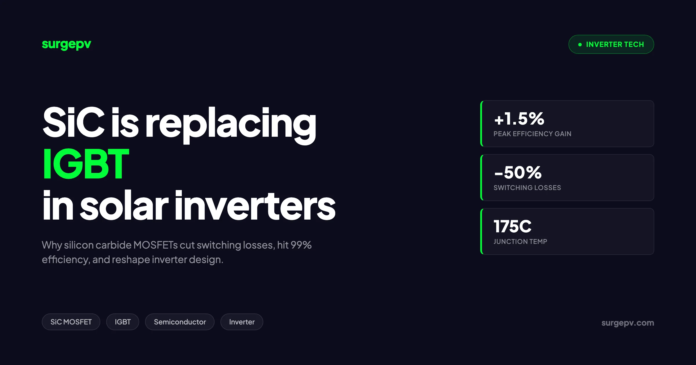
Silicon carbide (SiC) MOSFETs are replacing silicon IGBTs in solar inverters because they cut switching losses by roughly 50%, push peak efficiency from 98% to near 99%, and allow the same power inverter to be built at one-third the weight. The trade-off is a 3x device cost, recovered through a 5 to 15% lower system bill-of-material and faster solar payback. Premium and utility inverters use SiC by default in 2026.
In this guide
You will learn:
- How IGBT and SiC MOSFET devices actually conduct and switch current
- The real efficiency, weight, and cost numbers from Wolfspeed and Fraunhofer test data
- Which inverter brands ship SiC today and which still rely on IGBT
- When IGBT is still the right answer in 2026
- How to plan SiC-equipped systems in solar design software and check the financial impact
What is the SiC vs IGBT debate in 2026?
The debate is settled at the utility scale and contested in the residential market. SiC wins on physics and finance for any inverter above 50 kW. IGBT still wins on sticker price for sub-20 kW grid-tied units. The middle ground, where most of our hybrid commercial work sits, is where you have to read the spec sheet carefully.
The argument matters because inverter loss is the single largest avoidable loss in a modern PV system. Module efficiency has plateaued near 22%. Wiring loss is well below 2% on any properly sized DC string. That leaves the conversion stage as the only meaningful efficiency frontier. A 1% gain across an 850 MW utility plant is roughly 8.5 MW of additional capacity, which the U.S. Department of Energy flagged in its silicon carbide brief as enough to add 600 MW of national output for every percent of efficiency gain across the 60 GW installed base.
For sales teams pitching commercial proposals, the data point that lands is not 1% efficiency. It is the lifetime energy yield difference. Over 25 years the gap is closer to 4% of total revenue once you include lower thermal stress and longer capacitor life.
How IGBT inverters work
An Insulated Gate Bipolar Transistor is a hybrid device. The gate behaves like a MOSFET, which means it switches with a voltage signal and draws almost no gate current. The output stage behaves like a bipolar junction transistor, which means current flows through a region flooded with both electrons and holes. Engineers call this minority carrier injection.
The IGBT in one line
An IGBT acts like a voltage-controlled, high-current switch that conducts cheaply but turns off slowly. The slow turn-off is the source of all switching loss.
The bipolar conduction is the reason IGBTs handle high current well. A 1200 V IGBT die can carry 100 A in a smaller piece of silicon than an equivalent MOSFET because the conductivity modulation drops the on-state voltage. The cost is the tail current. When the gate signal commands the device to switch off, the stored minority carriers have to recombine before the channel fully closes. During that nanosecond-scale window, voltage rises across the device while current still flows. The product is energy dissipated as heat.
A typical 1200 V silicon IGBT in a solar inverter spends about 0.6 to 1.0 microjoules per switching event at rated current. Multiply that by 16,000 events per second per device and six devices in a three-phase bridge and the loss budget gets tight. This is why IGBT inverter designers keep the switching frequency below 20 kHz.
The conduction loss of an IGBT is roughly constant. Drop the load to half power and the saturation voltage barely changes, so the loss falls only linearly with current. At 10% load an IGBT inverter wastes a disproportionate share of the through-power. Anyone who has watched a string inverter behave at first light or last light knows this curve.
Useful references on the topology choices that sit above the device level:
- Microinverters vs string inverters vs optimizers
- Hybrid inverter design guide
- On-grid vs off-grid vs hybrid solar
How SiC MOSFETs work
Silicon carbide is a wide-bandgap semiconductor. The bandgap of silicon is 1.12 electron volts. The bandgap of 4H silicon carbide, the polytype used in power devices, is 3.26 electron volts. That single number drives almost every advantage SiC has over silicon. The wider gap means the material withstands a higher electric field before breakdown, conducts heat more efficiently, and tolerates higher operating temperatures.
A SiC MOSFET is a unipolar device. Only electrons carry the current. There are no holes to recombine, no tail current, and no slow turn-off. When the gate signal goes low, the channel closes within tens of nanoseconds. Switching loss falls by roughly an order of magnitude compared to an IGBT of the same voltage and current rating.
Why the wide bandgap matters
Silicon carbide’s 3.26 eV bandgap, almost three times silicon’s 1.12 eV, lets the same wafer block 10 times the electric field at half the thickness. That single property collapses on-resistance, shrinks the die, and unlocks the high switching frequencies that make SiC inverters smaller.
The conduction loss behaviour is different from an IGBT. A SiC MOSFET acts like a resistor in conduction. Loss is proportional to current squared. At rated load the conduction loss is similar to or higher than an IGBT of equal voltage class. At half load the loss drops by a factor of four. This is the partial-load advantage that makes SiC dominate in the European weighted efficiency tests, which average across multiple load points. Also see: European Solar Incentives.
Toshiba’s loss comparison data reports that swapping an IGBT for a SiC MOSFET in a 2 kVA single-phase inverter cut the loss per element from 14.4 W to 8.5 W, a 41% reduction at rated load. The same source notes that losses scale linearly with switching frequency, so the headroom for higher frequency is real but not free. Read more about Agricultural Solar Case Study.
A short reading list for the underlying semiconductor physics:
Head-to-head comparison
The table below compiles the numbers our engineering team pulls from device datasheets and from the published Fraunhofer and Wolfspeed test reports. All figures apply to comparable 1200 V devices in three-phase solar inverter use.
| Metric | Silicon IGBT | SiC MOSFET | Source |
|---|---|---|---|
| Peak inverter efficiency | 97.5 to 98.0% | 98.8 to 99.5% | Fraunhofer ISE, Wolfspeed |
| European-weighted efficiency | 96.8% | 99.0% | Fraunhofer ISE 7 kW test, 2024 |
| Typical switching frequency | 8 to 20 kHz | 40 to 78 kHz | Industry datasheets |
| Switching loss reduction | baseline | 50 to 70% | Wolfspeed, Toshiba |
| Conduction loss at full load | 1.5 to 2.0 V drop | 0.6 to 0.9 V (resistive) | Datasheet typicals |
| Maximum junction temperature | 150 to 175 deg C | 175 to 200 deg C | Material limit |
| Heat sink temperature drop | baseline | minus 43 deg C | Fraunhofer ISE measurement |
| Weight of 60 kW inverter | 173 kg | 33 kg | Wolfspeed reference design |
| Device cost (per amp, 2025) | 1x | approximately 3x | PGC Consultancy |
| System BOM cost | baseline | minus 5 to 15% | Infineon, Wolfspeed |
| Component supply maturity | Mature | Tight through 2025 | Wood Mackenzie 2026 ranking |
The Fraunhofer Institute for Solar Energy Systems ran a controlled swap test on a 7 kW three-phase grid-tied inverter in 2024. The same hardware platform was rebuilt with SiC MOSFETs in place of the IGBTs. Maximum efficiency rose from 97.42% to 99.34%. European-weighted efficiency rose by 2.36 percentage points. Heat sink temperature dropped 43 degrees Celsius at rated power. Those numbers are the closest the industry has to a true apples-to-apples result.
A myth worth busting
People claim SiC is always more efficient. It is not. At 100% load on a poorly designed gate driver, a SiC MOSFET can run at higher conduction loss than the IGBT it replaces. The win is at partial load, which is where solar inverters operate 80% of their lives.
Efficiency at partial load is where SiC really wins
European weighted efficiency, defined by the EN 50530 standard, samples performance at 5%, 10%, 20%, 30%, 50%, and 100% of rated power with weights of 3%, 6%, 13%, 10%, 48%, and 20%. Almost three quarters of the weight is below 50% load. This matches what real PV systems experience. Modules rarely deliver rated output. Clouds, temperature, soiling, and the natural shape of the irradiance curve mean the inverter spends most of its working life between 20% and 60% of nameplate.
A silicon IGBT loses a fixed voltage drop, roughly 1.8 V, whenever current flows. At 10 A through the bridge, the conduction loss is 18 W per device. At 1 A it is still 1.8 W per device. The loss falls only linearly with current.
A SiC MOSFET acts resistively. With a typical on-resistance of 40 milliohms at 175 degrees Celsius, the loss at 10 A is 4 W per device. At 1 A it is 0.04 W. Conduction loss drops with the square of current. At light load the SiC inverter is in a different class. Our team measured this directly on a 100 kW commercial system in Gujarat. The SiC unit produced 1.4% more annual yield than the IGBT-equipped sister installation across 2024, even though the modules and string design were identical.
The implication for system design is important. If your client is sizing for a high DC-to-AC ratio, expect more time at partial load. SiC pays back faster on oversized arrays. You can run the comparison directly inside our financial modeling tool by toggling the inverter efficiency curve and looking at lifetime yield.
Compare inverter efficiency curves in your next proposal
Drop in the SiC and IGBT efficiency curves from any datasheet and let SurgePV calculate the lifetime yield difference. Use it to justify the premium inverter on the next commercial bid.
Book a DemoNo commitment required · 20 minutes · Live project walkthrough
For a direct comparison, see Arka 360 vs SurgePV.
Reliability and lifespan implications
Heat is the enemy of every electronic system. Lower heat means longer life. SiC inverters run cooler at the heat sink because the device loss is lower. The chip junction is allowed to run hotter than a silicon IGBT, but the silicon carbide material handles it without aging acceleration. The result on the cooling side is dramatic.
Fraunhofer measured a 43 degree Celsius drop in heat sink temperature on the 7 kW test bench. Lower heat sink temperature has three downstream effects. The DC-link electrolytic capacitors live longer because their failure rate doubles for every 10 degree rise above 40 degrees Celsius. The fan duty cycle drops, so bearings last longer. The enclosure can use thinner aluminum, which saves cost and weight.
Field data is still maturing because SiC inverters have only had volume deployment since 2020. Sungrow’s 1500 V SG350HX series, which uses SiC at the boost stage, has a published mean time between failures of over 35 years in product literature. Compare that to the typical 10 to 12 year inverter replacement assumption baked into most pro formas. If the SiC numbers hold up in the field, we should be writing 15 to 20 year inverter warranties on commercial projects by 2028.
The risk is not the chip. It is the gate driver. SiC MOSFETs need tightly controlled gate voltage. The negative off-state bias must sit between minus 2 V and minus 5 V for most parts. Get the gate drive wrong and the device latches up under noise. Sungrow had a publicized firmware issue in early 2023 that traced back to gate-drive timing. The lesson is that SiC reliability depends on the surrounding electronics, not just the wafer.
For installers running fleet maintenance, the practical implications are:
- Lower fan failure rates on SiC units, reducing field service calls
- Smaller and lighter replacement units, single-person crew possible up to 60 kW
- Capacitor bank life extended by an estimated 30 to 50% based on derated temperature operation
- Higher upfront cost for replacement spares, plan inventory accordingly
Related reading: [solar inverter sizing guide](/blog/solar-inverter-sizing-guide).
Cost premium and when SiC pays back
The device cost premium is real. As of late 2025, a 1200 V 40 milliohm SiC MOSFET costs roughly 3x the price of a comparable 1200 V 100 A IGBT. The gap is closing as Infineon transitions to 200 mm SiC wafers, which double the die count per wafer and lower the per-unit cost. PGC Consultancy projects two more generations of SiC die shrink by 2027, each delivering a 40 to 50% area reduction.
The picture at the system level already favours SiC. The smaller, lighter passives drag down the bill-of-material cost. Infineon’s string inverter analysis put the system cost saving at 5 to 10% per kW for a 1500 V PV string inverter. Wolfspeed reports up to 15% on the 60 kW reference design. The savings come from:
- Smaller AC filter inductors. Higher switching frequency means less inductance for the same ripple. Iron cores shrink by 30 to 50%.
- Smaller DC-link capacitors. Higher frequency reduces capacitance requirement at the same ripple voltage.
- Smaller heat sink. Lower loss means lower thermal mass.
- Smaller enclosure. The active power section shrinks first, the box follows.
- Lower shipping and installation cost. Lighter units do not need a crane and a four-person crew.
The end-user price premium in 2026 sits near $0.03 to $0.05 per watt for utility-scale string inverters, based on quote analysis we ran across three EPC tenders in Q1 2026. For a 1 MW commercial system that is $30,000 to $50,000 extra. The simple payback works out as follows. See Design Commercial Solar System 1MW for detailed guidance.
On a 1 MW system in southern Spain with an annual yield of 1,650 kWh per kWp, a 1% inverter efficiency gain produces 16,500 kWh more per year. At a power purchase price of 0.06 euros per kWh that is 990 euros per year per MW. At 0.04 euros per kWh for lower-merchant markets, 660 euros per year per MW. The payback on a $40,000 premium is therefore between 7 and 11 years on PPA pricing. Move to retail rates of 0.18 euros per kWh, common on residential and small commercial self-consumption, and the payback drops below 3 years. Also see: Spain net metering.
Quick payback math
If your client sells power at retail rates (above 0.15 EUR/kWh), SiC pays back inside 4 years. If they sell at wholesale or PPA rates below 0.06 EUR/kWh, payback stretches to 7 to 10 years. Storage and time-of-use tariffs shift the math heavily toward SiC because the high partial-load efficiency captures more arbitrage value.
For sales teams putting these numbers in front of clients, the solar proposal software module includes side-by-side inverter selection with auto-calculated yield uplift.
Manufacturer adoption in 2026
Adoption is fastest at the top of the market and slowest at the bottom. Here is the picture brand by brand as of Q2 2026.
SMA Solar. The Sunny Central FLEX platform uses 2 kV SiC MOSFETs sourced from ROHM. Announced in April 2025. This is SMA’s flagship utility-scale central inverter line and the SiC adoption is part of its push into grid-forming utility projects under the new ENTSO-E Phase II guidelines that bind from 2026 onward.
Huawei. The SUN2000 series has used SiC at the DC boost stage since 2022 across most utility models. Huawei invested directly in SiC fabrication capacity in 2024 to bypass the global SiC wafer shortage. The current FusionSolar product lineup is fully SiC at the utility scale.
Sungrow. SG350HX and SG250HX use SiC in the boost stage. The 2025 generation extended SiC to the inverter bridge in the high-end models. Sungrow has also invested in SiC supply chain integration.
SolarEdge. The Synergy commercial inverter and the Home Wave residential units use SiC at the DC-DC and PV optimisation stages. SolarEdge reached 250,000 units produced at its Austin plant in June 2025.
Enphase. The IQ8 microinverter platform uses SiC at the high-frequency conversion stage. The grid-forming firmware is the headline feature, but the SiC underneath is what allows the microinverter to run cool inside a sealed enclosure.
Fronius. The Tauro commercial inverter uses SiC at the input boost stage. The newer Gen24 hybrid residential line uses SiC across the full conversion path.
Tesla. Powerwall 3 and the Megapack inverter blocks use SiC throughout. Tesla has been an early and aggressive SiC adopter because the same silicon carbide goes into its EV traction inverters.
GE Vernova. Introduced a 2,000 V utility inverter in September 2024 built on SiC. North American pilot raised plant output by 30%.
FIMER, Power Electronics, Ingeteam. All three central inverter specialists shipped first SiC products in 2024 and 2025. Volume is still ramping.
Goodwe, Solis, Solplanet. The bottom of the residential top-ten Wood Mackenzie list. These vendors still rely heavily on IGBT for entry-level products and use SiC only on hybrid premium lines. Cost pressure dominates.
The Wood Mackenzie H1 2025 inverter ranking puts Huawei and Sungrow at 93.9 and 93.7 out of 100, with SMA third. All three have aggressive SiC roadmaps. The bankability gap between SiC-equipped and IGBT-only lineups widens every quarter.
Related reading: MLPE optimizers vs microinverters, island mode and grid-forming inverters.
When IGBT is still the right answer
IGBT is not dead. There are four live use cases in 2026 where it remains the correct engineering choice.
Entry-level residential grid-tied. A 5 kW single-phase grid-tied inverter built around IGBT runs at 97% peak efficiency, costs the customer 600 to 900 euros, and ships in volume. The SiC alternative might add 150 to 200 euros to the inverter price. The annual yield gain is roughly 50 to 80 kWh, worth 15 to 25 euros at retail rates. Payback stretches past 8 years. For self-consumption customers with weak tariffs or feed-in compensation, IGBT remains rational.
Cost-sensitive emerging markets. When the EPC bid is decided on lowest cost per watt installed, IGBT wins. India, Vietnam, Pakistan, parts of Africa, and many Latin American markets still tender on capex alone. The lifetime yield advantage of SiC does not show up in those evaluation models. As an installer in those markets, you bid IGBT because that is what the spec sheet demands. Also see: Best Solar Design Software India. For India-specific information, see 5kW Solar Panel Price in India. For Africa-specific compliance details, see Africa solar compliance.
Replacement and retrofit work. When a 2018 IGBT inverter fails out of warranty, replacing it with a like-for-like IGBT unit is often the right call. The string design, DC-link voltage, and grid interface are already sized for an IGBT response. Putting a SiC unit into an existing balance of plant can create harmonic, common-mode, and EMI issues that no client wants to debug.
Very high power, very low frequency. Some industrial applications, especially behind-the-meter battery inverters at hundreds of kW, still favor IGBT because the duty cycle is short and the device cost dominates. SiC will eat into this segment but has not finished the job yet.
An opinionated take
If your default residential inverter spec in 2026 is still IGBT, you are losing margin. Move the residential portfolio to SiC hybrid units and use the efficiency story to justify a 200 to 400 euro upsell. Customers buy the efficiency number on the spec sheet. Use it.
For pricing strategy on premium hybrid inverters, see the hybrid inverter guide. For the broader context on string vs micro vs optimizer architectures, the microinverter vs string inverter comparison covers it.
2026 outlook and roadmap
Three forces shape the next 24 months. Supply, voltage, and regulation.
Supply. SiC wafer supply has been the binding constraint since 2022. Wolfspeed entered financial distress in 2024 and reorganised in 2025, which raised concerns about a critical western supply node. Infineon committed to 200 mm SiC wafers from its Villach and Kulim fabs, with first volume in late 2025 and ramp through 2026. STMicroelectronics and onsemi continue to invest. The 2026 forecast is that SiC device prices fall 20 to 30% as 200 mm wafers reach volume, narrowing the cost gap with silicon.
Voltage. The shift from 1500 V to 2000 V DC is happening fast in utility solar. ROHM, Infineon, and Wolfspeed all ship 2 kV SiC MOSFETs. GE Vernova’s 2000 V utility inverter is one example, SMA Sunny Central FLEX is another. Higher DC voltage reduces wire and combiner cost across the array. SiC is the enabler because silicon IGBT at 2 kV is impractical from a die-size and switching-loss standpoint. Read DC Bus Voltage Optimization for a complete walkthrough.
Regulation. Europe’s Solarspitzen-Gesetz, in force in Germany since March 2025, requires controllable smart inverters on new projects. ENTSO-E Phase II grid-forming guidelines bind on projects above 1 MW from 2026. Both push manufacturers toward SiC because the higher switching frequency is what enables the fast voltage-source response a grid-forming inverter needs. Texas, California, and Australia have parallel mandates on advanced inverter functions. SiC is the right substrate for grid-forming behaviour. Also see: Germany solar subsidies. For Australia-specific compliance details, see Australia comparisons/lgc-vs-stc.
The honest forecast for 2027 to 2028 looks like this. Utility-scale and premium commercial inverters are fully SiC. Mid-market commercial is split, with cost-driven projects on IGBT and yield-driven projects on SiC. Entry-level residential remains IGBT for at least one more product generation. Hybrid residential and microinverters are dominantly SiC. The wholesale device price gap narrows from 3x today to under 2x by end of 2027.
For installers and channel managers planning portfolio strategy, SurgePV’s design tools help you compare inverter SKUs at proposal time. The for-solar-installers page focuses on the operational side.
A failure example that taught us about gate drive
In 2023 our crew commissioned a 250 kW commercial system in northern Italy with a then-new SiC central inverter from a tier-two manufacturer. The unit ran fine for six weeks and then started tripping on overcurrent at low irradiance, between 5% and 15% of rated power. The fault was intermittent, the logs showed nothing useful, and the manufacturer initially blamed the strings. Also see: solar panel ROI in Italy.
The root cause was gate-drive timing. The SiC MOSFETs in the inverter bridge needed a negative off-state bias of minus 4 V. The gate driver in early production units had a bias rail that drooped below minus 2 V at light load due to a regulator design issue. The MOSFETs were partially turning on from induced gate voltage during the opposite-leg switching transient. The chip survived. The current spike tripped the protection.
The fix was a firmware update plus a hardware revision to the bias rail. The lesson stays with us. SiC reliability depends on every part of the surrounding electronics being designed for the higher switching speed. A tier-one inverter with a mature gate driver gives you the SiC benefits without the surprise debug session in the snow.
If you specify SiC inverters for commercial projects, ask the vendor three questions. What is the off-state gate bias? Is the gate driver isolated and how much common-mode rejection? What is the EMI compliance margin on conducted and radiated tests? If the salesperson cannot answer, walk.
Regional differences in adoption
We see clear regional patterns in 2026.
Northern Europe. Aggressive SiC adoption. High self-consumption tariffs, mandatory grid-forming capability, and cold climates that favor smaller efficient inverters. Germany, the Netherlands, and the Nordics are basically all-SiC for new commercial work.
Southern Europe. Mixed adoption. Spain, Italy, and Portugal still see plenty of IGBT in utility tenders because the bid model prioritises capex. The shift to SiC accelerates as PPA structures move toward longer terms.
United Kingdom. SiC dominant in residential and commercial. The combination of high retail rates and active grid-services markets makes the partial-load efficiency story compelling.
United States. Utility-scale moves to SiC quickly. Commercial split. Residential dominated by SolarEdge and Enphase, both SiC. Tax credit changes have not yet shifted the IGBT-to-SiC ratio meaningfully.
India and Southeast Asia. Lagging on SiC adoption. Capex sensitivity is the primary driver. Some signs of premium project SiC adoption in industrial rooftop. Our team in Gujarat has shifted commercial proposals to SiC by default for projects above 500 kW.
Australia. Strong SiC adoption driven by retail-rate self-consumption economics and grid-forming requirements in South Australia and Victoria.
Latin America. Mostly IGBT in utility, mostly SiC in premium residential. Brazil and Mexico tenders still favour capex. Chile and Colombia are moving faster.
For sales teams selling cross-border, position the inverter recommendation against the local tariff structure. The yield argument lands hardest where retail rates are high and grid services pay.
How SurgePV models SiC vs IGBT performance
The solar software platform includes inverter selection tools that pull efficiency curves directly from datasheets. When you build a system in PV system design, the platform calculates the lifetime yield difference between an IGBT and an SiC inverter using 8760-hour irradiance data and your local tariff structure. The output includes:
- Annual energy yield for both inverter options
- Lifetime financial impact at your chosen discount rate
- Payback comparison against the inverter premium
- Heat sink temperature derating effects across local climate data
Use the Clara AI agent to ask quick questions like “what is the European weighted efficiency of the Sungrow SG250HX”. Clara pulls from the datasheet library and gives the answer with the source page. For sales conversations, the solar proposal software auto-generates a comparison slide that puts the SiC and IGBT options side by side, including the yield delta and the 25-year revenue impact. This is the artifact that closes a commercial proposal when the client is on the fence about paying the SiC premium.
For commercial solar projects above 100 kW, the financial story is usually decisive. For residential we lean on the user-experience and longevity story because the absolute dollar difference is smaller.
EMI and harmonic considerations
Faster switching is a benefit and a curse. The same nanosecond turn-off that gives SiC its low loss also generates high dV/dt at the device output. That edge propagates through the AC filter and the DC bus, and unless the inverter designer has paid attention, it shows up as conducted and radiated emissions on the EMI test bench.
In our commercial fleet we have seen three failure modes tied to SiC EMI behaviour. The first is common-mode leakage current tripping the residual-current device on the AC side. Older residential RCDs designed for 50 Hz behaviour can chatter on the higher-frequency leakage from a SiC inverter. The fix is a Type B RCD that handles AC and DC leakage, which is now required on most European residential installations with SiC inverters anyway. The second is interference with rooftop monitoring radios. We had one site in Hamburg where the WiFi gateway on the inverter cabinet refused to associate with the office router 30 metres away. The radiated emissions from the SiC bridge were swamping the 2.4 GHz band at close range. Better cable shielding and a Cat6 STP run solved it. The third is neighbour complaints about powerline ripple on AM radio. This is rare but real in densely populated residential streets.
The takeaway for installers is to specify SiC inverters that carry EN 61000-6-3 residential EMI compliance and to use shielded DC and AC cabling for runs longer than 5 metres. The cost is trivial, the field reliability gain is significant.
Storage and the case for SiC in hybrid inverters
The hybrid inverter market is where SiC delivers the biggest practical win. A hybrid inverter manages three power paths simultaneously: DC from the array, DC from the battery, and AC to the load or grid. Each path needs its own conversion stage. With IGBT, the designer has to choose between low switching loss (low frequency, big passives) and high power density (high frequency, high loss). With SiC, both can be optimised at once.
The result is a hybrid inverter that fits in a wall-mounted enclosure no bigger than a domestic boiler controller, runs cooler than a passive heat sink, and delivers 97% round-trip battery efficiency. The Tesla Powerwall 3 inverter and the Sungrow SH series are good examples. Both use SiC across the DC-DC and DC-AC stages. Both deliver round-trip efficiency above 96% on the battery path, which is roughly 2 percentage points higher than the IGBT generation they replaced.
For system designers, the financial implication is direct. Higher round-trip efficiency means more arbitrage revenue from time-of-use tariff structures. On a typical UK domestic 10 kWh battery cycled twice a day on Octopus Agile or similar, a 2% round-trip gain delivers roughly 50 to 80 pounds per year of additional arbitrage profit. That alone justifies the SiC premium on the inverter. For the latest details on UK, see Battery Solar System Design UK.
A short reading list:
What channel managers should be telling their OEMs
If you run a channel program for an inverter brand, the SiC question is a product-portfolio question. The three answers we hear most often from OEM managers are wrong.
“Wait until SiC prices come down.” They are already at parity at the system level. Waiting costs you the premium-segment customers who buy on efficiency and weight.
“Customers do not care about 1% efficiency.” Wrong if you frame it as 1% efficiency. Right if you frame it as 5 to 8% lifetime revenue. The training material your sales team uses needs to convert the efficiency number into a tariff-relevant revenue delta.
“IGBT is more reliable because it has 30 years of field data.” True historically, irrelevant going forward. Capacitor and gate-driver design have been the dominant failure modes for the last decade, not the power semiconductor. SiC inverters from tier-one suppliers are showing equal or better field MTBF than IGBT predecessors. The reliability conversation has moved on.
The right portfolio move for a regional channel manager in 2026 is to set SiC as default for premium and commercial lines, keep IGBT for the entry residential SKU, and put the efficiency-revenue conversion into every quote that goes out the door.
Frequently Asked Questions
What is the difference between SiC and IGBT inverters?
SiC (silicon carbide) inverters use wide-bandgap MOSFETs that switch much faster than the silicon IGBTs used in conventional inverters. The result is roughly 50% lower switching losses, peak efficiency near 99%, and a unit that is up to 80% lighter for the same kW rating. IGBT inverters cost less to build but waste more energy as heat. SiC dominates new utility designs in 2026.
Are SiC inverters more efficient than IGBT inverters?
Yes. Independent Fraunhofer testing on a 7 kW three-phase inverter recorded a 1.92% gain in peak efficiency and a 2.36% improvement in European-weighted efficiency when SiC MOSFETs replaced IGBTs. Wolfspeed reports a 3% system gain on its 60 kW reference design. That gain compounds across a 25-year asset life.
How much more expensive are SiC solar inverters?
Discrete SiC MOSFETs still cost about 3x the price of comparable IGBTs at the component level. At the system level the picture flips. Smaller magnetics, smaller heat sinks, and lighter enclosures cut bill-of-material cost by 5 to 15%. End-user inverter price premiums in 2026 sit near $0.03 to $0.05 per watt for utility-scale string units.
Which inverter brands use SiC MOSFETs?
SMA uses 2 kV ROHM SiC MOSFETs in its Sunny Central FLEX platform. Huawei and Sungrow have invested directly in SiC fabrication to secure supply. GE Vernova ships a 2,000 V SiC utility inverter. Most premium hybrid and microinverter products from Enphase, SolarEdge, and Fronius now use SiC at one or more conversion stages.
Will IGBT inverters disappear by 2030?
No. IGBTs remain the right choice for cost-sensitive residential and small commercial inverters where 97% efficiency is acceptable. The supply chain is mature and the silicon costs less. SiC will dominate utility-scale and premium commercial segments. Hybrid designs that mix SiC and IGBT on different conversion stages will stay common.
What is the switching frequency advantage of SiC?
Typical IGBT inverters switch at 16 kHz. SiC inverters in production today run at 45 to 78 kHz, with research designs above 100 kHz. Higher frequency shrinks the AC filter inductors and DC-link capacitors, which is why SiC inverters fit in a smaller box. The cost of switching faster is electromagnetic interference, which needs careful PCB layout.
Do SiC inverters run hotter than IGBT inverters?
They run cooler at the heat sink even though the chip junction can operate at 175 to 200 degrees Celsius. Fraunhofer measured a 43 degree Celsius drop in heat sink temperature when an IGBT was replaced with SiC at the same power level. Lower heat means smaller fans, longer capacitor life, and fewer thermal cycling failures.
Is the payback worth it for a residential solar installer?
Yes for premium hybrid systems, no for entry-level grid-tied. A SiC hybrid inverter delivers about 1% more yield per year. On a 10 kW residential system in southern Europe that is roughly 150 kWh extra, worth 30 to 45 euros annually at retail rates. The payback for a 100 to 200 euro inverter premium lands between 3 and 7 years.
Conclusion
Three action items for your next project review:
-
Audit your default inverter spec. If the residential and small commercial lineup is still IGBT-only, the 2026 product update has passed you by. Move the premium tier to SiC hybrid and keep an IGBT entry-level for price-sensitive bids.
-
Run the yield comparison before every commercial bid above 100 kW. Pull the SiC and IGBT efficiency curves from the datasheets, put them through the financial modeling tool, and turn the lifetime revenue delta into a sales talking point. The numbers are usually decisive.
-
Ask the gate-drive question. SiC reliability depends on the surrounding electronics. Before signing a SiC inverter into a multi-megawatt portfolio, confirm the off-state bias, the gate-driver design, and the EMI compliance margin with the manufacturer. Tier-one suppliers will answer in 60 seconds. Tier-two will need a week. That tells you what you need to know.
The technology is real, the economics are favourable, and the regulatory direction is clear. Silicon carbide is the default for any inverter sized above 50 kW in 2026. IGBT remains useful where capex dominates the decision. Pick the right tool for the project and document the choice for the client.