Quick Answer
NEC 2026 amends 690.12 for the third time in a decade. Adoption is split roughly evenly between NEC 2023 and NEC 2020, with a smaller number of states on NEC 2017 or 2008 (PrintProAZ, 2026; BHS1, 2026). That version required conductors outside a 10-foot boundary from the array to de-energize to ≤30V within 10 seconds.
When a fire breaks out in a structure with rooftop solar, firefighters face a hazard no pre-solar building code anticipated: DC conductors running across the roof at voltages that remain live as long as sunlight hits the panels. NEC Section 690.12 — the rapid shutdown requirement — exists to address that hazard. It forces PV systems to de-energize accessible conductors within 30 seconds of a shutdown signal, giving first responders a margin of safety.
NEC 2026 amends 690.12 for the third time in a decade. Adoption is split roughly evenly between NEC 2023 and NEC 2020, with a smaller number of states on NEC 2017 or 2008 (PrintProAZ, 2026; BHS1, 2026). That version required conductors outside a 10-foot boundary from the array to de-energize to ≤30V within 10 seconds.
NEC 2026 amends 690.12 for the third time in a decade. Unlike the 2017 edition (which tightened the boundary from 10 feet to 1 foot) or the 2020 edition (which introduced the PV Hazard Control System pathway), the 2026 cycle is primarily a reorganization. Core performance targets are unchanged. But the structural changes to initiation device requirements and the explicit permission for emergency-stop switches have real implications for installers and AHJs alike.
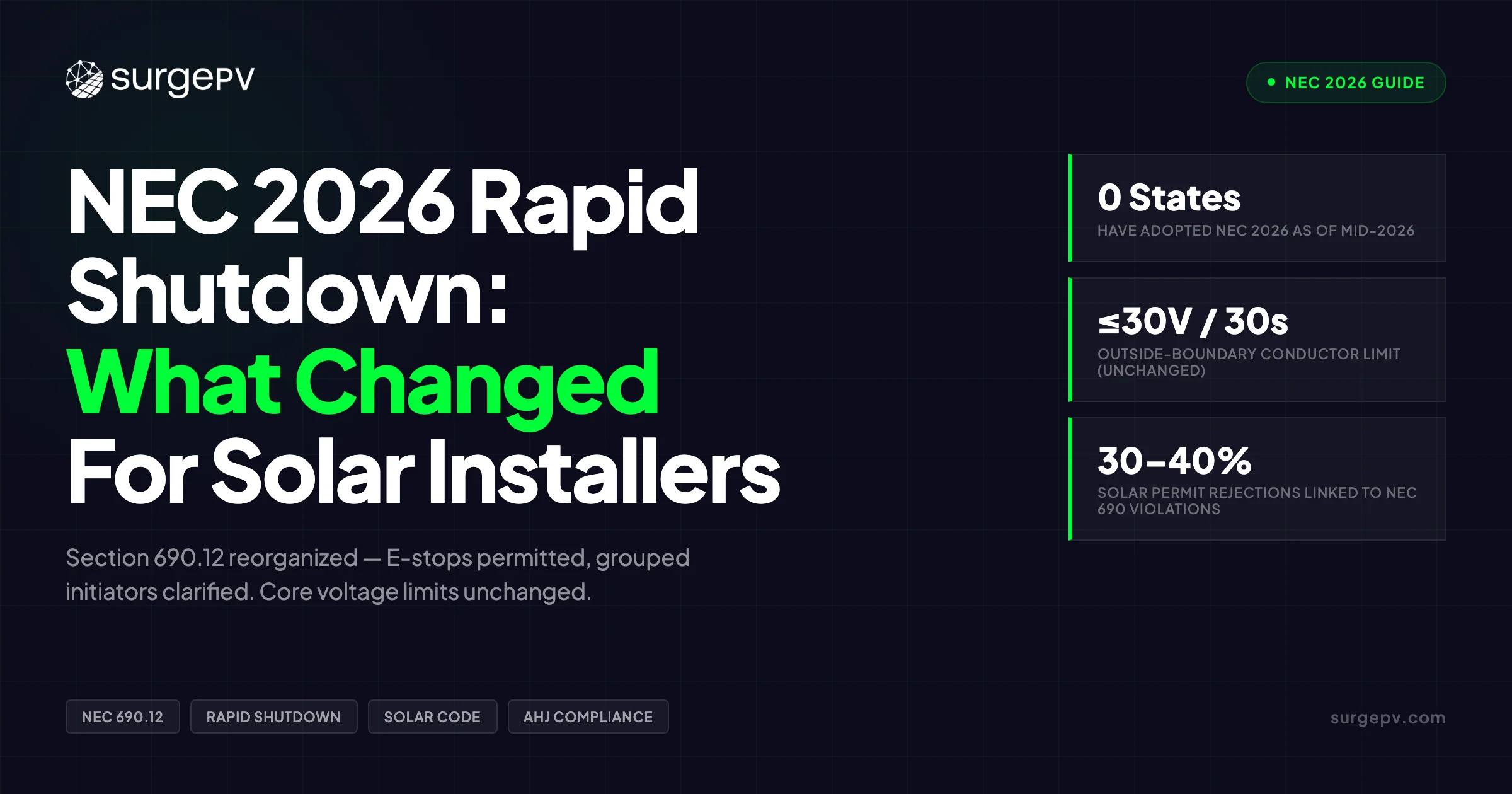
As of May 2026, no U.S. state has adopted NEC 2026. Adoption is split roughly evenly between NEC 2023 and NEC 2020, with a smaller number of states on NEC 2017 or 2008 (PrintProAZ, 2026; BHS1, 2026). Planning now — before your jurisdiction adopts the 2026 edition — is the cheapest time to get it right.
TL;DR
NEC 2026 reorganizes Section 690.12 for clarity but keeps the same voltage limits: outside the array boundary, conductors must drop to ≤30V within 30 seconds; inside, ≤80V or a listed PVHCS within 30 seconds. E-stop switches are now explicitly permitted. No U.S. state has adopted NEC 2026 yet — most adoption is expected between 2027 and 2030.
What this guide covers:
- The exact changes NEC 2026 makes to Section 690.12 vs. 2023 and 2020
- How the array boundary and voltage limits work (outside vs. inside boundary)
- Which MLPE devices and UL 3741 PVHCS systems are compliant today
- When AHJs will start enforcing NEC 2026 by state
- How rapid shutdown affects string sizing, inverter selection, and system cost
- The most common installer mistakes that fail plan review and final inspection
- How to design RSD-compliant systems faster
What Is Rapid Shutdown and Why NEC 690.12 Exists
Rapid shutdown is the code requirement that forces a PV system’s conductors to de-energize when a shutdown signal is triggered. That signal might come from a manual initiator switch, a building fire-alarm panel, or loss of grid power.
The motivation is specific: a firefighter cutting through a roof doesn’t know which wires are hot. Without rapid shutdown, DC conductors on a residential rooftop can hold 300–600V as long as the sun shines — independently of whether the grid is live, the inverter is operating, or the building’s AC breakers have tripped. Standard AC safety protocols don’t apply.
NEC 690.12 first appeared in the 2014 edition. That version required conductors outside a 10-foot boundary from the array to de-energize to ≤30V within 10 seconds. There was no inside-boundary limit. The 2017 edition tightened the boundary to 1 foot in all directions and added an inside-boundary limit of ≤80V within 30 seconds. Each subsequent edition refined the requirements further.
Important Distinction
Rapid shutdown does not stop panels from producing power. Photovoltaic modules continue generating current as long as sunlight hits them. What rapid shutdown does is prevent that current from reaching conductors accessible to first responders — the conductors running from the array through the building and to the inverter.
Understanding this distinction matters for design. Modules remain energized at their open-circuit voltage at the cell level. What changes is whether dangerous current can flow through accessible conductors.
NEC 690.12 Boundary and Voltage Requirements — The Core Rules
The performance requirements at the center of Section 690.12 have not changed since NEC 2017. Understanding them is prerequisite to understanding what NEC 2026 actually modified.
Array Boundary
The array boundary is defined as 305 mm (1 foot) from the array in all directions, including 1 foot above the highest point of a building-mounted array (NEC 690.12, 2026). This 1-foot boundary has been the standard since NEC 2017 and is unchanged in 2026.
For building-mounted systems, this means conductors running more than 1 foot from the array edge — essentially, any wiring inside the building — must meet the outside-boundary requirement.
Voltage Limits by Zone
| Zone | Max Voltage | Timeframe |
|---|---|---|
| Outside array boundary | ≤ 30V | Within 30 seconds |
| Inside array boundary | ≤ 80V OR listed PVHCS | Within 30 seconds |
Voltage is measured between any two conductors and between any conductor and ground. This applies to PV source circuits and output circuits.
What Counts as the Array Boundary?
The 1-foot rule sounds simple but generates real inspection questions. For building-attached structures — a covered deck built against the house wall, a canopy with a structural attachment point — the AHJ determines whether the structure triggers 690.12.
NEC 2023 added Exception No. 2, which exempts non-enclosed detached structures (freestanding carports, shade canopies with no building attachment) from the inside-boundary requirement (SolarBidAnalyzer, 2026). NEC 2026 retains this exception. If you’re designing a carport system and assuming the exception applies, get it in writing from the AHJ before permit submission. Shadow analysis software identifies shading issues before installation.
For rooftop systems, MLPE devices — power optimizers or microinverters — handle the inside-boundary requirement automatically at each module. UL 3741 PVHCS-certified systems achieve the same result at the array level without per-module electronics.
NEC Edition Timeline: 2014 to 2026
To understand where NEC 2026 fits, you need the full picture of how 690.12 evolved. Most guides cover one or two editions. Here is the complete timeline:
| Edition | Key Change |
|---|---|
| NEC 2014 | First rapid shutdown requirement. 10-ft boundary. ≤30V in 10 seconds outside boundary. No inside-boundary limit. |
| NEC 2017 | Boundary reduced to 1 ft. Inside boundary added: ≤80V within 30 seconds. Effective Jan 1, 2019 in most states. |
| NEC 2020 | PV Hazard Control System (PVHCS) introduced under UL 3741. Single initiation device per PV system. |
| NEC 2023 | Added shock hazard control language. Removed BIPV exception. Added Exception No. 2 for non-enclosed detached structures. Placard requirements moved from 690.56(C) to 690.12(D). |
| NEC 2026 | Reorganized 690.12(B) and (C) for clarity. E-stops explicitly permitted. Grouped initiators for up to six systems clarified. No performance target changes. |
Pro Tip
If you’re currently designing to NEC 2020, the 2023 code requires substantial changes — including updated labeling locations and the removal of the BIPV exception. Plan for 2026 labeling language and E-stop compatibility now so you’re not redesigning when your state adopts.
The most significant jump was NEC 2017, which moved from a 10-foot exterior boundary to a 1-foot boundary and added the inside-boundary requirement. That edition forced a complete rethinking of system design for rooftop installs. Every edition since has been refinement.
What Specifically Changed in NEC 2026
NEC 2026 is a clarification cycle, not a performance-target change. The three sections that changed meaningfully are 690.12(B), 690.12(C), and 690.12(D).
Section 690.12(B) — Controlled Conductors (Reorganized)
The 2026 edition reorganizes 690.12(B) to improve clarity on two specific questions: where voltage control must occur, and how shock hazard protection is achieved.
The inside vs. outside boundary distinction is retained exactly as in NEC 2023. The structural change is editorial — the text is now more usable for inspectors and plan reviewers who need to apply the requirements at the permit desk without cross-referencing multiple subsections. Also see: Us Residential Solar Market Trends 2026. For United States-specific compliance details, see United States arizona/phoenix. For United States-specific compliance details, see United States california/los-angeles.
For installers, the underlying design requirements are unchanged. What changes is how AHJs will frame their questions during plan review.
Section 690.12(C) — Initiation Devices (Most Extensively Revised)
This is the section with the most consequential changes in NEC 2026. The requirements are reorganized into three subdivisions:
- Type and Location — which devices qualify as initiation devices and where they must be installed
- Operation — how initiation must function when triggered
- Multiple PV Systems — rules for grouped initiators when multiple PV systems share a building
Two specific changes matter for real installations:
E-stop switches now explicitly permitted. Previous language required switches to “plainly indicate whether they are in the ‘off’ or ‘on’ position.” That wording excluded standard emergency-stop (E-stop) switch designs, which use maintained-push or key-operated mechanisms rather than a visible off/on indicator. NEC 2026 removes this language, explicitly allowing E-stop type switches (ElectricalLicenseRenewal, 2026). This matters for commercial and industrial applications where E-stop hardware is standard safety infrastructure.
Grouped initiators for multiple systems. NEC 2026 clarifies that up to six rapid shutdown initiation devices can operate together to satisfy the requirement for all interconnected PV systems on a building (ElectricalLicenseRenewal, 2026). This is relevant for larger commercial rooftop installations where multiple inverter systems share the same building and previously required separate initiator logic per system.
Outdoor location reinstated for dwellings. TIA 1835 to NEC 2026 reinstated language requiring that for one- and two-family dwellings, initiation devices “shall be located at an outdoor location” (NFPA TIA 1835, 2025). This requirement had been inadvertently deleted during the 2026 revision cycle and was restored via the TIA process.
Section 690.12(D) — Labeling
NEC 2023 moved rapid shutdown placard requirements from 690.56(C) to 690.12(D). NEC 2026 retains this location. The building placard no longer has a specific color mandate in NEC 2023/2026 — only that text must contrast the background — but the rapid shutdown switch label (690.12(D)(2)) still requires a red background with white reflective lettering (Solar Permit Solutions, 2026).
Grandfathering
The applicable NEC edition is the one in force at the time of permit issuance. NEC 2026 does not retroactively require redesign of existing systems. AHJ authority applies — confirm with your local jurisdiction.
For a broader look at all NEC 2026 solar changes beyond Section 690.12, see our NEC 2026 solar changes guide.
Compliance Pathways: MLPE vs. UL 3741 PVHCS
Two pathways achieve compliance with NEC 690.12 for building-mounted systems. Understanding both is necessary for selecting the right approach for each project type.
Module-Level Power Electronics (MLPE)
MLPE is the most common pathway for residential and commercial rooftop installs. Each module has its own power optimizer, microinverter, or dedicated rapid shutdown device. When the initiation signal fires — or when AC power is lost — each module-level device reduces its output to ≤1V within 30 seconds.
MLPE systems achieve inside-boundary compliance automatically, since the shutdown happens at the module level. There are no conductors between modules carrying dangerous voltages after initiation.
Pros: Compatible with virtually all racking systems; per-module monitoring; shade tolerance (especially with power optimizers and microinverters); straightforward inspection.
Cons: Additional BOS cost ($0.10–$0.40/W depending on device type); more DC connection points (more potential failure locations); heat exposure for module-mounted electronics.
UL 3741 PV Hazard Control System (PVHCS)
The UL 3741 pathway certifies a racking + inverter combination as a complete system. Rather than de-energizing at the module level, the system achieves safe touch voltages across the entire array through the certified combination’s design.
This approach requires no per-module electronics. A string inverter paired with a UL 3741-certified racking system can meet inside-boundary requirements without adding optimizers or microinverters to each panel.
Pros: BOS cost reduction up to 20% vs. per-module MLPE; fewer components; simpler wiring.
Cons: Limited number of certified combinations; less per-module monitoring granularity; less effective in shade conditions.
| Factor | MLPE | UL 3741 PVHCS |
|---|---|---|
| Per-module electronics | Required | Not required |
| BOS cost premium | $0.10–$0.40/W | $0.05–$0.15/W |
| Shade tolerance | High (optimizers/microinverters) | Low–moderate |
| Monitoring granularity | Per module | System level |
| Compatible inverters | Device-specific | Certified combinations only |
| Design complexity | Moderate | Low (if using certified combo) |
For NEC Article 690 context beyond rapid shutdown, that glossary entry covers the full article scope.
Compliant Rapid Shutdown Devices by Manufacturer
Rapid shutdown hardware selection depends on your inverter ecosystem, module wattage, and whether you’re doing a new install or retrofit. Here is the current device breakdown:
SolarEdge — Power Optimizers (P850, P950, P1100, S440, S500B) with built-in SafeDC rapid shutdown. Automatically reduces module voltage when the inverter or grid shuts down. SolarEdge optimizers only function with SolarEdge inverters — there is no cross-brand compatibility.
Enphase — IQ8 Series microinverters are inherently compliant. No additional RSD hardware is required. AC power loss shuts down each module individually. Enphase eliminates string sizing calculations since each module operates independently.
Tigo Energy — Multiple devices covering different use cases:
- TS4-A-F: Single module input, dedicated fire safety RSD
- TS4-A-2F: Dual module inputs, no ground wire required
- TS4-A-S: RSD + monitoring
- TS4-A-O: RSD + optimization + monitoring
Tigo devices work with a broad inverter ecosystem — SMA, Fronius, Sol-Ark, and others — via SunSpec protocol or Tigo RSS Transmitter.
SMA Solar Technology — JMS-F (420 W, 60 V, 15 A) and JMS-F-V2 (600 W, 60 V, 15 A) SunSpec Rapid Shutdown Modules. Use powerline communication (PLC) over existing DC wiring. Up to 50% fewer internal components than comparable alternatives. Note: the original JMS-F is not compatible with SMA Sunny Boy Smart Energy (SBSE-xx-US-50) or Tripower X-US-50 inverters; use JMS-F-V2 for newer inverter models (Solar-Electric, 2026).
APsystems — RSD-S-PLC: SunSpec PLC module-level RSD. Max 80 V, 15 A. Compatible with SMA and other SunSpec inverters (SunWatts, 2026).
IMO Automation — FireRaptor: Solid-state switch requiring no powerline communications. 20-year warranty. Compatible with all inverter types, making it a flexible retrofit option. Can integrate temperature-sensing for auto-shutdown at >85°C (IMO Automation, 2026).
Fronius — Primo, Symo, and GEN24 series inverters paired with Tigo TS4-F or TS4-A-O for module-level compliance.
| Manufacturer | Device | Technology | Inverter Compatibility | NEC Editions |
|---|---|---|---|---|
| SolarEdge | P1100 / S500B | SafeDC optimizer | SolarEdge only | 2014–2026 |
| Enphase | IQ8 Series | Microinverter | N/A (self-contained) | 2014–2026 |
| Tigo | TS4-A-F / TS4-A-O | SunSpec or Tigo RSS | SMA, Fronius, Sol-Ark, others | 2014–2026 |
| SMA | JMS-F / JMS-F-V2 | SunSpec PLC | SMA SunSpec certified | 2017–2026 |
| APsystems | RSD-S-PLC | SunSpec PLC | SMA + other SunSpec | 2017–2026 |
| IMO Automation | FireRaptor | Solid-state | All types | 2014–2026 |
Pro Tip
Verify SunSpec compatibility before mixing brands. A Tigo TS4-A-F on a SolarEdge inverter will not function — SolarEdge requires its own optimizer ecosystem. Cross-check inverter compatibility lists before purchase, especially on retrofit jobs where the inverter is already installed.
Design RSD-Compliant Solar Systems in Minutes
SurgePV auto-flags rapid shutdown requirements based on your AHJ, generates permit-ready one-line diagrams, and produces full equipment schedules — including RSD placement and label locations.
Book a DemoNo commitment required · 20 minutes · Live project walkthrough
For a direct comparison, see Arka 360 vs SurgePV.
AHJ Enforcement Timelines — When NEC 2026 Becomes Law
As of May 2026, no U.S. state has adopted NEC 2026. Adoption requires state legislation or regulatory action — the NFPA publishes the code, but each state independently decides when to enforce it.
Current state breakdown (PrintProAZ, 2026; CodeCheck, 2026):
- Approximately 25 states enforce NEC 2023
- Approximately 13–15 states enforce NEC 2020
- A handful of states remain on NEC 2017 or 2008
- Several states (e.g., Arizona, Illinois, Mississippi, Missouri) have no statewide adoption, leaving enforcement to local jurisdictions
| State / Region | Expected Adoption | Notes |
|---|---|---|
| Washington | 2026 | Statewide update scheduled for 2026 (CodeCheck, 2026) |
| Oregon | 2027 (est.) | Typically 12–18 months after NFPA release |
| Most other states | 2027–2030 | Varies widely by state regulatory process |
| California | Adopted NEC 2023 | Title 24, Part 3 with CEC amendments (CodeCheck, 2026) |
| Local-jurisdiction states (AZ, NV, IL) | Varies by city/county | Individual jurisdictions may enforce different editions than the state |
AHJ adoption timelines have real design implications. A system permitted in 2026 in Washington will need to comply with NEC 2026. The same system permitted in California falls under NEC 2023. Design tools that track AHJ-specific code editions eliminate this guesswork.
Always Verify
Confirm the applicable NEC edition with your local AHJ before starting permit drawings. Using NEC 2023 labels in an NEC 2020 jurisdiction — or vice versa — can fail inspection at the final walk-through, requiring costly label replacement and re-inspection scheduling.
Grandfathering generally applies to systems installed before local adoption. If a substantial modification occurs — a roof replacement that requires pulling panels, an inverter swap that triggers re-permitting — the AHJ may require upgrading to the current edition. Confirm with the local jurisdiction before starting any modification work.
Good solar designing tools flag which edition applies per project location and document the basis for design in the permit package.
How Rapid Shutdown Affects System Design
Rapid shutdown requirements influence system design at every level — from string sizing calculations to inverter selection to fire-alarm integration. Getting this wrong at the design stage creates rework.
String Sizing with RSD Constraints
String sizing for RSD-compliant systems follows the same NEC 690.7 temperature-correction rules as any PV system, but RSD device voltage windows add an additional constraint layer.
For string inverter + dedicated RSD systems:
- String Voc × temperature correction factor must stay within the inverter’s maximum input voltage
- Temperature correction: NEC 690.7 requires using the lowest expected ambient temperature at the site (ASHRAE or equivalent climate data), not a fixed multiplier. Many designers apply a 1.25 factor as a conservative shortcut for cold climates, but the code mandates calculation from actual site data.
- Example: 480W panels, Voc 49.5V × 1.25 = 61.875V; 600V inverter ÷ 61.875V = 9.7 panels max → practical string size of 9 panels
For power optimizer systems, each optimizer has its own input voltage range. The SolarEdge P1100, for example, accepts 12.5V–105V at the module input. Verify each module’s operating voltage falls within the optimizer’s range — especially for high-wattage bifacial panels where Voc can approach the upper limit. See Bifacial Solar Panel Design Guide for detailed guidance.
Microinverter systems eliminate string sizing constraints entirely. Each module operates independently through its own grid-tied inverter.
Inverter Selection and RSD Compatibility
| Inverter Type | RSD Approach | String Sizing Required |
|---|---|---|
| SolarEdge with optimizers | SafeDC built-in | Yes — per NEC 690.7 |
| Enphase IQ8 microinverters | Inherently compliant | No |
| SMA / Fronius + Tigo TS4 | SunSpec PLC | Yes — per NEC 690.7 |
| String inverter + UL 3741 system | Array-level PVHCS | Yes — per NEC 690.7 |
UL 3741 certified combinations allow traditional string inverter use without per-module electronics, reducing BOS costs by up to 20% (SunPalsSolar, 2026). The tradeoff is a limited pool of certified inverter + racking combinations and no per-module monitoring.
DC/AC Ratio Guidance
- Commercial systems: 1.10–1.25 DC/AC ratio
- Residential with high-wattage panels: 1.2–1.3
Oversizing the array relative to the inverter maximizes inverter utilization during non-peak hours while accepting modest clipping at peak irradiance. This is unchanged by rapid shutdown requirements but affects total system output used in financial modeling.
Use the generation and financial tool to model output and payback periods across different string configurations and DC/AC ratios.
Fire-Alarm Integration
For commercial systems, the rapid shutdown initiator is often wired to the building’s fire-alarm control panel (FACP). A fire alarm event automatically de-energizes the array without manual action. This integration must appear on both the electrical drawings and the fire-alarm riser diagrams.
IFC Section 605.11 (and IRC R324.6 in residential) requires roof access pathways and setbacks — coordinate these with the RSD device placement map so that access pathways don’t conflict with initiator wiring runs. Residential requirements include 36-inch pathways from eave to ridge and ridge setbacks of 18 inches (≤33% roof coverage) or 36 inches (>33% coverage) (SolarBidAnalyzer, 2026).
Common Installer Mistakes That Fail Inspection
NEC 690 permit violations account for approximately 30–40% of all solar permitting rejections nationwide (EnergyScape Renewables, 2026). Rapid shutdown issues are among the most common triggers.
| Mistake | Result | Fix |
|---|---|---|
| String inverter without integrated RSI or separate RSD | Fails plan review | Add SunSpec RSD or switch to MLPE |
| RSI installed inside locked electrical room | Fails inspection — not readily accessible | Install at utility meter or exterior location |
| Missing or wrong labels | Fails final inspection | Order pre-printed 690.12(D) labels before install |
| Incompatible optimizer + RSI combination | System malfunction during shutdown | Verify SunSpec compatibility before purchase |
| Building-attached carport treated as ground mount | Code violation | Confirm attachment status with AHJ before design |
| Improper DC connectors or crimping | Arc faults, fire risk | Use manufacturer-specified tools and matching connectors |
The three mistakes that appear most frequently in failed inspections:
String inverter without an RSI. A plain string inverter does not inherently comply with 690.12 for inside-boundary conductors. Adding a SunSpec-compatible RSD to each module — or switching to an MLPE architecture — is required. This is sometimes caught at plan review but often missed until final inspection.
RSI in a locked room. “Readily accessible” means accessible to first responders without tools. An RSI in a locked utility room behind a keypad fails this requirement. Install the initiator at the utility meter or another permanently accessible exterior location. For dwellings, NEC 2026 (via TIA 1835) explicitly requires the initiator to be at an outdoor location.
Wrong labels. NEC 2023 moved placard requirements from 690.56(C) to 690.12(D). Inspectors in NEC 2023 jurisdictions look for labels in specific locations. A placard from a pre-printed 2020 label set may reference the wrong section or omit required elements. The building placard color requirement was also relaxed in NEC 2023, but the switch label still requires red background with white reflective lettering.
Label Planning
Plan label placement at the design stage. Retrofitting label locations after install — cutting new holes in conduit for label wells, repositioning initiator signage — is expensive and often requires re-inspection scheduling.
Nuisance Tripping — Causes and Fixes
A system that trips its rapid shutdown circuit unnecessarily creates callbacks, frustrated customers, and potential safety gaps. Nuisance tripping in RSD systems has three main causes.
AFCI interference. Arc Fault Circuit Interrupter algorithms can misread electrical noise from optimizer switching frequencies as arc signatures. The result is nuisance tripping — or, worse, a failure to detect real arcs. Confirm AFCI firmware compatibility with the optimizer manufacturer before finalizing the design.
Switching noise from RSDs. RSDs and power optimizers generate electrical noise that raises DC-side noise levels. In dense installations, this noise can interfere with the shutdown signal itself — a particularly acute problem with SunSpec PLC systems where the control signal travels over the same DC conductors carrying the noise.
Moisture-related ground faults. Moisture ingress into MC4 connectors or junction boxes causes transient ground faults. Industry data shows moisture-related ground faults account for approximately 70% of inverter nuisance trips in high-humidity regions (Boston Solar, 2026).
Field troubleshooting checklist:
- Inspect MC4 connectors for proper torque and manufacturer-matched crimps
- Check junction boxes for moisture ingress and verify IP rating for the installation environment
- Verify SunSpec PLC signal strength (especially with SMA JMS-F and Tigo systems on long string runs)
- Confirm AFCI firmware version with the inverter manufacturer
- Test the RSI location for signal interference from nearby electrical equipment
The safety data from nuisance-tripping research reinforces why hardware quality matters. HelioVolta’s analysis of commercial rooftop systems (March 2026) identified 74 high-risk safety incidents involving RSDs between 2021 and early 2026 — including 40 instances of RSDs melting or overheating and 21 rooftop fires linked to RSD failures (PV Magazine USA, 2026; Solar Builder, 2026).
Device Quality
Not all RSDs carry equivalent field reliability. Specify UL-listed devices with documented warranty terms and a verified installation base. The $0.02/W savings on an off-brand RSD is not worth a callback, a failed inspection, or a warranty claim.
Designing RSD-Compliant Systems Faster
Rapid shutdown compliance adds steps to every project: confirming the applicable NEC edition, sizing strings within RSD voltage windows, placing labels correctly, and generating permit documentation that shows initiator location.
Solar design software that integrates code compliance reduces this to a set of automated checks. Three specific points in the design workflow where software removes manual risk:
1. AHJ-aware code flagging. The design tool identifies which NEC edition applies to your permit jurisdiction and flags the specific 690.12 requirements that apply — inside-boundary, outside-boundary, initiator type, and label placement locations. No manual lookup required.
2. String sizing with temperature correction. Automated NEC 690.7 temperature correction per site location generates the maximum string length, accounting for both inverter input voltage limits and optimizer voltage windows. The calculation is documented and print-ready for plan review.
3. Permit-ready documentation. One-line diagrams, equipment schedules with RSD model numbers, and label placement maps are generated from the same design file. No transcription errors between design and permit package.
Solar software that handles these three steps consistently reduces per-permit time and lowers the risk of inspection failure on rapid-shutdown-related items.
For customer-facing work, solar proposal software that integrates system specifications with compliance documentation makes it easier to show clients exactly what equipment is being installed and why — including the rapid shutdown devices that affect their system’s safety and monitoring capabilities.
See How SurgePV Handles Rapid Shutdown Compliance
From AHJ-aware string sizing to permit-ready documentation, SurgePV removes the guesswork from NEC compliance on every project.
Book a DemoNo commitment required · 20 minutes · Live project walkthrough
Frequently Asked Questions
What did NEC 2026 change about rapid shutdown compared to NEC 2023?
NEC 2026 reorganizes Section 690.12 for clarity but does not change core performance targets. The main changes: E-stop switches are now explicitly permitted as initiation devices, grouped initiators for up to six PV systems are clarified, and the outdoor location requirement for dwelling initiators was reinstated via TIA 1835. No performance voltage or timing requirements changed.
Are ground-mounted solar systems exempt from rapid shutdown?
Ground mounts on non-enclosed, detached structures such as carports and canopies may qualify for Exception No. 2, added in NEC 2023 and retained in 2026. Building-attached structures trigger 690.12. AHJ confirmation is required — local enforcement varies, and the AHJ has final authority. For more on this topic, see Commercial Solar Carport Design Guide.
Do microinverters comply with NEC 690.12 rapid shutdown?
Yes. Microinverters such as Enphase IQ8 are inherently compliant. When AC power or the initiation signal is lost, each module shuts down individually. No additional RSD hardware is required for microinverter-based systems.
Where must the rapid shutdown initiator be located?
The initiator must be readily accessible. For one- and two-family dwellings, NEC 2026 (via TIA 1835) requires initiation devices to be located at an outdoor location. Common AHJ interpretation places the initiator at the utility meter or another exterior location accessible to first responders — not inside a locked electrical room.
How much does rapid shutdown add to system cost?
Cost depends on technology: dedicated RSDs add $0.05–$0.20/W; power optimizers $0.10–$0.30/W; microinverters $0.20–$0.40/W (SunPalsSolar, 2026). UL 3741 PVHCS systems can reduce overall BOS cost by up to 20% compared to per-module MLPE approaches.
Can rapid shutdown be retrofitted to an older solar system?
Yes — dedicated RSDs from manufacturers like Tigo (TS4-A-F) and IMO Automation (FireRaptor) can be added to existing string inverter systems. Verify that the inverter supports the required communication protocol (SunSpec PLC or Tigo RSS) before purchasing devices.