One wrong string calculation—and suddenly your inverter is clipping, or worse, the system shuts down.
In solar design, precision isn’t just ideal—it’s mandatory. Mistakes in string sizing can cascade into underperformance, safety failures, equipment damage, and warranty voids. From unexpected voltage spikes in winter to inverter mismatch errors, these design flaws are often invisible—until the system fails.
A 0.2A overcurrent on a cloudy day? That’s how systems fry, contracts break, and clients churn.
This guide breaks down the most common solar string design mistakes, backed by engineering logic—and shows how modern tools can help you avoid them entirely.
Why String Sizing Is So Critical in Solar Design
String sizing is the spine of solar system performance. Each string determines how current and voltage flow to the inverter—meaning a wrong config can trip the system, void warranties, or cut annual yield by double digits.
The key variables—Voc, Vmp, Vmax, and MPPT window—must be balanced precisely, and aligned to module specs, inverter tolerances, and extreme temperature scenarios.
Let’s break down the design logic and where most EPCs stumble.
Role of Vmax, Vmp, and Voc in String Planning
These three values define the voltage range you must plan within:
- Voc (Open Circuit Voltage) is the highest possible voltage a module can produce—especially in cold weather.
- Vmp (Maximum Power Voltage) is where the module operates efficiently most of the time.
- Vmax is the inverter's ceiling—exceed it, and the inverter may clip, disconnect, or even fail.
The trick? Your Voc (cold) must never exceed Vmax, and your Vmp must align with the MPPT window of the inverter.
Safety Margins for Cold Weather (Voltage Creep)
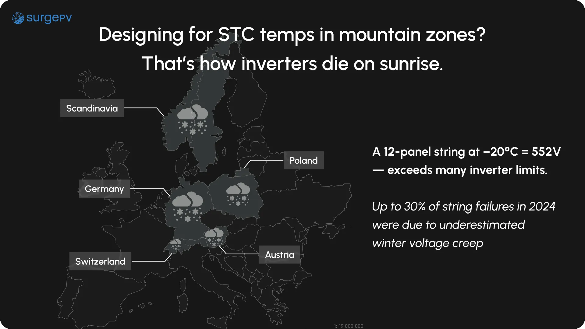
Cold temperatures increase voltage. In northern Europe or mountain zones, winter mornings can push Voc well above the standard test conditions (STC) values. If not sized correctly, this spike can breach the inverter’s voltage limit.
Designers must account for temperature-induced voltage creep by applying correction factors, often between +10% to +15%, based on lowest expected temperatures.
Formula – Voc-cold = Voc × [1 + (Temp Coefficient × ΔT)]
This simple formula helps you calculate real-world Voc in cold conditions:
Voc-cold = Voc × [1 + (β × ΔT)]
Where:
- Voc = module open-circuit voltage
- β = temperature coefficient (typically ~–0.0035/°C)
- ΔT = difference between STC temp (25°C) and lowest site temp
Example:
Voc = 40V, β = –0.0035, Min Temp = –10°C
ΔT = –35 → Voc-cold = 40 × [1 + (–0.0035 × –35)] ≈ 44.9V
Multiply that across a string of 10 modules = 449V at startup, before the sun even rises.
Common Tolerances Required by Inverter OEMs
Inverter datasheets often specify:
- Absolute Max Input Voltage (Vabs): e.g., 1,000V
- Recommended Voc Margin: 5–10% buffer
- MPPT Window Range: e.g., 300–850V
Designers must not only avoid exceeding Vabs—but ensure Vmp at operating temps lands inside the MPPT window.
Failure to meet these tolerances can cause inverter shutdowns, string underutilization, or persistent efficiency loss—one of the most expensive PV wiring mistakes long-term.
Mistake #1 – Ignoring Temperature Extremes
One of the most common and costly string sizing errors is assuming average temperature instead of planning for extremes. While modules are rated at 25°C (STC), real-world voltages spike in cold and dip in heat.
In alpine regions or Northern Europe, subzero temperatures cause Voc to creep up, often surpassing inverter limits. And in hot southern zones, under-voltage can push Vmp out of the MPPT window.
Designing without weather-adjusted voltage modeling invites warranty voids, inverter faults, and system downtime.
What Happens When Voc Exceeds Inverter Max

When the Voc at site temperature exceeds the inverter’s absolute voltage limit:
- The inverter may refuse to start (cold mornings = no generation)
- Long-term damage risk increases, voiding warranties
- Voltage surge protection devices (SPD) may trip unnecessarily
- Daily system resets and error codes can wear out monitoring teams
In real terms, this means a full string is online—but producing nothing, often during peak irradiance in winter.
Min/Max Temp Assumptions by Region
Before you size strings, always validate:
- Min design temp (from historical weather data, not forecast)
- Use 10-year lows in mountain/high-altitude zones
- Reference EU or national PV installation codes (e.g., CEI 82-25)
- Use delta from 25°C STC, not ambient operating temp
- If unsure, apply a 15% Voc buffer for northern or inland zones
Skipping these steps is one of the most silent but deadly PV wiring mistakes.
Voc Derating vs Winter Temperature
Using nominal values here leads to undetected inverter voltage overruns—especially in hybrid systems.
Bonus Tip – How to Size for Mountain vs Coastal Zones
In mountain zones:
- Use higher correction factors (+12–15%)
- Favor shorter strings or inverters with wider MPPT input ranges
- Always check for early morning startup voltage compatibility
In coastal/hot zones:
- Watch for low Vmp drift (underproduction in summer)
- Consider optimizers or modules with better thermal coefficients
Location isn’t just a backdrop—it’s an electrical variable.
Mistake #2 – Mismatch Between Modules and Inverter Input Windows
Even with perfectly calculated string voltages, mismatch between array characteristics and inverter MPPT windows is a silent killer of efficiency. If your Vmp doesn’t sit inside the inverter’s tracking range for most of the day, you’re leaving energy on the table.
Worse, if startup voltage isn’t met on cloudy or cold days, the system won’t even wake up.
Here’s how most designers get it wrong—and what to double-check.
Not All Inverters Handle Low Light or Partial Strings
Some inverters require a minimum threshold voltage just to initiate MPPT tracking. In scenarios with low irradiance or partial shading:
- Inverters may fail to start up
- Strings may fall outside tracking range
- Lower output across the entire day (not just low-light periods)
Choosing modules with lower Vmp or longer strings can help—but only if that doesn’t push Voc too high in cold.
What to Check in Inverter Datasheets
- MPPT window range (e.g., 350V–800V)
- Startup voltage (usually 125–350V)
- Absolute max voltage (Vmax) tolerance
- Number of MPPTs and string count per MPPT
- Recommended DC/AC ratio
- Support for asymmetrical stringing
One missed detail here can result in a string design that works on paper—but fails in real conditions.
Symmetrical Strings vs Uneven Dual MPPT Inputs
Some inverters allow different string lengths across MPPTs. Others demand symmetry. Mismatching Vmp across trackers can:
- Trigger balancing losses
- Cause one tracker to pull down the other
- Reduce inverter efficiency by 5–10%
Designs with complex roof layouts or partial shading should use independent MPPTs—and carefully align string lengths and orientations per input.
Using DC/AC Ratio Logic to Guide String Count
String count isn’t just about voltage—it’s about energy input relative to inverter size.
- A DC/AC ratio of 1.1–1.3 is common in residential systems
- Oversizing beyond 1.35 can cause clipping
- Undersizing below 1.0 may lead to underutilization
Use this ratio to back-calculate ideal string count per inverter, especially when mixing module wattages or tilts.
Mistake #3 – Overlooking Shade and Orientation Variance
A perfectly calculated string can still perform terribly—if shading or azimuth misalignment isn’t considered. Even partial shade on one panel can drop current across the entire string, and if one row faces southwest while the other faces southeast, mismatched irradiation levels will sabotage yield.
Ignoring these factors leads to real-world underperformance, even when specs look great on paper.
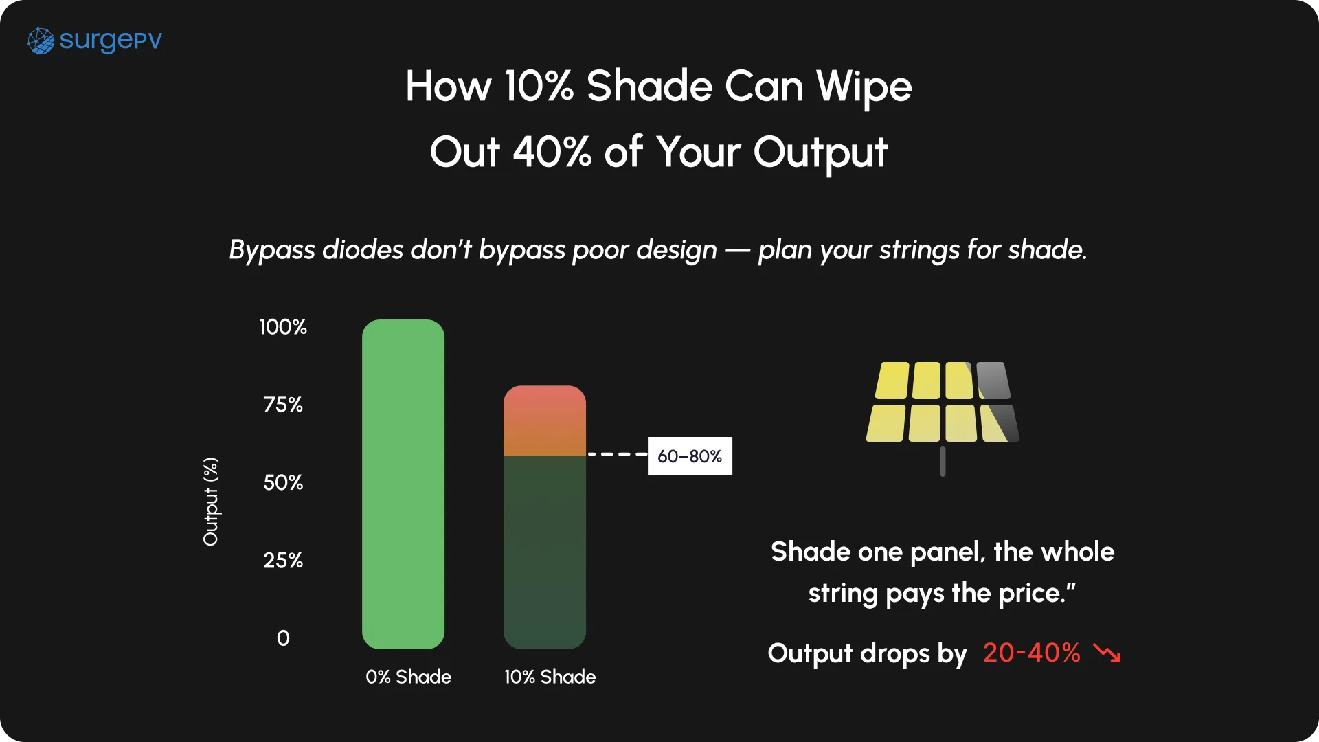
Bypass Diodes ≠ Full Shade Immunity
Many assume that bypass diodes will “fix” string shading. They don’t. They’re only designed to protect modules—not maintain output.
When one panel is shaded:
- Its bypass diode activates, reducing that section’s voltage
- The entire string current drops to the weakest point
- Efficiency loss can reach 30–50% in partial shading zones
Designers must plan for shade-aware stringing, not rely on panel internals.
When to Split Strings by Azimuth or Tilt
If arrays are mounted on surfaces with different:
- Azimuth angles (e.g., east vs west)
- Tilt angles (e.g., flat roof vs 30° pitch)
…they should never share a string. Differently oriented panels produce non-uniform current, which ruins inverter MPPT efficiency.
Split these surfaces into separate strings, ideally with independent MPPTs or power optimizers if mismatches can’t be avoided.
Impact of Shading on IV Curve and Clipping Loss

Shade alters the IV curve, making it jagged and irregular. Inverters struggle to track the Maximum Power Point, resulting in:
- Power tracking errors
- False clipping due to unexpected low-voltage dips
- Reduced average energy output over time
Even 10% daily shading can reduce yield by 15–20% annually if not addressed at the stringing stage.
How to Avoid These Mistakes with Better Tools and Checks
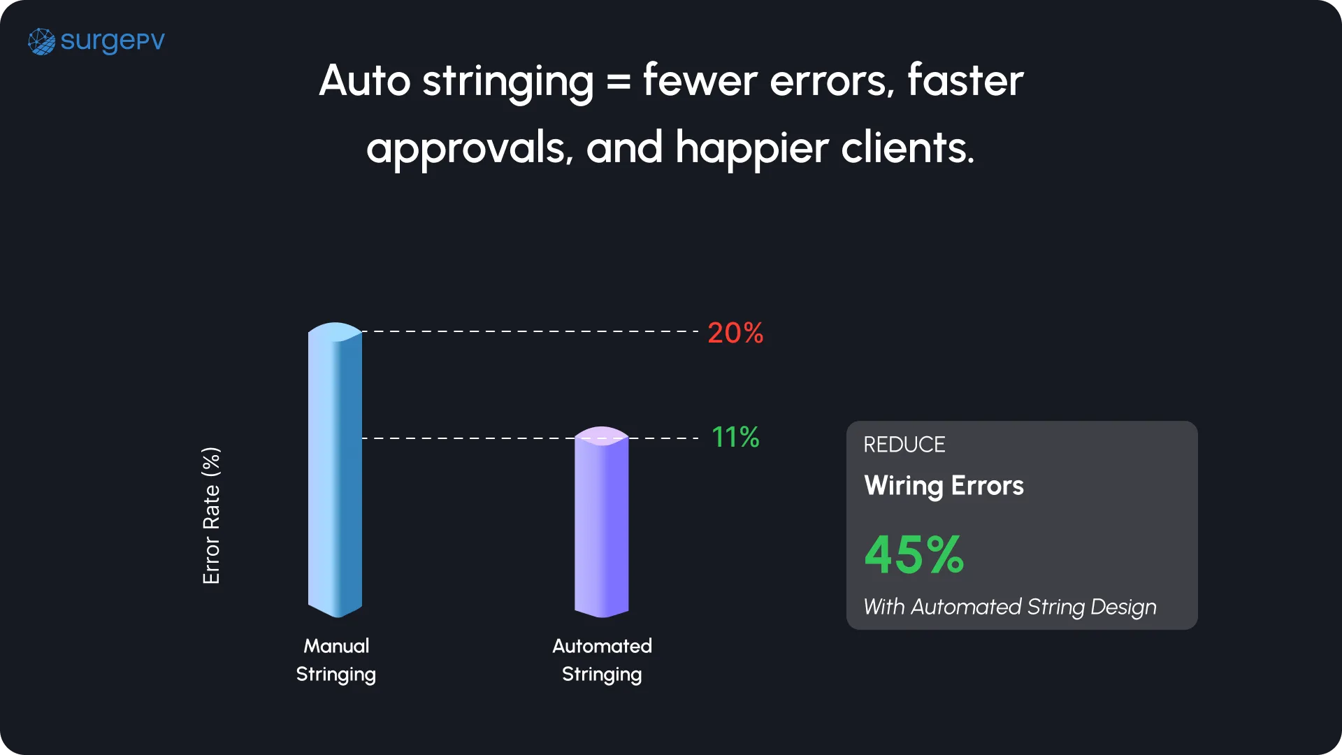
String sizing isn’t just a math problem—it’s an orchestration of variables: modules, inverters, climate, and site constraints. Designing strings without integrated checks, live inverter logic, or layout visualization almost guarantees PV wiring mistakes.
To consistently deliver accurate, fault-free systems, designers need smart tooling. Here’s how to eliminate guesswork.
SurgePV’s Auto-stringing Engine with Voltage/Window Compliance Checks + Instant Single-Line Diagram (SLD) Generation

SurgePV simplifies the entire string design workflow:
- Auto-detects inverter window, module specs, and site temperature
- Runs compliance logic in real time (Voc/Vmp vs MPPT range)
- Applies auto stringing software logic with tolerances built in
- Instantly outputs SLD drawings based on electrical layout
With SurgePV, string design isn’t trial-and-error—it’s precision-built for your conditions.
Visual Heat Maps for String Layout Optimization
Leading tools now offer thermal and irradiance heatmaps over roof surfaces to:
- Suggest ideal string separation
- Avoid high-shade zones
- Optimize tilt vs azimuth groupings
Designers can see performance risk before wiring—avoiding the hindsight trap post-installation.
QA Checklist Before Finalizing String Plan
Before exporting your layout:
- Validate temperature-corrected Voc < inverter Vmax
- Confirm Vmp sits inside MPPT window
- Run shade simulation (hourly, if possible)
- Check module-to-inverter compatibility
- Generate & review SLD (with surge protection + ground paths)
- Validate symmetrical MPPT strings (if required)
No SLD, no submission. No checks, no commissioning.
Top 3 Tools Designers Use in 2025 for Zero-Error Wiring Plans
- SurgePV – Auto stringing + built-in SLDs + compliance alerts
- Helioscope – Good for early-stage string layout experimentation
- PVcase Electrical – Preferred by utility-scale designers for advanced export formats
Most modern EPCs use two tools in tandem: one for layout precision, and one for detailed electrical documentation.
Conclusion
From voltage creep in winter to MPPT mismatch and shade-induced IV distortion, solar string design mistakes can turn a high-efficiency system into a performance liability. These issues aren’t rare—they’re systemic when teams rely on manual sizing or overlook site-specific variables.
But in 2025, automation and precision tools offer a smarter path. EPCs that embed logic-based stringing, live inverter matching, and instant SLD generation avoid rework, protect warranties, and build trust.
Switch to intelligent platforms like SurgePV—the auto stringing solution that helps eliminate design errors before they cost you the project.
FAQs – String Design and Wiring Mistakes
Q1: What is the most common mistake in string design?
Sizing strings based on average temperatures without correcting for winter Voc spikes is one of the most frequent—and dangerous—mistakes.
Q2: Why does MPPT mismatch cause losses?
If Vmp is outside the MPPT window for too long, the inverter can’t track power efficiently, leading to energy losses and increased system downtime.
Q3: Can bypass diodes fix partial shading?
No. Bypass diodes protect the module but don’t prevent power loss. Shaded panels still drag down the whole string unless design addresses orientation.
Q4: What is SurgePV’s role in string design?
SurgePV offers auto stringing software with real-time compliance checks, live inverter matching, and instant single-line diagram (SLD) generation, ensuring every design is both efficient and fault-proof.
Q5: How do I prevent mismatched string performance?
Always separate strings by azimuth/tilt, validate temperature-adjusted Voc, and run shadow analysis using tools like SurgePV, PVsyst, or Helioscope.


