Quick Answer
A 250-bed acute care hospital uses more electricity in a single hour than 60 typical homes use in a day. Article 517 supersedes Article 690 and Article 705. The EES has its own redundancy, transfer time, and power source rules that constrain how solar can interconnect. 2.
A 250-bed acute care hospital uses more electricity in a single hour than 60 typical homes use in a day. It is also the most regulated electrical environment most engineers will ever design for — governed by NEC Article 517, NFPA 99, NFPA 110, Joint Commission standards, state Department of Health rules, and CMS Conditions of Participation. Adding solar to this stack is not a matter of “drop in a 1 MW array and net meter the savings.” Hospital solar system design starts with critical load classification and ends with a documented coordination study that proves the PV system never compromises the Essential Electrical System. This guide walks through every step.
A 250-bed acute care hospital uses more electricity in a single hour than 60 typical homes use in a day. Article 517 supersedes Article 690 and Article 705. The EES has its own redundancy, transfer time, and power source rules that constrain how solar can interconnect. 2.
TL;DR — Hospital Solar System Design
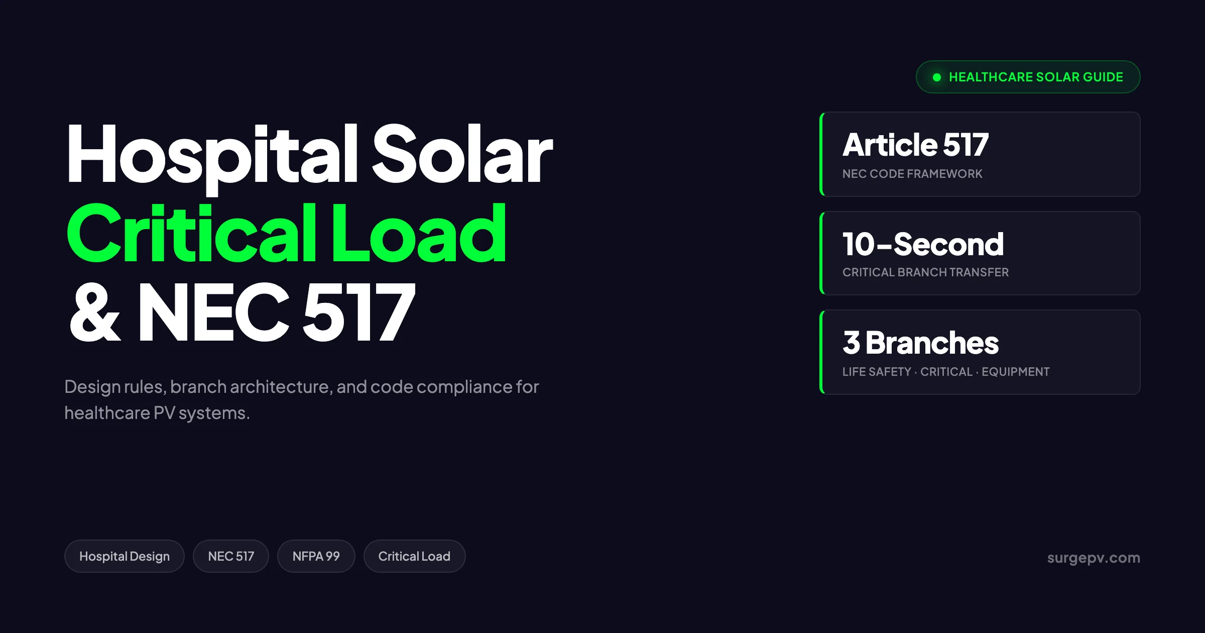
Hospital solar must be designed inside the constraints of NEC Article 517, NFPA 99 risk categories, and NFPA 110 alternate power rules. Solar PV cannot replace the on-site generator required by NEC 517.30(B)(2), but it can serve as a parallel source under NEC 517.30(B)(6) and offset 25–40% of annual energy on a typical site. Critical load identification, 10-second transfer coordination, and microgrid architecture are the three engineering decisions that separate a clean hospital solar project from a permit denial.
Why Hospital Solar Design Is Different From Other Commercial Projects
A hospital is a tier-one mission critical facility. Power loss in a Critical Branch space — an operating room mid-procedure, an ICU ventilator, an isolated power system in a wet location — kills people. That single fact reshapes every design decision compared with a standard commercial solar design software workflow.
Three structural differences matter most:
- Article 517 supersedes Article 690 and Article 705. Hospital electrical systems are split into the Normal Power System and the Essential Electrical System (EES). The EES has its own redundancy, transfer time, and power source rules that constrain how solar can interconnect.
- NFPA 99 risk categories drive load priorities. A pediatric oncology infusion room is Category 1. An administrative hallway is Category 4. Solar plus storage architecture must match the highest category served by each branch.
- The Joint Commission and CMS will audit your work. Joint Commission’s Environment of Care chapter (EC.02.05.03 through EC.02.05.07) audits emergency power systems on every triennial survey. CMS conditions of participation make compliance a Medicare reimbursement requirement, not just a code matter.
A typical commercial rooftop project takes 8–14 weeks from design to PTO. A hospital project takes 9–18 months. The extra time goes into critical load analysis, coordination study, AHJ and Department of Health permitting, and Joint Commission readiness documentation.
NEC Article 517: Health Care Facility Classifications
NEC 517.30(A) classifies healthcare facilities into three Essential Electrical System types. The classification determines the solar designer’s full scope of work.
| EES Type | Facility Examples | Branches Required | Transfer Time | Generator Required |
|---|---|---|---|---|
| Type 1 | General hospitals, large acute care, surgical centers with critical care | Life Safety + Critical + Equipment | 10 seconds (LS, CB) | Yes — on-site |
| Type 2 | Nursing homes, limited care facilities | Life Safety + Equipment | 10 seconds (LS) | Yes — on-site |
| Type 3 | Ambulatory care, urgent care, outpatient surgery (no overnight stays) | Single essential branch | 10 seconds | Generator or battery system permitted |
Type 1 hospitals carry the heaviest design burden. The full Type 1 EES has three branches:
- Life Safety Branch (NEC 517.32): Egress lighting, exit signs, fire alarm system, generator set accessories, communication systems for life safety, automatic transfer switch alarms, and elevators where required.
- Critical Branch (NEC 517.33): Task lighting and selected receptacles in patient care spaces, isolated power systems in anesthetizing locations, nurse call, blood and tissue banks, and selected dialysis equipment.
- Equipment Branch (NEC 517.34): HVAC for operating rooms and intensive care, sterilizers, kitchens, laundry equipment, central suction, and medical air compressors. Equipment Branch loads can transfer in delayed sequence after the 10-second life safety transfer.
The Normal Power System feeds everything else — administrative offices, cafeteria seating, parking lot lighting, non-essential HVAC. This is where most solar design effort lands, because the Normal System is the simplest place to interconnect PV under NEC 705 without triggering Article 517’s complex alternate power rules.
Pro Tip — Always Start With the Single-Line Diagram
Before you size a single solar panel, request the as-built electrical single-line diagram from facility engineering. The single-line shows where the Essential Electrical System ties into the Normal System, where the generator paralleling switchgear lives, and which switchboards carry which branch loads. Without that document, you are guessing — and AHJs will not accept guesses on hospital permits.
Critical Load Identification: How to Build the Load Schedule
Critical load identification is the foundation of hospital solar design. It is also where most projects go sideways. The AHJ and Department of Health expect a clean, branch-by-branch load schedule that ties to the panel schedules and matches the building’s actual emergency power needs.
Step-by-Step Critical Load Workflow
The process has five steps and typically takes 4–8 weeks for a 200-bed hospital:
- Pull as-built drawings. You need the single-line diagram, all panel schedules with branch designations, and the existing emergency power load study (EPLS).
- Walk every space. Confirm panel-to-receptacle mapping. Hospitals routinely add equipment without updating drawings — a 2024 ASHE survey found 38% of hospitals had panel schedules that were over five years out of date.
- Sub-meter at the branch level. Install temporary load loggers on each EES branch for 30 days minimum. Capture peak demand, average demand, and the load profile over a full week.
- Categorize by NFPA 99 risk. Walk through every patient care space with the hospital safety officer. Tag each space as Category 1, 2, 3, or 4. The NFPA 99 category drives whether a space requires Critical Branch power, Life Safety only, or no essential power.
- Build the load schedule. A clean load schedule lists every circuit with: panel ID, breaker number, branch (LS/CB/EQ/Normal), description, connected kW, demand kW, NFPA 99 category, and existing transfer switch.
The output is a single spreadsheet that becomes the basis for solar sizing, battery sizing, and the AHJ submittal package.
Typical Load Distribution in a 200-Bed Hospital
Real-world load distribution from a U.S. hospital project typically looks like this:
| Branch / System | % of Total Load | Annual kWh (200-bed example) | Notes |
|---|---|---|---|
| HVAC (chillers, AHUs, exhaust) | 38% | 3,800,000 | Largest single load — most lives in Equipment Branch |
| Lighting (all branches) | 14% | 1,400,000 | Increasingly LED — load shrinking |
| Medical equipment (imaging, surgical, dialysis) | 18% | 1,800,000 | Heavy load on Critical Branch |
| Refrigeration (pharmacy, lab, food service) | 7% | 700,000 | Critical Branch + Equipment Branch split |
| Plug loads & receptacles | 11% | 1,100,000 | Mostly Normal, some Critical |
| Sterilization & autoclaves | 5% | 500,000 | Equipment Branch |
| Boilers & domestic hot water | 4% | 400,000 | Equipment Branch |
| Other (IT, communications, elevators) | 3% | 300,000 | Mixed branches |
| Total | 100% | 10,000,000 | ~50 kWh/SF/year for 200,000 SF |
Critical-branch-only loads usually represent 12–18% of the total — the loads that must transfer in 10 seconds. This is the load profile that drives battery sizing for any storage-paired solar design.
NFPA 99 Risk Categories: How Patient Risk Shapes Solar Design
NFPA 99 (the Health Care Facilities Code) is updated on a three-year cycle. The 2024 edition is the current reference. Risk categories are assigned space-by-space based on the consequence of system failure to patients.
| Risk Category | Definition | Typical Spaces | Solar/Storage Implication |
|---|---|---|---|
| Category 1 | Failure likely to cause major injury or death | Operating rooms, ICU/CCU, NICU, cath labs, ER trauma bays, life support | Highest reliability — battery must hold loads through generator start; redundant inverters; no single point of failure |
| Category 2 | Failure likely to cause minor injury | General patient rooms, recovery, imaging, dialysis | Storage backup recommended; standard 10-second transfer acceptable |
| Category 3 | Failure unlikely to cause injury but causes patient discomfort | Outpatient clinics, physical therapy, waiting areas | Solar without storage acceptable; can interconnect on Normal System |
| Category 4 | No impact on patient care | Administrative offices, parking garages, exterior lighting | Standard NEC 705 interconnection on Normal System |
A 200-bed acute care hospital usually has 8–12% of floor area classified as Category 1, 25–35% as Category 2, 30–40% as Category 3, and the remainder Category 4. The mix shapes how solar plus storage gets architected.
NEC 517.30(B)(6): How Solar Can Serve the Essential Electrical System
The 2017 NEC opened the door for renewable generation to serve hospital essential systems. NEC 517.30(B)(6) permits PV, wind, and fuel cell systems to be used as additional alternate power sources for the EES — but with strict conditions.
The four conditions that must all be met:
- The PV/storage system must be connected on the load side of the EES transfer switch so it can support EES loads during a normal power outage.
- The system must comply with NEC 705 interconnection requirements (anti-islanding per IEEE 1547, disconnect coordination, ground fault detection).
- The required on-site generator from NEC 517.30(B)(2) must remain in place. Solar does not replace the diesel generator — it supplements it.
- The system must be classified as a permitted alternate source under NFPA 110 Type 10, Type 60, or Type 120 based on storage runtime requirements.
NFPA 110 classifies alternate power sources by transfer time (Type designation in seconds) and minimum runtime (Class designation in hours). For Type 1 hospitals:
- Type 10 = 10-second transfer (mandatory for Life Safety and Critical Branches)
- Class X = runtime determined by application
A solar plus battery system can be designed to meet Type 10 by sizing the inverter to ride through the generator start sequence, then transferring load to the diesel after sync. Class durations are typically 4–96 hours for hospitals, depending on the state Department of Health requirements.
Key Distinction — Generator Required, Solar Optional
NEC 517.30(B)(2) states “the alternate source of power shall be a generator set.” That language is mandatory. NEC 517.30(B)(6) says renewable sources are “permitted as additional alternate sources.” Permitted, not required. The diesel generator stays. Solar earns its place by reducing generator runtime, providing peak demand offset, and adding resilience hours during extended outages — not by replacing the gen.
System Sizing for Hospital Solar PV
Sizing a hospital solar array is constrained by three factors: available roof and land area, energy offset target, and electrical interconnection capacity. A modern solar design software tool handles the panel layout and shade modeling, but the input parameters are unique to healthcare. Output flows to solar proposal software for the customer-facing financial model. Shadow analysis software identifies shading issues before installation.
Available Generation Surface
A typical 200-bed hospital occupies 200,000–250,000 square feet on a 10–15 acre site. Available solar surface breaks down roughly as follows:
- Main hospital roof: 60–80% of footprint, but 30–50% lost to HVAC, exhaust, helipad clearance, expansion zones, and code setbacks
- Adjacent medical office building roof: 40–80% usable depending on age and roof condition
- Parking lot canopies: 100–300 covered stalls, ~6–8 kWdc per double row
- Ground-mount on undeveloped parcels: site-dependent; many hospitals own retention basins, future expansion lots, or undeveloped acreage Also see: Us Residential Solar Market Trends 2026.
A realistic generation envelope for a 200-bed acute care hospital with parking canopies and a small ground-mount is 1.5–4 MWdc.
Energy Offset Modeling
Annual hospital energy intensity (EUI) ranges from 220 to 280 kBtu/SF/year, with electricity making up 35–55% of total energy. In kWh terms:
| Hospital Size | Annual Electricity Use | 25% Solar Offset | 40% Solar Offset |
|---|---|---|---|
| 50-bed community | 2.5 GWh | 625 MWh | 1,000 MWh |
| 100-bed regional | 5 GWh | 1,250 MWh | 2,000 MWh |
| 200-bed acute care | 10 GWh | 2,500 MWh | 4,000 MWh |
| 400-bed academic medical | 22 GWh | 5,500 MWh | 8,800 MWh |
| 800-bed flagship | 45 GWh | 11,250 MWh | 18,000 MWh |
A 1 MWdc rooftop array in U.S. Sun Belt locations produces 1.5–1.8 GWh/year. In the Northeast and Midwest, 1.2–1.5 GWh/year. Plug those values into the table above to see what offset is achievable per site.
Demand Charge Offset
Hospitals are demand-billed customers. A typical large hospital sees demand charges of $12–$25 per kW per month, representing 30–50% of the total electricity bill. Solar without storage offsets demand only when sun aligns with the peak — usually a coincident factor of 15–30%. Solar plus storage with intelligent dispatch can push demand charge offset to 50–80%, transforming the project economics.
This is where a generation and financial tool earns its keep. The tool models hourly PV production against the actual hospital load profile, simulates battery dispatch against the utility tariff, and produces a defensible payback projection that survives hospital CFO review.
Design a Compliant Hospital Solar System Faster
SurgePV models rooftop and ground-mount layouts, runs IEC and NEC compliance checks, and exports the documentation packages your AHJ needs.
Book a DemoNo commitment required · 20 minutes · Live project walkthrough
For a direct comparison, see Arka 360 vs SurgePV.
Battery Storage and Backup Power Architecture
Battery storage transforms hospital solar from an energy offset project into a resiliency asset. Three architecture choices drive everything downstream. For more on this topic, see Adding Battery Storage Services.
AC-Coupled vs DC-Coupled vs Hybrid
| Architecture | Best For | Round-Trip Efficiency | Cost Premium | EES Integration |
|---|---|---|---|---|
| AC-coupled | Retrofit projects, separate PV and storage | 85–88% | Baseline | Easier — independent inverters |
| DC-coupled | New builds, large-scale storage | 92–95% | +5–10% | Tighter coupling but added complexity |
| Hybrid (both) | Multi-phase deployments | 88–92% | +10–15% | Most flexibility for mixed branches |
For most hospital retrofits, AC-coupled is the right answer. The PV array runs through its own grid-tied inverter on the Normal System, and a dedicated storage inverter ties to the EES bus. This separation matters because PV maintenance does not take down storage backup, and storage upgrades do not require pulling permits on the PV system.
Battery Sizing for Critical Branch Backup
Battery sizing for hospital solar follows a different math than commercial peak-shaving applications. The driving requirement is bridging the generator start sequence: 0–10 seconds for life safety transfer, 0–60 seconds for full generator stable output.
A practical sizing approach for a 200-bed hospital with 1.5 MW Critical Branch peak load:
- Bridging requirement: 1.5 MW × 60 seconds = 25 kWh minimum
- Resiliency target (4 hours of Critical Branch beyond generator): 1.5 MW × 0.7 × 4 hours = 4,200 kWh
- Demand charge optimization: 1.5 MW × 2 hours = 3,000 kWh
- Effective design size: 4,000–6,000 kWh battery
Lithium-iron-phosphate (LFP) chemistry has effectively replaced NMC for healthcare backup applications because of its superior thermal stability and longer cycle life. A 4 MWh LFP system at 2026 prices runs $1.4–$1.8 million installed before incentives.
Generator Coordination
The battery inverter must hold Critical Branch loads through the generator start window. Modern hospital diesel generators reach stable output in 8–12 seconds, but the NEC 517.32 requirement is a 10-second transfer. The battery system must:
- Detect normal power loss in under 100 milliseconds
- Pick up Critical Branch load from the storage inverter (uninterrupted)
- Hold load while the diesel starts and reaches sync
- Transfer to diesel via the existing automatic transfer switch
- Resume PV charging once normal power returns
Coordination studies between the battery system, the existing generator paralleling switchgear, and the EES transfer switches are mandatory. Most AHJs require a registered electrical engineer’s seal on the coordination drawings before issuing a permit.
Microgrid Architectures for Hospital Campuses
Single-building hospital projects use straightforward grid-tied PV plus storage. Hospital campuses with multiple connected buildings benefit from microgrid architectures that aggregate generation, storage, and load management across the site.
Three Common Microgrid Configurations
1. Centralized Microgrid Controller (CMC) A master controller coordinates all generation sources, storage, and loads across the campus. PV arrays on multiple roofs feed a central battery bank. The CMC handles dispatch, islanding, and resynchronization.
- Best for: Academic medical centers, large multi-building campuses
- Investment: $4–8 million for controls and switchgear on top of PV/storage
- Payback contribution: 3–5 years independent of PV economics through demand charge management
2. Distributed Microgrid (Building-Level) Each building has its own PV, storage, and microgrid controller. Buildings can island independently. A campus-level supervisory controller optimizes dispatch but does not centralize switching.
- Best for: Multi-phase deployments, hospitals with mixed ownership structures
- Investment: 15–25% premium over basic PV/storage per building
- Payback contribution: smaller per building but stacks across campus
3. Hybrid Microgrid (Centralized Storage, Distributed PV) PV arrays distributed across building rooftops feed back to a centralized storage facility (often a former generator yard or expansion area). The campus operates as a single microgrid for islanding.
- Best for: Campuses with one centralized energy plant
- Investment: between centralized and distributed
- Payback contribution: best demand charge management of the three
IEEE 1547 and IEEE 2030.7 Compliance
Microgrid systems must comply with both IEEE 1547-2018 (interconnection requirements for distributed energy resources) and IEEE 2030.7-2017 (microgrid controller specifications). Both standards have been updated for healthcare applications, and the Department of Energy’s Smart Electric Power Alliance (SEPA) maintains a healthcare microgrid reference guide that AHJs commonly cite.
Code Compliance Stack: Beyond NEC 517
A complete hospital solar permit package addresses six layers of code compliance. Missing any one layer will get the permit kicked back.
The Six Code Layers
| Code / Standard | Scope | Key Sections for Hospital Solar |
|---|---|---|
| NEC Article 517 | Healthcare facility electrical systems | 517.30, 517.32, 517.33, 517.34 |
| NEC Article 690 | PV system construction | 690.4, 690.8, 690.13, 690.31, 690.41, 690.43 |
| NEC Article 705 | Interconnected power production sources | 705.11, 705.12, 705.20, 705.45 |
| NEC Article 706 | Energy storage systems | 706.6, 706.15, 706.30 |
| NFPA 99 | Health Care Facilities Code | 6.1 through 6.7 (electrical systems) |
| NFPA 110 | Emergency and Standby Power Systems | Chapter 4 (energy converters), Chapter 7 (installation) |
| IBC / IFC | Structural and fire access | IFC 605.11 (PV setbacks on roofs) |
For projects under NEC 2026 changes, the bifacial module Isc rule, the line-side conductor length limits, and the new Article 270 grounding requirements all interact with hospital projects. Run a code compliance review across all six layers — not just NEC 517 — before committing to a final design. For more on this topic, see Bifacial Solar Panel Design Guide.
Joint Commission Survey Implications
The Joint Commission surveys most U.S. hospitals every 36 months. Surveyors examine emergency power systems against EC.02.05.07: monthly load testing, annual full-load testing, fuel quality logs, and transfer switch documentation. Adding a solar microgrid to the EES means:
- Monthly load test procedures must include the storage system
- Annual 4-hour full-load tests must demonstrate the battery can hold load through a generator start cycle
- Documentation must include single-line diagrams showing all alternate sources
- Staff training records must show electrical and facilities team competency on the new system
Many hospitals use this opportunity to also upgrade their NEC 110.16 arc flash labels — the 2026 NEC requirement for voltage, boundary, incident energy, and assessment date applies to all new hospital electrical work.
Roof Structural Considerations
Hospital roofs are not commercial warehouse roofs. Three structural realities shape what kind of solar can go on top.
Live Load Capacity
Most hospital roofs designed after 1980 carry 25–35 psf live load in addition to dead loads, snow loads, and HVAC equipment. Older facilities can be as low as 15–20 psf and may require structural reinforcement before solar installation.
A typical PV array adds:
- Ballasted system: 4–6 psf
- Mechanically attached system: 2–4 psf plus point loads at attachments
- Standing-seam clamp system: 1.5–3 psf, attachment to existing structure
Always engage the original structural engineer of record (or a hospital-experienced structural firm) for a roof load analysis. Many states require state Department of Health structural review before any rooftop modification.
Roof Membrane and Warranty
Hospital roofs are typically 60-mil EPDM, TPO, or PVC, often with 20-year manufacturer warranties. Penetration-based PV mounts can void roof warranties. Three solutions:
- Ballasted-only systems that avoid penetration entirely
- Manufacturer-approved penetrations that maintain warranty
- Re-roof and re-mount as a coordinated capital project
A 2024 American Society for Healthcare Engineering (ASHE) survey found that 47% of hospital solar projects coordinate with a planned re-roof — a smart strategy that reduces overall capital cost by 8–15%. For United States-specific compliance details, see United States arizona/phoenix. For United States-specific compliance details, see United States california/los-angeles.
Helipad Approach Paths
Roughly 60% of U.S. acute care hospitals have helipads. FAA AC 150/5390-2C governs heliport approach paths. Solar arrays cannot intrude into the approach surface (8:1 slope from the touchdown and lift-off area edge) or transitional surface (2:1 side slope). On many hospital campuses, the helipad clears 30–50% of otherwise usable roof area for solar.
Pro Tip — Map Helipad Paths Before Sizing
Get the FAA approach path drawings from facility engineering before running any solar layout. A common mistake is to design the array first, then discover that 25% of the panels sit inside the FAA approach surface. SurgePV’s 3D modeling environment lets you import the approach path geometry and design around it from day one.
Financing and Procurement Models
Hospital solar projects use different financing structures than typical commercial solar. The procurement model often determines which engineering decisions get made.
Five Common Hospital Solar Financing Structures
| Structure | Capital Source | Tax Benefit | Best For |
|---|---|---|---|
| Direct cash purchase | Hospital balance sheet | 30% ITC + MACRS depreciation if for-profit; Direct Pay if non-profit (per IRA 2022) | For-profit health systems |
| Power Purchase Agreement (PPA) | Third-party developer | Developer captures tax benefits | Non-profit hospitals avoiding upfront cost |
| Tax equity partnership | Hospital + tax equity investor | Split benefits via partnership flip | Large for-profit health systems |
| Lease-to-own | Capital lease provider | Section 179 expensing options | Mid-sized hospitals with steady cash flow |
| Energy-as-a-service (EaaS) | Bundled provider | Provider captures benefits | Hospitals wanting outsourced O&M |
The Inflation Reduction Act of 2022 added Direct Pay (also called elective pay) under IRC Section 6417, allowing non-profit hospitals to receive the ITC as a cash payment from the IRS even though they pay no tax. This single change made cash-purchase economics viable for hundreds of non-profit hospitals that previously had to use PPAs to capture tax benefits indirectly.
Typical Project Economics
A 2 MWdc hospital solar project with 4 MWh battery storage in the U.S. Midwest in 2026 looks roughly like this:
| Line Item | Value |
|---|---|
| Total installed cost (PV + storage) | $5.8 million |
| 30% ITC value | -$1.74 million |
| Storage adder (45X) | -$200,000 |
| Domestic content adder (10%) | -$580,000 |
| Net capital cost | $3.28 million |
| Year 1 energy savings | $385,000 |
| Year 1 demand charge offset | $180,000 |
| Year 1 SREC revenue (varies by state) | $0–120,000 |
| O&M cost | -$45,000 |
| Year 1 net benefit | $520,000–640,000 |
| Simple payback | 5–6 years |
| 25-year NPV (5% discount rate) | $7–11 million |
Numbers will vary significantly by state, utility tariff, available incentives, site conditions, and procurement model. The framework above is what defensible CFO-grade pro formas look like. A generation and financial tool automates the modeling and produces the documents needed for board approval.
Implementation Timeline: From Concept to PTO
A complete hospital solar project from concept to permission to operate (PTO) takes 12–18 months. The timeline below is the realistic critical path.
Phase 1: Feasibility and Concept Design (Months 1–3)
- Site walk and electrical assessment
- Energy baseline data collection (12 months of interval data)
- Conceptual array layout and storage sizing
- Preliminary financial pro forma
- Hospital board approval to proceed
Phase 2: Detailed Design and Engineering (Months 3–8)
- Critical load identification and submetering
- Single-line diagram development
- NEC 517 / NFPA 99 / NFPA 110 compliance documentation
- Structural engineering analysis
- Coordination study and arc flash analysis
- IEEE 1547 interconnection studies with the utility
- Final equipment selection and procurement
Phase 3: Permitting and Approvals (Months 6–10, parallel with design)
- Local AHJ permit submittal
- State Department of Health review (where required)
- Utility interconnection agreement
- Joint Commission readiness review
- FAA notification (if helipad-equipped)
- HUD-FHA notification (if HUD-financed)
Phase 4: Construction (Months 10–14)
- Mobilization and site logistics
- Roof preparation and racking installation
- PV module installation
- Battery system installation in dedicated room
- Conduit and conductor pulls
- EES integration work (often nights and weekends)
- Joint Commission documentation updates
Phase 5: Commissioning and PTO (Months 14–16)
- Functional testing of all transfer scenarios
- IEEE 1547 anti-islanding verification
- NETA acceptance testing
- Joint Commission re-survey if required
- Utility witness test
- PTO issuance
- Operator training
Hospital solar timelines compress meaningfully when the project is part of a larger capital project (new tower, ED expansion, central plant replacement) — the AHJ and Department of Health reviews happen in parallel with other work. Solar-only retrofits should plan for the full 12–18 month window.
Common Design Pitfalls to Avoid
Five pitfalls account for most hospital solar project delays and cost overruns.
1. Misclassifying NFPA 99 Categories
Designers who treat the entire hospital as Category 1 over-design the storage and inflate cost by 30–60%. Designers who under-classify create permit denials. The right answer is space-by-space review with the hospital safety officer and the original Category designation document.
2. Ignoring the Generator Paralleling Switchgear
Many hospitals have generator paralleling switchgear that synchronizes 2–4 diesel gensets. Adding battery storage to this configuration requires upgrading the paralleling controls, not just adding a storage inverter. Budget for the paralleling switchgear modifications from day one.
3. Underestimating Coordination Study Scope
A typical commercial coordination study covers 5–10 protective devices. A hospital solar project coordination study covers 30–80 devices because of the EES branch separation. Engineering fees for the coordination study run $25,000–$60,000 — line-item it correctly in the project budget.
4. Assuming Joint Commission Will Approve Without Documentation
Joint Commission surveyors do not approve solar systems — they audit for compliance. The compliance burden falls on the hospital. The solar project must produce: updated single-line diagrams, updated emergency power load study (EPLS), updated emergency operations plan, staff training records, and load test procedure updates.
5. Skipping the Roof Membrane Warranty Conversation
Voiding a 15-year-old roof warranty on a hospital can trigger a $1–4 million accelerated re-roof. Always confirm the manufacturer-approved attachment method or use ballasted systems before final design.
Practical Checklist: Hospital Solar Design Compliance
Use this checklist as the gate review before permit submittal:
- EES type classified per NEC 517.30 (Type 1, 2, or 3)
- All spaces classified per NFPA 99 Category 1–4
- Critical load schedule built and validated against panel schedules
- Single-line diagram updated to show all alternate sources
- NEC 705 interconnection design completed
- Storage inverter coordinated with generator start sequence per NEC 517.32
- Coordination study and arc flash analysis sealed by registered PE
- NFPA 110 Type and Class designations documented
- Roof structural analysis sealed by registered SE
- FAA approach path verified if helipad present
- AHJ permit package complete
- State Department of Health package complete (where required)
- Utility interconnection agreement signed
- Joint Commission documentation updated
- Operator training plan documented
A clean checklist gets a clean permit. Skipping items adds weeks to the permit cycle.
Conclusion: Three Action Items
Hospital solar system design is engineering-heavy, regulation-heavy, and timeline-heavy. The projects that succeed share three traits.
- Start with critical load identification, not array layout. The load schedule drives everything downstream — sizing, storage, code compliance, financing.
- Document NFPA 99 categories and NEC 517 EES branches before committing to architecture. Retrofits are expensive; getting the classification right at concept stage is free.
- Build the financial pro forma against actual interval data with demand charge modeling. Use a solar software platform that produces CFO-grade models, not back-of-envelope estimates.
The hospitals that deploy solar successfully treat it as a capital project on par with a new MRI or central plant upgrade — not a side initiative. With that mindset and the design framework in this guide, hospital solar moves from ambitious to achievable.
Frequently Asked Questions
Can solar power replace a hospital backup generator under NEC 517?
No. NEC 517.30(B)(2) requires at least one on-site generator set as the alternate power source for the Essential Electrical System in a Type 1 hospital. Solar plus battery storage can supplement that generator — and under NEC 517.30(B)(6), it can serve as an additional source — but it cannot eliminate the generator requirement for the Life Safety and Critical branches.
Which loads in a hospital qualify as critical under NEC 517?
NEC 517.33 defines the Critical Branch loads: task lighting in patient care spaces, isolated power systems for anesthetizing locations, infant nurseries, ICU/CCU outlets, dialysis areas, selected operating room equipment, and pharmacy refrigeration. The Critical Branch must transfer to alternate power within 10 seconds and is one of three branches inside the Essential Electrical System, alongside Life Safety and Equipment.
How much solar does a typical 200-bed hospital need?
A 200-bed acute care hospital consumes roughly 8–12 GWh per year (around 40–60 kWh per square foot annually). To offset 25–35% of that load — a realistic rooftop and parking canopy target — you need 1.5–3 MWdc of solar PV. Sites with available ground-mount land can scale to 5+ MWdc for higher offsets, often paired with 2–6 MWh of battery storage.
What is the 10-second transfer rule for hospital alternate power?
NEC 517.32 and NEC 517.33 require the Life Safety Branch and Critical Branch of a Type 1 Essential Electrical System to transfer to the alternate power source within 10 seconds of normal power loss. The Equipment Branch may transfer in delayed sequence. This rule shapes how solar plus storage integrates: the battery inverter must hold critical loads through the diesel generator’s start-and-sync window.
Does NEC 690 or NEC 705 override Article 517 for solar at hospitals?
No — Article 517 takes precedence in healthcare facilities. NEC 690 covers PV system construction and NEC 705 covers grid interconnection, but both must be applied within Article 517 constraints. Specifically, PV interconnections to the Essential Electrical System require careful coordination with NEC 517.30(B)(6), NFPA 99 risk categories, and NFPA 110 alternate power source classifications.
Can rooftop solar damage hospital roofs or interfere with HVAC?
Properly engineered systems do not. Hospital roofs typically carry 25–35 psf live load capacity, sufficient for ballasted or low-attachment PV at 4–6 psf. Coordination with HVAC, smoke vents, helipad approach paths, and roof-mounted medical gas equipment is mandatory. A structural engineer must sign off on any installation, and setbacks for fire access (per IFC 605.11) must be preserved.
What is the NFPA 99 Risk Category and why does it matter for solar?
NFPA 99 classifies healthcare spaces into Categories 1–4 based on risk of patient harm if power fails. Category 1 (life-support spaces like operating rooms and ICUs) demands the highest reliability alternate power; Category 4 spaces have minimal requirements. Solar plus storage architecture must match the highest category served by each branch — driving battery autonomy hours, redundancy, and seismic anchoring decisions.
What is the typical payback period for a hospital solar system?
U.S. hospital solar projects typically pay back in 6–10 years on cash purchase, 4–8 years with the 30% commercial Investment Tax Credit (ITC) and accelerated depreciation. Power Purchase Agreements (PPAs) and tax-equity structures shift the economics — non-profit hospitals often see immediate utility savings of 10–25% with no upfront cost. Battery storage adds 2–4 years to payback unless demand charge savings or resiliency value are monetized.


