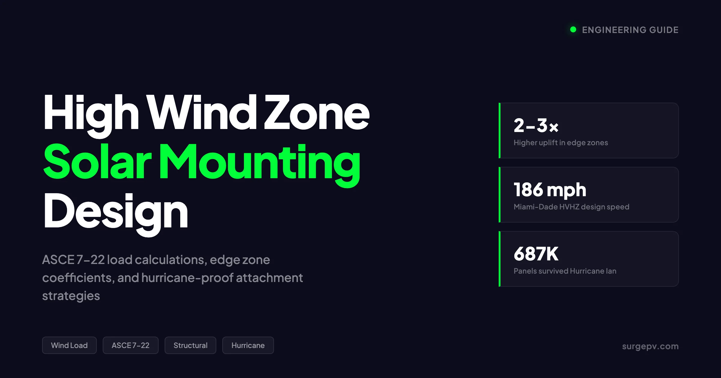
A 500 kWp rooftop project in Tampa specified 4 clamps per panel across the entire array. The engineer used interior zone coefficients for every row. When Hurricane Ian hit in 2022, the corner panels lifted first. The failure propagated inward. Seventy-three panels detached. The root cause was not the wind speed. It was the wrong coefficient for the wrong zone.
This guide covers what that engineer missed. You will learn how ASCE 7-22 divides roofs into wind load zones, why edge panels need 2-3 times more attachment strength, and how to read manufacturer engineering tables for your specific Vult and exposure category. Whether you design in Florida’s High Velocity Hurricane Zone or a Category C coastal plain, the principles are the same. Get the zone right. Get the count right. Get the hardware right.
In this guide you will learn:
- How ASCE 7-22 calculates wind pressure on rooftop solar arrays
- Why Vult, exposure category, and roof zone drive every attachment decision
- The exact difference between edge zone and interior zone uplift forces
- How to use manufacturer engineering tables from IronRidge, Unirac, and K2
- When ballasted systems fail and why penetrating mounts win in high wind
- What Miami-Dade NOA requires and how to navigate AHJ approval
- Real hurricane survival data from Ian, Irma, and Maria
- Common design mistakes that pass permit review but fail in storms
Quick Answer
High wind zone solar mounting uses ASCE 7-22 Components and Cladding methodology. Engineers calculate wind pressure from Vult (site wind speed), exposure category (B/C/D), and roof zone (interior, edge, or corner). Edge zone panels need 2-3 times more uplift resistance than interior panels. Manufacturer engineering tables give attachment counts per zone. Miami-Dade NOA certification is mandatory in Florida’s High Velocity Hurricane Zone.
See Solar Racking Design Guide for detailed guidance.
How Wind Loads Work on Rooftop Solar Arrays
Wind does not push evenly across a solar array. It creates suction. The air flowing over the roof accelerates at edges and corners. This acceleration drops pressure underneath the panels. The panels lift. This suction force, called uplift, governs solar mounting design in every wind zone.
ASCE 7-22 treats rooftop solar panels as Components and Cladding (C&C). C&C elements are building envelope parts that experience localized wind pressures higher than the main structural frame. Solar panels fit this definition because they sit above the roof surface, creating a gap where wind pressure equalizes unpredictably.
The wind pressure formula for solar panels under ASCE 7-22 is:
p = q × GCp × γE × γA
Where:
- p = design wind pressure (psf)
- q = velocity pressure at mean roof height
- GCp = external pressure coefficient from C&C tables
- γE = array edge factor (1.0 or 1.5)
- γA = pressure equalization factor (0.4 to 0.8)
Each variable multiplies the next. A mistake in any one cascades through the entire calculation. The engineer in Tampa got GCp right but missed γE for the corner rows. That single error cut the design uplift resistance in half.
Key Takeaway
Wind uplift, not downward pressure, governs solar mounting design. The pressure coefficient GCp is negative for suction. A GCp of -1.14 means the panel experiences 1.14 times the velocity pressure in upward pull. Edge and corner zones use the most negative GCp values.
Velocity Pressure: The Starting Point
Velocity pressure (q) is the kinetic energy of moving air expressed as pressure. ASCE 7-22 calculates it as:
q = 0.00256 × Kz × Kzt × Kd × Ke × V²
Where:
- Kz = velocity pressure exposure coefficient (varies with height and exposure)
- Kzt = topographic factor (1.0 for flat terrain)
- Kd = wind directionality factor (0.85 for solar panels)
- Ke = ground elevation factor (1.0 at sea level)
- V = basic wind speed (Vult in mph)
At 30 feet height, Exposure C, sea level, with Vult of 150 mph:
q = 0.00256 × 1.00 × 1.0 × 0.85 × 1.0 × (150)² = 48.96 psf
This 48.96 psf is the base pressure. The C&C coefficients multiply it. A corner zone panel with GCp = -2.0 and γE = 1.5 faces:
p = 48.96 × (-2.0) × 1.5 × 0.6 = -88.1 psf
That is 88 pounds of uplift per square foot. A standard 60-cell panel at 20.5 ft² faces 1,806 pounds of total uplift force. Four clamps rated at 500 pounds each give 2,000 pounds capacity. The safety margin is thin. Add corrosion, installation tolerance, or a slightly higher Vult, and the margin disappears.
What Is Vult?
Vult — the ultimate design wind speed — is a 3-second gust speed used for strength design. It replaced the older nominal design wind speed (Vasd) system in ASCE 7-10 and later editions. Vult values come from ASCE 7-22 wind speed maps, with separate maps for each Risk Category.
| Vult (mph) | Vasd Equivalent (mph) |
|---|---|
| 110 | 85 |
| 120 | 93 |
| 130 | 101 |
| 140 | 108 |
| 150 | 116 |
| 160 | 124 |
| 170 | 132 |
| 180 | 139 |
| 190 | 147 |
| 200 | 155 |
The 2024 International Building Code elevated solar facilities from Risk Category I to Risk Category II. This increased design wind speeds by roughly 15% for typical installations. A site that used 135 mph under Risk Category I now uses 145-150 mph under Risk Category II. Every attachment count, rail span, and standoff specification must reflect this change.
ASCE 7-22 Roof Zones: Where the Danger Lives
ASCE 7-22 divides roofs into three zones for Components and Cladding design. Each zone has a different external pressure coefficient (GCp). The zones are:
- Zone 1 — Field or interior zone: the central area of the roof, farthest from edges
- Zone 2 — Edge zone: strips along roof edges and ridges
- Zone 3 — Corner zone: the intersection of two edges, highest uplift
The width of Zone 2 and Zone 3 depends on building height and roof dimensions. For a typical low-rise building, the edge zone extends inward from the perimeter by a distance equal to 10% of the smaller building horizontal dimension or 40% of the mean roof height, whichever is smaller.
| Roof Zone | Typical GCp Range (Uplift) | Relative Uplift vs. Zone 1 |
|---|---|---|
| Zone 1 (Interior) | -0.9 to -1.1 | 1.0× (baseline) |
| Zone 2 (Edge) | -1.4 to -1.8 | 1.5-1.8× |
| Zone 3 (Corner) | -2.0 to -2.8 | 2.0-3.0× |
These coefficients come from ASCE 7-22 Figures 30.3-2 through 30.3-7. The exact value depends on roof slope, building height, and effective wind area. For solar panels, the effective wind area is typically the panel height times one-third of the panel height.
Pro Tip
Always draw the roof zone diagram before placing panels. Mark Zone 3 corners, Zone 2 edges, and Zone 1 interior. Panels that straddle zone boundaries use the more severe zone coefficient. A panel half in Zone 2 and half in Zone 3 uses Zone 3 values for its entire attachment schedule.
The Array Edge Factor (γE)
ASCE 7-22 introduces γE — the array edge factor — specifically for solar panels. It accounts for panels at the exposed perimeter of the array:
| Panel Location | γE Value |
|---|---|
| Exposed to roof edge or array edge | 1.5 |
| Unexposed (interior of array) | 1.0 |
A panel is “exposed” if it sits within 1.5 times the panel length (Lp) from the end of a row at an exposed edge. For a 6.5-foot panel, any panel within 9.75 feet of the array edge gets γE = 1.5. This factor applies on top of the roof zone coefficient. A corner zone panel with GCp = -2.0 and γE = 1.5 faces three times the uplift of an interior panel with GCp = -1.0 and γE = 1.0.
The Equalization Factor (γA)
The pressure equalization factor (γA) accounts for how much wind pressure equalizes through gaps between panels and between panels and the roof:
| Effective Wind Area | γA Value |
|---|---|
| 1-10 ft² | 0.8 |
| 10-100 ft² | Interpolated (see ASCE 7-22 Figure 29.4-8) |
| Over 100 ft² | 0.4 |
A single 60-cell panel at roughly 20.5 ft² falls in the interpolated range. A full row of panels may exceed 100 ft², qualifying for γA = 0.4. This reduction is significant — it cuts the design pressure nearly in half for large arrays. But it only applies when panels have minimum gaps of 0.25 inches between them and the gap under modules does not exceed 10 inches.
Vult by Region: Mapping Wind Speeds Across the US
ASCE 7-22 provides separate wind speed maps for each Risk Category. Solar facilities use Risk Category II (700-year mean recurrence interval). Key regional Vult values for Risk Category II include:
| Region | Vult (mph) | Exposure Category | Notes |
|---|---|---|---|
| Miami-Dade, FL | 175 | C/D | HVHZ, NOA required |
| Broward, FL | 170 | C/D | HVHZ, NOA required |
| Tampa Bay, FL | 160 | C | Hurricane-prone |
| Gulf Shores, AL | 146 | C/D | Coastal exposure |
| New Orleans, LA | 150 | C/D | Below-sea-level sites |
| Houston, TX | 145 | C | Gulf Coast |
| Corpus Christi, TX | 152 | C/D | Increased in ASCE 7-22 |
| Outer Banks, NC | 150 | D | Open water exposure |
| Norfolk, VA | 130 | C | Chesapeake Bay |
| Savannah, GA | 135 | C | Coastal plain |
| San Juan, PR | 165 | D | Hurricane-prone island |
| coastal MA | 125 | C | Nor’easter exposure |
| coastal CA | 95 | C | Lower but seismic governs |
| Phoenix, AZ | 105 | B | Desert, monsoon winds |
| Denver, CO | 115 | B | Special wind region |
| Chicago, IL | 105 | B | Lakeshore exposure C |
The ASCE 7 Hazard Tool (online) gives site-specific Vult values by address. Always verify the mapped Vult before specifying hardware. Local amendments may increase requirements. Florida’s HVHZ uses higher values than the base ASCE 7-22 maps.
Key Takeaway
ASCE 7-22 wind speed maps changed significantly from ASCE 7-16. The Florida Panhandle and Big Bend saw increases of roughly 7%. The north Atlantic coast saw decreases as contours moved offshore. Always use the current edition maps, not legacy values from old permit sets.
Exposure Categories: How Terrain Changes Everything
Exposure category modifies velocity pressure based on the terrain upwind of the building:
- Exposure B — Urban, suburban, or wooded areas with numerous closely spaced obstructions. The most common category for inland residential.
- Exposure C — Open terrain with scattered obstructions less than 30 feet high. Typical for flat rural areas and suburban edges.
- Exposure D — Flat, unobstructed areas exposed to wind flowing over open water for at least 1 mile. Applies to coastal installations and shorelines.
At 30 feet height, the Kz values are:
| Exposure | Kz at 30 ft | Relative Pressure vs. B |
|---|---|---|
| B | 0.70 | 1.0× |
| C | 0.98 | 1.4× |
| D | 1.14 | 1.63× |
A project in Exposure D faces 63% more wind pressure than the same project in Exposure B at the same Vult. This is why a Gulf Coast marina installation needs far more hardware than an identical array 10 miles inland.
Risk Categories and What Changed in 2024
The 2024 International Building Code elevated solar energy systems from Risk Category I to Risk Category II. This single change increased design wind speeds by roughly 15% for most installations.
| Risk Category | Building Type | Typical Vult Impact |
|---|---|---|
| I | Low hazard: agricultural, minor storage | No longer applies to solar |
| II | Standard: residential, commercial, most solar | Baseline (700-year MRI) |
| III | Substantial hazard: schools, assembly | 1.15× Category II |
| IV | Essential: hospitals, emergency services | 1.2× Category II |
For a solar installer, the practical impact is clear. A permit set from 2023 that used Risk Category I and 135 mph Vult is no longer code-compliant. The same site now needs 145-150 mph Vult with Risk Category II load factors. Every engineering letter, every manufacturer table, and every attachment count must reflect this.
Edge Zone vs. Interior Zone: The 2×-3× Difference
The most expensive mistake in solar wind design is treating every panel the same. Edge and corner zones experience dramatically higher uplift than interior zones. The difference is not marginal. It is structural.
Consider a typical low-slope commercial roof in Tampa with Vult = 160 mph, Exposure C, 20-foot mean roof height:
Zone 1 (Interior): q = 0.00256 × 0.90 × 1.0 × 0.85 × 1.0 × (160)² = 50.0 psf GCp = -1.0, γE = 1.0, γA = 0.6 p = 50.0 × (-1.0) × 1.0 × 0.6 = -30.0 psf
Zone 2 (Edge): q = 50.0 psf (same) GCp = -1.6, γE = 1.5, γA = 0.6 p = 50.0 × (-1.6) × 1.5 × 0.6 = -72.0 psf
Zone 3 (Corner): q = 50.0 psf (same) GCp = -2.2, γE = 1.5, γA = 0.6 p = 50.0 × (-2.2) × 1.5 × 0.6 = -99.0 psf
The corner zone panel faces 3.3 times the uplift of the interior panel. If the interior panel needs 2 clamps, the corner panel needs 7 clamps for the same safety factor. This is why generic “4 clamps per panel” rules fail. They work for the interior but leave edges critically under-designed.
What Most Guides Miss
Most online solar mounting guides give a single attachment count per panel. They do not distinguish between roof zones. A guide that says “use 4 clamps” may be correct for Zone 1 but dangerously inadequate for Zone 3. Always zone the roof first, then specify attachments per zone.
Real-World Attachment Count Example
Here is a realistic attachment schedule for a 60-cell panel (20.5 ft²) on a low-slope roof in Tampa (Vult = 160 mph, Exposure C):
| Roof Zone | Design Uplift (psf) | Total Uplift (lbs) | Clamps Needed (500 lb each) | Clamp Spacing (in) |
|---|---|---|---|---|
| Zone 1 (Interior) | 30.0 | 615 | 2 | 78 |
| Zone 2 (Edge) | 72.0 | 1,476 | 3 | 52 |
| Zone 3 (Corner) | 99.0 | 2,030 | 4 | 39 |
This table assumes 500-pound-rated clamps with a safety factor of 1.67. Actual manufacturer tables may differ based on rail profile, screw diameter, and wood species. The key point: the corner panel needs twice as many clamps as the interior panel.
Roof Slope and Height Effects
Steeper roofs and taller buildings increase wind loads:
| Factor | Impact on Uplift |
|---|---|
| Roof slope over 7° | GCp increases; panels may need sign treatment instead of C&C |
| Roof slope over 30° | Panels treated as solid signs under ASCE 7-22 Chapter 29 |
| Building height over 60 ft | Kz increases; velocity pressure rises |
| Building height over 120 ft | Additional dynamic effects; wind tunnel testing recommended |
| Panel tilt over 45° | Treated as solid signs; much higher pressure coefficients |
For low-slope commercial roofs (under 7°), the C&C methodology applies directly. For steeper residential roofs, the engineer must check whether the panel tilt relative to the roof surface pushes the design into sign territory.
Manufacturer Engineering Tables: IronRidge, Unirac, K2
Every major mounting manufacturer publishes engineering documentation with wind load tables. These tables translate ASCE 7-22 parameters into specific attachment counts, rail spans, and hardware specifications. Using these tables correctly is the difference between a permit that passes and an array that survives.
IronRidge
IronRidge provides the Design Assistant online tool and published Design Manuals for XR Rail, Standard Rail, and Light Rail systems. Key specifications:
- XR10 Rail: Light loads, residential, up to 120 mph
- XR100 Rail: Standard residential and commercial
- XR1000 Rail: Heavy commercial, high wind, long spans
IronRidge tables specify maximum rail spans based on:
- Wind speed (Vult)
- Exposure category (B/C/D)
- Roof zone (1/2/3)
- Panel dimensions and quantity per rail
- Snow load (if applicable)
For high wind zones, IronRidge typically requires:
- Reduced rail spans (often 4-5 feet vs. 6-8 feet in low wind)
- Additional mid-clamps per panel
- End clamps at every panel end in edge zones
- FlashFoot 2 or similar flashing for all roof penetrations
Unirac
Unirac’s U-Builder tool generates project-specific wind load reports. Their SolarMount Design and Engineering Guide includes:
- Pressure lookup tables (Appendix B)
- Span length tables by rail type
- Dead load analysis for ballasted systems
- Stamped engineering letters for high wind zones
Unirac’s RM SharedRail system reduces parts count but requires careful attention to shared rail spans in high wind. The RM10 and RM20 rails have different span capacities that change significantly between Exposure B and Exposure D.
K2 Systems
K2 Base is the web-based planning tool for K2 Systems. It automatically determines wind and snow loads from project location and generates:
- Full structural reports
- Assembly drawings
- Bill of materials
- Wind tunnel test references
K2’s Dome system for flat roofs includes aerodynamic wind deflectors tested to ASCE 7-22 standards. The D-Dome 6.10 ballasted system has wind tunnel test data for multiple wind speeds and exposure categories.
Pro Tip
Never mix manufacturer components in the same structural load path. IronRidge rails with Unirac clamps create unverifiable load paths. AHJs reject mixed-system installations because no single manufacturer will certify the assembly. Pick one manufacturer and use their complete system.
Reading Engineering Tables: A Practical Example
Here is how to read a typical manufacturer table for clamp spacing:
IronRidge XR100 Rail, 60-cell panel, Vult = 150 mph, Exposure C:
| Roof Zone | Max Rail Span (ft) | Clamps per Panel | End Clamp Required |
|---|---|---|---|
| Zone 1 | 6.0 | 2 | No |
| Zone 2 | 4.5 | 3 | Yes |
| Zone 3 | 3.5 | 4 | Yes |
At Vult = 170 mph (Miami-Dade), the same table shifts:
| Roof Zone | Max Rail Span (ft) | Clamps per Panel | End Clamp Required |
|---|---|---|---|
| Zone 1 | 4.5 | 3 | Yes |
| Zone 2 | 3.5 | 4 | Yes |
| Zone 3 | 2.5 | 5 | Yes |
The rail span drops by 25-30%. The clamp count increases by 50-100%. The hardware cost rises, but the array stays attached.
Stamped Engineer Letters and AHJ Approval
High wind zone projects require more than manufacturer tables. They need a licensed Professional Engineer (PE) to stamp the structural calculations. The PE verifies:
- Vult selection matches ASCE 7-22 maps
- Exposure category is correct for the site
- Roof zone dimensions are calculated per code
- Panel attachment counts satisfy load requirements
- Fastener embedment depth achieves required pull-out resistance
- Roof structure can support added dead and live loads
Florida-Specific Requirements
Florida has the most stringent solar mounting requirements in the US:
High Velocity Hurricane Zone (HVHZ):
- Applies to Miami-Dade and Broward Counties
- Requires Miami-Dade NOA or Florida Product Approval
- PE stamp from Florida-licensed engineer
- Wind speeds: 170-186 mph depending on Risk Category
- All hardware must be stainless steel Grade 316 within 5 miles of coast
Miami-Dade NOA Process:
- Manufacturer submits product for testing
- Independent lab conducts wind tunnel and pull-out tests
- Miami-Dade Building Code Compliance Office reviews
- NOA issued with specific installation parameters
- Installers must follow NOA exactly; deviations void approval
NOA approval takes 2-6 months for new products. Installers cannot use hardware without valid NOA in HVHZ. Check the Miami-Dade product control database before specifying any component.
Common Permit Rejection Reasons
| Issue | Why It Gets Rejected | How to Fix It |
|---|---|---|
| Wrong Risk Category | Using Category I instead of II | Update to 2024 IBC Category II |
| Legacy Vult | Using ASCE 7-16 maps | Reference ASCE 7-22 maps |
| Missing NOA | HVHZ without Miami-Dade approval | Specify NOA-certified hardware |
| Generic attachment count | Same count for all zones | Zone-specific attachment schedule |
| Non-stainless hardware | Coastal corrosion risk | Specify 316 stainless within 5 miles of coast |
| Insufficient lag embedment | Less than 3 inches into truss | Verify truss depth; use L-foot extensions |
| Missing PE stamp | Structural calcs not stamped | Submit stamped letter with permit |
Hurricane Code Areas: Miami-Dade NOA and Florida HVHZ
Florida’s High Velocity Hurricane Zone represents the most extreme solar mounting environment in the continental United States. Understanding HVHZ requirements is essential for any installer working in coastal Florida.
HVHZ Wind Speed Requirements
The 2023 Florida Building Code specifies these ultimate design wind speeds:
Broward County:
| Risk Category | Vult (mph) |
|---|---|
| I | 156 |
| II | 170 |
| III | 180 |
| IV | 180 |
Miami-Dade County:
| Risk Category | Vult (mph) |
|---|---|
| I | 165 |
| II | 175 |
| III | 186 |
| IV | 186 |
Solar facilities use Risk Category II (170 mph Broward, 175 mph Miami-Dade). Essential facilities like hospitals use Category IV (186 mph). The difference between 170 and 186 mph is not trivial. At 186 mph, velocity pressure is 19% higher than at 170 mph. Every attachment, every rail, and every standoff must account for this.
NOA-Certified Products for HVHZ
The following mounting systems carry Miami-Dade NOA for high wind applications:
| Manufacturer | Product | NOA Wind Rating | Application |
|---|---|---|---|
| IronRidge | XR Rail series | 170+ mph | Sloped roof, penetrating |
| Unirac | SolarMount | 170+ mph | Sloped roof, penetrating |
| K2 Systems | CrossRail | 170+ mph | Sloped roof, penetrating |
| S-5! | ColorGard / VersaGard | 180+ mph | Standing seam metal |
| Solar Stack | Adhesive mount | 180+ mph | Tile and shingle |
| Quick Mount PV | QBase | 170+ mph | Sloped roof, flashing |
Each NOA specifies exact installation parameters: fastener type, embedment depth, spacing, torque values, and compatible roof types. Deviating from the NOA — even slightly — invalidates the approval and voids the structural warranty.
Real-World Example
A contractor in Fort Lauderdale substituted Grade 304 stainless lag bolts for the Grade 316 bolts specified in the NOA. The inspector flagged it. The contractor argued 304 was “close enough.” The AHJ rejected the permit. The contractor re-ordered 316 bolts, delayed the project by 3 weeks, and paid rush shipping. The $200 bolt savings cost $4,000 in delays.
Ballasted vs. Penetrating Mounts in High Wind
The choice between ballasted and penetrating mounts is one of the most consequential decisions in high wind zone design. The wrong choice can overload the roof structure or leave the array vulnerable to uplift.
Ballasted Systems: When They Work and When They Fail
Ballasted systems use concrete blocks or pavers to hold panels down. No roof penetrations. No leaks. Fast installation. These advantages make ballasted systems popular for flat commercial roofs.
But ballasted systems have a critical weakness in high wind: ballast weight increases with the square of wind speed. At low wind speeds, a 40-pound block may suffice. At 150 mph, the same panel may need 200+ pounds of ballast.
| Vult (mph) | Typical Ballast per Panel (lbs) | Roof Load (psf) |
|---|---|---|
| 100 | 40-60 | 4-6 |
| 120 | 80-120 | 8-12 |
| 140 | 150-220 | 15-22 |
| 160 | 250-400 | 25-40 |
| 180 | 400+ | 40+ |
At 180 mph, ballasted systems add 40+ psf to the roof. Most commercial roofs are rated for 20-30 psf live load. The ballast alone can exceed structural capacity. This is why Florida HVHZ prohibits ballasted systems for most applications.
Modern aerodynamic ballasted systems (like K2 Dome with wind deflectors) reduce ballast requirements by 30-50%. But even these have practical limits around 140-150 mph Vult.
Penetrating Systems: The High Wind Standard
Penetrating systems anchor directly to roof structural members. Lag bolts or screws embed into rafters or trusses. This creates a positive mechanical connection that resists uplift through embedment strength, not weight.
| Factor | Ballasted | Penetrating |
|---|---|---|
| Wind resistance | Limited by roof capacity | Limited by fastener strength |
| Dead load added | 5-40+ psf | 2-3 psf |
| Roof structural requirement | Must support heavy continuous load | Minimal structural burden |
| Installation speed | 30% faster | Slower (drilling, sealing) |
| Waterproofing risk | None | Requires proper flashing |
| High wind suitability | Marginal above 140 mph | Rated to 180+ mph |
| Code acceptance | Restricted in HVHZ | Required in most high wind zones |
| Removability | Easy | Permanent modifications |
For high wind zones, penetrating mounts are the clear choice. The only exceptions are:
- Roofs with active waterproofing warranties that prohibit penetrations
- Historic buildings where structural modification is restricted
- Very low wind zones (under 110 mph) where ballast is structurally feasible
Hybrid Designs: The Compromise Approach
Some designers use a hybrid approach:
- Ballasted blocks for interior Zone 1 panels (lower uplift)
- Mechanical anchors for Zone 2 and Zone 3 panels (higher uplift)
This reduces total roof load while maintaining edge zone security. But hybrid designs require careful engineering. The ballasted panels cannot rely on anchored panels for wind shielding unless the spacing meets ASCE 7-22 shielding criteria. Most hybrid designs need a PE stamp and detailed load path analysis.
Tradeoff
Ballasted systems win on installation speed and waterproofing simplicity. Penetrating systems win on wind resistance and structural efficiency. In wind zones above 140 mph, penetrating mounts are not just better — they are often the only code-compliant option. The installer who defaults to ballast in high wind zones is making a structural bet that rarely pays off.
Hurricane Survival Data: What Actually Happened
Real hurricane data reveals what works and what fails. The gap between code-compliant design and storm survival is wider than most installers assume.
Hurricane Ian (2022): Category 5, 150+ mph
Hurricane Ian made landfall near Fort Myers, Florida, with sustained winds of 150 mph and gusts over 160 mph. The storm tested thousands of solar installations. Also see: Us Residential Solar Market Trends 2026.
Babcock Ranch, Florida:
- 687,000 solar panels across 440 acres
- Sustained 150 mph winds with minimal damage
- Only 2 panels replaced due to debris impact
- The same array survived Hurricane Irma (2017) with similar results
- Residents maintained power while surrounding areas lost grid for weeks
Tesla Solar Roof / Powerwall:
- Withstood 155 mph winds and 10-foot storm surge
- Powerwall submerged for hours, continued operating
- Roof integrity maintained throughout storm
Overall Damage Rate:
- Less than 1% total system failure rate across 50,000+ homes with solar
- Primary damage cause: flying debris, not wind forces
- NREL data: average annual damage rate under 0.1% for 50,000 systems (2009-2013)
Hurricane Irma (2017): Category 5, 185 mph Peak
Babcock Ranch:
- 343,000 panels at the time (Phase 1)
- Zero panels dislodged
- Only 2 panels replaced (debris damage)
Barbuda Solar Plant:
- 1 MW ground-mount system
- Complete destruction — panels blown and washed away
- Failure attributed to inadequate foundation design for combined wind and surge For more on this topic, see Design Commercial Solar System 1MW.
Florida Rooftop Solar (General):
- Mixed results
- Older systems (pre-2010) showed higher failure rates
- Newer systems with modern mounting performed well
Hurricane Maria (2017): 150-175 mph Winds
San Juan VA Hospital:
- 645 kW rooftop array
- 100% operational throughout the storm
- Maintained power while 95% of Puerto Rico lost electricity
Puerto Rico Solar Farms:
- One-third of farms reported over 50% panel damage
- Same project, Phase 1 vs. Phase 2:
- Phase 1: 25% damage
- Phase 2: 75% damage
- Same panels. Different tilt angles, elevation heights, and cantilever designs.
The UC Berkeley Study: Code vs. Reality
A 2023 UC Berkeley study found troubling gaps between code ratings and actual performance:
- Solar panels in the Caribbean and Florida “failed at lower winds than they were supposed to”
- Systems were “performing below code requirements”
- Common failure modes:
- Clamp failures (insufficient torque or wrong clamp for rail)
- Racking fractures or buckling (under-sized rails for actual loads)
- Bolt shear failure (wrong bolt grade for wind load)
- Bolt loosening (inadequate thread-locking in vibration)
The study concluded that installation quality and edge zone design matter as much as the hardware rating. A system rated for 180 mph can fail at 120 mph if edge panels use interior zone attachment counts.
Key Takeaway
Properly engineered solar arrays survive Category 5 hurricanes. Babcock Ranch proved it twice. But the keyword is “properly engineered.” The UC Berkeley study shows that code-compliant designs still fail when edge zones are under-designed, clamps are under-torqued, or hardware corrodes. Engineering on paper is not the same as engineering in the field.
Common Code Mistakes That Pass Review but Fail in Storms
Permit approval does not guarantee storm survival. These mistakes slip through plan review regularly:
Mistake 1: Using Interior Coefficients for Edge Zones
This is the most common and most dangerous error. The designer calculates one attachment count for the entire array using Zone 1 coefficients. Edge and corner panels get the same hardware as interior panels. In a storm, edges lift first. Once edge panels detach, the interior loses shielding. The failure propagates inward.
Fix: Calculate attachment counts separately for each roof zone. Mark Zone 2 and Zone 3 on the panel layout. Specify different clamp counts, rail spans, or standoff spacing for each zone.
Mistake 2: Ignoring the 2024 IBC Risk Category Change
Permit sets copied from 2023 projects still use Risk Category I. The 2024 IBC requires Category II for all solar facilities. This increases Vult by roughly 15% for most sites. Old attachment counts are no longer sufficient.
Fix: Verify the Risk Category on every project. Use ASCE 7-22 Risk Category II maps. Update manufacturer table references to current editions.
Mistake 3: Wrong Exposure Category
A coastal project classified as Exposure B because the building sits behind a single row of dunes. The correct category is D because wind flows over open water for more than 1 mile upwind. The velocity pressure is 63% higher than the B assumption.
Fix: Walk the site. Look upwind. If open water, flat marsh, or unobstructed plain extends 1 mile or more, use Exposure D. When in doubt, use the more severe category.
Mistake 4: Non-Stainless Hardware Near Coastlines
Grade 304 stainless corrodes in salt air. Grade 316 is required within 5 miles of coast in Florida and recommended within 500 meters of any saltwater. Corroded bolts lose 30-50% of their strength within 5 years.
Fix: Specify 316 stainless for all hardware within 5 miles of coast. Inspect annually for corrosion. Replace any hardware showing rust.
Mistake 5: Insufficient Lag Bolt Embedment
Lag bolts must embed at least 3 inches into solid wood structural members. Screws into plywood sheathing or 1.5-inch truss plates pull out under uplift. The fastener is only as strong as what it screws into.
Fix: Verify rafter or truss depth before specifying fasteners. Use L-foot extensions or standoffs to achieve proper embedment. Never rely on sheathing alone.
Mistake 6: Missing End Clamps
End clamps prevent panels from sliding longitudinally along rails. In high wind, panels without end clamps can slide off the rail ends. This is especially critical in edge zones where γE = 1.5 applies.
Fix: Specify end clamps at every panel end in Zone 2 and Zone 3. Some manufacturer tables require end clamps in all zones above certain wind speeds.
What Most Guides Miss
Most solar mounting guides focus on rail selection and clamp placement. They rarely discuss the structural load path from panel to clamp to rail to L-foot to fastener to rafter. A chain is only as strong as its weakest link. In high wind zones, the weakest link is often the fastener embedment or the wood fiber tear-out around the lag bolt. Check every link in the chain.
Cost Impact of Wind Zone Upgrades
High wind compliance adds cost. But the cost of compliance is small compared to the cost of failure.
Material Cost Increases
| Wind Zone | Typical Attachment Count | Hardware Cost per kW | vs. Low Wind |
|---|---|---|---|
| Low wind (under 110 mph) | 2 clamps per panel | $25-35 | Baseline |
| Moderate (110-130 mph) | 2-3 clamps per panel | $35-50 | +40% |
| High (130-150 mph) | 3-4 clamps per panel | $50-70 | +100% |
| Hurricane (150-170 mph) | 4-5 clamps per panel | $70-100 | +200% |
| Extreme HVHZ (170+ mph) | 5+ clamps per panel | $100-150 | +300% |
These costs include clamps, rails, L-feet, flashing, and fasteners. Labor increases proportionally. More clamps mean more drilling, more sealing, more inspection.
Engineering and Permitting Costs
| Item | Low Wind Zone | High Wind Zone | HVHZ |
|---|---|---|---|
| PE stamp | $500-1,000 | $1,000-2,500 | $2,500-5,000 |
| Manufacturer engineering letter | Often included | $200-500 | $500-1,000 |
| NOA verification | N/A | N/A | Required (no cost) |
| Permit fees | $200-500 | $300-800 | $500-1,500 |
| Inspection rounds | 1-2 | 2-3 | 3-5 |
The 2024 IBC Impact
The Risk Category II elevation added roughly 15% to wind load factors. For a typical commercial project, this translated to:
- 1-5% increase in total project cost
- 10-20% increase in mounting hardware cost
- 5-15% increase in labor for additional attachments
These increases are modest because mounting hardware is a small fraction of total project cost. Modules and inverters dominate the budget. A 15% hardware increase adds only 1-5% to the total.
Cost of Failure
Total array replacement after a hurricane:
- Residential (10 kW): $25,000-35,000
- Commercial (500 kW): $800,000-1,200,000
- Utility (10 MW): $12,000,000-18,000,000
Insurance may cover some losses. But deductibles, business interruption, and reputation damage add up. The upfront premium for proper high wind design pays for itself many times over if it prevents even one failure.
SurgePV Analysis
At $0.10-0.25 per watt, high wind zone upgrades add roughly 1-3% to total project cost. For a 500 kW commercial project, that is $50,000-125,000. The same project losing 20% of panels to a storm faces $160,000-240,000 in replacement costs plus months of lost production. High wind design is not an expense. It is insurance with a positive expected value.
For a direct comparison, see Arka 360 vs SurgePV.
International Standards: Eurocode and Beyond
ASCE 7-22 governs US design. International projects use different standards with similar principles.
Eurocode 1 (EN 1991-1-4)
Eurocode 1 uses a different formula but similar zone concepts:
w = qp × cp,net × cs × cd
Where:
- qp = peak velocity pressure
- cp,net = net pressure coefficient
- cs = size factor
- cd = dynamic factor
EN 1991-1-4 divides flat roofs into zones F, G, H, and I:
| Zone | Description | cpe,10 (Uplift) |
|---|---|---|
| F (Corner) | Most severe | -2.5 to -2.0 |
| G (Edge) | High suction | -2.0 |
| H (Transition) | Moderate | -1.2 |
| I (Center) | Lowest | -0.6 to -0.9 |
Research by Geurts, van Bentum, and Blackmore developed specific net pressure coefficients for solar panels on flat roofs:
| Situation | cp,net (Upward) | cp,net (Downward) |
|---|---|---|
| High end toward wind (corner/edge) | -3.5 to -3.8 | +0.6 to +0.9 |
| Low end toward wind (corner/edge) | -3.1 to -3.3 | +0.6 to +0.9 |
| Side toward wind (edge) | -3.1 to -3.4 | +0.7 to +0.9 |
| Sheltered by upwind rows | -0.7 to -0.8 | +0.6 to +0.7 |
These coefficients are more severe than ASCE 7-22 for comparable conditions. European designers often use wind tunnel testing or national guidelines (like NVN 7250 in the Netherlands) for specific solar panel applications. Also see: European Solar Incentives. Read more about School Solar Installation Case Study. For Europe-specific compliance details, see Europe solar compliance.
German Wind Zones (DIN EN 1991-1-4/NA)
Germany divides the country into four wind zones: Also see: Germany solar subsidies. For Germany-specific information, see Community Solar Projects Germany.
| Wind Zone | Basic Wind Speed (m/s) | Application |
|---|---|---|
| WZ 1 | 22.5 | Inland, sheltered |
| WZ 2 | 25.0 | Most of Germany |
| WZ 3 | 27.5 | Coastal plains |
| WZ 4 | 30.0 | North Sea coast, islands |
Solar installations in WZ 4 need enhanced mounting. The North Sea coast and islands experience sustained high winds plus salt corrosion. Stainless steel hardware is mandatory.
Australian and New Zealand Standards (AS/NZS 1170.2)
Australia uses wind regions A through D:
| Region | Wind Speed | Description |
|---|---|---|
| A | 45 m/s (101 mph) | Standard |
| B | 57 m/s (128 mph) | Intermediate |
| C | 66 m/s (148 mph) | Cyclonic |
| D | 80 m/s (179 mph) | Severe cyclonic |
Regions C and D require cyclone-rated mounting systems with engineering certification. The Australian standard emphasizes debris impact resistance in addition to wind uplift. For the latest details on Australia, see Solar Energy in Australia. For Australia-specific compliance details, see Australia comparisons/lgc-vs-stc.
Designing for High Wind: A Step-by-Step Process
Here is the practical workflow for high wind zone solar mounting design:
Step 1 — Determine Vult: Use the ASCE 7 Hazard Tool or ASCE 7-22 maps. Input the project address. Record Vult for Risk Category II. Check local amendments (Florida HVHZ uses higher values).
Step 2 — Determine Exposure Category: Walk the site. Look upwind. Classify as B, C, or D based on terrain. When in doubt, use the more severe category.
Step 3 — Determine Roof Zones: Measure building dimensions and height. Calculate zone widths per ASCE 7-22. Draw Zone 1, Zone 2, and Zone 3 on the roof plan.
Step 4 — Place Panels and Identify Zone for Each: Lay out the array. Mark each panel’s zone. Panels straddling boundaries use the more severe zone.
Step 5 — Select Manufacturer and Access Engineering Tables: Choose IronRidge, Unirac, K2, or another manufacturer with NOA (if required). Access their online tool or published tables.
Step 6 — Calculate Attachment Counts per Zone: Input Vult, exposure, zone, panel size, and roof slope. Record clamp counts, rail spans, and end clamp requirements for each zone.
Step 7 — Verify Fastener Embedment: Check rafter/truss spacing and depth. Specify fasteners with adequate embedment. Use standoffs or L-foot extensions if needed.
Step 8 — Specify Materials: Use 316 stainless within 5 miles of coast. Verify all hardware matches manufacturer NOA specifications.
Step 9 — Prepare PE-Stamped Calculations: Compile load calculations, manufacturer tables, and fastening details. Submit to licensed PE for review and stamp.
Step 10 — Submit for Permit: Include stamped calcs, manufacturer cut sheets, NOA documentation (if required), and zone-marked panel layout.
Pro Tip
Build a spreadsheet template with Vult, exposure, and zone as inputs. Link to manufacturer table lookups. The template should auto-calculate attachment counts for each zone. This saves hours on every project and eliminates zone-calculation errors.
When to Use [Solar Design Software] for Wind Load Verification
Manual calculations work for simple roofs. Complex projects need software verification. Solar design software like SurgePV automates wind load checks as part of the structural design workflow.
Key features to look for:
- Automatic Vult lookup by project address
- Exposure category selection
- Roof zone visualization on panel layout
- Manufacturer table integration
- Attachment count auto-calculation
- PE-ready export of structural calculations
Software does not replace engineering judgment. But it eliminates arithmetic errors, ensures consistent zone application, and speeds up permit preparation. For high-volume installers in hurricane zones, software-based verification is essential.
Design for Any Wind Zone with SurgePV
Model your roof, specify your wind zone, and get code-compliant attachment counts automatically.
Book a DemoNo commitment required · 20 minutes · Live project walkthrough
Narrative: The Puerto Rico Array That Survived Maria
Dr. Carlos Ortiz oversaw a 645 kW rooftop installation at the San Juan VA Hospital in 2016. The project used penetrating mounts with 316 stainless fasteners. The engineer specified 4 clamps per panel in edge zones and 3 clamps in the interior. Every fastener embedded 3.5 inches into concrete-filled steel joists.
When Hurricane Maria struck in September 2017, sustained winds reached 175 mph at the hospital. Ninety-five percent of Puerto Rico lost power. The VA Hospital’s solar array kept operating. Not one panel detached. The array powered critical medical equipment through the storm and the weeks-long grid outage that followed.
Three miles away, a similar-sized array on a commercial building used ballasted mounts with interior-zone attachment counts across the entire roof. The engineer had copied the design from a low-wind project in Orlando. After the storm, 40% of the panels were gone. The ballast blocks scattered across the parking lot.
The difference was not luck. It was engineering. The VA Hospital project treated every panel according to its roof zone. The commercial project treated every panel the same. In 175 mph winds, that difference separated survival from total loss.
Tools & Further Reading
Continue exploring related SurgePV resources:
Frequently Asked Questions
What is the difference between edge zone and interior zone wind uplift on solar panels?
Edge zones experience 2-3 times higher wind uplift than interior zones. ASCE 7-22 applies an edge factor (γE) of 1.5 to exposed panels near roof edges, while interior panels use γE = 1.0. This means a panel 3 feet from a roof edge may need 50% more attachments than an identical panel in the array center.
What wind speed can solar panels withstand?
Properly engineered solar panels can withstand 150-186 mph winds depending on the design standard. Babcock Ranch’s 687,000-panel array survived Hurricane Ian’s 150 mph winds with minimal damage. Miami-Dade NOA-approved systems are tested to 186 mph for Risk Category IV structures.
How many attachments does a solar panel need in a high wind zone?
Standard residential panels use 2-4 attachments. High wind zones require 4+ standoffs or clamps per panel. Edge and corner zones need 30-50% closer spacing than interior zones. Exact counts come from manufacturer engineering tables matched to local Vult, exposure category, and roof zone.
What is Vult in solar mounting design?
Vult is the ultimate design wind speed — a 3-second gust speed used for strength design. ASCE 7-22 maps show Vult by location and risk category. For example, Miami-Dade Risk Category II uses 175 mph Vult. Engineers convert Vult to velocity pressure, then apply pressure coefficients to find uplift forces on each panel.
Do ballasted or penetrating mounts work better in high wind zones?
Penetrating mounts outperform ballasted systems in high wind zones. Ballasted systems need exponentially more weight as wind speed rises, often exceeding roof capacity. Penetrating mounts anchor directly to structural members. Florida HVHZ mandates penetrating mounts for most applications. Hybrid designs use ballast in the interior and mechanical anchors at edges.
What is Miami-Dade NOA and why does it matter for solar mounting?
NOA stands for Notice of Acceptance — a product approval from Miami-Dade County for use in High Velocity Hurricane Zones. NOA certification requires wind tunnel testing, pull-out testing, and corrosion resistance verification. Installers in Broward and Miami-Dade counties cannot use mounting hardware without valid NOA documentation.
How much does high wind zone compliance add to solar project costs?
The 2024 IBC elevation of solar facilities to Risk Category II added roughly 15% to wind load factors, increasing material costs by 1-5% overall. Hurricane-zone projects add $0.10-0.25 per watt for enhanced hardware, engineering stamps, and NOA-certified components. The cost of failure — total array loss — far exceeds the upfront premium.
What exposure category should I use for coastal solar installations?
Coastal installations over open water for at least 1 mile use Exposure Category D — the most severe. Flat, unobstructed terrain uses Category C. Suburban or wooded areas use Category B. Exposure D increases velocity pressure by roughly 30% compared to Category B at the same wind speed, directly increasing attachment requirements.
Can solar panels survive a Category 5 hurricane?
Yes, when properly engineered. Babcock Ranch’s solar field survived both Hurricane Irma (185 mph peak) and Hurricane Ian (150 mph) with only 2 panels replaced out of 687,000. However, a 2023 UC Berkeley study found some residential rooftop systems in the Caribbean failed below their rated wind speeds due to clamp failures, bolt shear, and inadequate edge zone design.
What is the most common mistake in high wind zone solar design?
The most common mistake is using interior zone pressure coefficients for edge and corner panels. This single error can leave edge panels with half the attachment strength they need. Other frequent errors include: ignoring the 2024 IBC Risk Category II elevation, using non-stainless hardware within 500 meters of coastlines, and failing to verify rafter spacing before specifying lag bolt embedment depth. Solar proposal software generates professional quotes in minutes.