Quick Answer
Solar project management follows five phases: development (permits, interconnection), procurement (equipment ordering), construction (installation, commissioning), closeout (documentation, training), and O&M handover. A residential project takes 30–90 days; commercial takes 3–12 months. Critical path items: permitting and utility interconnection.
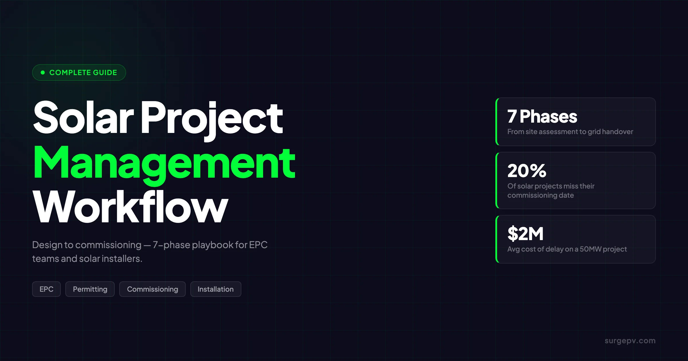
Most solar projects don’t fail because of bad panels or poor weather. They fail because of gaps between phases — a design error that surfaces during permit review, an equipment order that misses the installation window by two weeks, a commissioning test that reveals a wiring mistake nobody flagged during installation. The average 50MW solar project that hits a delay costs approximately $2M in overruns, according to construction monitoring data from Percepto. Roughly 20% of all planned solar capacity misses its intended commissioning date. This guide maps the full project management workflow — from first site visit to grid handover — with phase-specific checklists, timeline benchmarks, and the decision points that most project managers get wrong.
Solar project management follows five phases: development (permits, interconnection), procurement (equipment ordering), construction (installation, commissioning), closeout (documentation, training), and O&M handover. A residential project takes 30–90 days; commercial takes 3–12 months. Critical path items: permitting and utility interconnection.
Solar project management follows five phases: development (permits, interconnection), procurement (equipment ordering), construction (installation, commissioning), closeout (documentation, training), and O&M handover. A residential project takes 30–90 days; commercial takes 3–12 months. Critical path items: permitting and utility interconnection.
TL;DR — Solar Project Management
Solar project management spans seven phases: site assessment, design, permitting, procurement, installation, commissioning, and handover. Residential projects take 6–18 weeks. Commercial rooftop runs 3–6 months. Utility-scale runs 12–24 months. Design accuracy at Phase 2 is the highest-leverage factor for compressing the overall timeline — every permit rejection adds 2–4 weeks, and most rejections trace back to incomplete or non-code-compliant engineering drawings.
What this guide covers:
- The 7-phase solar project lifecycle with specific deliverables at each gate
- Phase-by-phase timeline benchmarks for residential, commercial, and utility-scale
- The commissioning tests that matter and how to interpret results
- Risk management frameworks for schedule, technical, financial, and regulatory exposures
- How integrated solar design software compresses timelines across every phase
What Is Solar Project Management?
Solar project management is the discipline of planning, coordinating, and controlling all activities required to deliver a solar energy system — from the first site visit through the day the system reaches its commercial operation date and hands over to an operations team.
It combines construction project management with electrical engineering, financial oversight, and regulatory compliance. A residential installer managing a 10 kW rooftop system and a utility-scale EPC managing a 100 MW ground mount are both doing solar project management — just at different scales and with different levels of formality. See Ground Mounted Solar Design Guide for detailed guidance.
The core challenge is that solar projects involve multiple sequential phases where each phase’s output directly gates the next. A poorly scoped site assessment produces an under-engineered design. A design that doesn’t meet the AHJ’s code requirements produces a permit rejection. A permit rejection delays the procurement order. A delayed order pushes the installation crew to another project. By the time the schedule recovers, the commissioning window has shifted and the interconnection agreement may be at risk.
This is why project management in solar isn’t a soft coordination skill — it’s a technical discipline that determines whether a project delivers on time and on budget.
EPC vs. Self-Perform
Most solar projects above 50 kW are delivered under an EPC (Engineering, Procurement, Construction) model: a single contractor holds responsibility for all three functions under one contract. The EPC model reduces coordination friction between engineering and procurement, provides a single point of accountability for the client, and typically compresses timelines because the same team manages the design-to-equipment-to-installation handoff.
The alternative is self-perform: the owner contracts separately for engineering, equipment supply, and construction labor. Self-perform can reduce total cost on large utility-scale projects where owners have in-house project management capability. The risk is that handoffs between separate contractors create gaps — an engineering firm that delivers drawings two weeks late pushes every downstream contractor’s schedule.
For commercial projects under 500 kW, the EPC model almost always makes more sense. The coordination overhead of managing three separate contracts erodes the potential cost savings.
Key Project Roles
| Role | Responsibility |
|---|---|
| Project Manager | Overall schedule, budget, stakeholder communication |
| Project Engineer | Technical design oversight, permit coordination |
| Site Supervisor | Day-to-day construction management, safety compliance |
| Procurement Lead | Equipment sourcing, supplier management, delivery tracking |
| Commissioning Engineer | Testing protocols, grid coordination, punch list |
The 7-Phase Solar Project Lifecycle
Every solar project follows the same seven phases, regardless of scale. The duration and complexity of each phase scales with project size, but the sequence and deliverables are consistent.
| Phase | Residential (< 10 kW) | Commercial (10–500 kW) | Utility-Scale (1+ MW) |
|---|---|---|---|
| 1. Site Assessment | 1–3 days | 1–2 weeks | 2–8 weeks |
| 2. Design & Engineering | 3–7 days | 2–4 weeks | 4–12 weeks |
| 3. Permitting & Interconnection | 2–8 weeks | 4–12 weeks | 3–12 months |
| 4. Procurement | 1–3 weeks | 4–8 weeks | 3–6 months |
| 5. Installation | 1–3 days | 2–6 weeks | 2–12 months |
| 6. Commissioning | 1 day | 3–7 days | 2–6 weeks |
| 7. Handover & O&M Setup | 1–2 days | 1–2 weeks | 2–4 weeks |
| Total (NTP to COD) | 6–18 weeks | 3–6 months | 12–24 months |
The phases often overlap in practice. Procurement can begin after design is 80% complete. Site preparation can start while permits are under review. Experienced project managers know which overlaps are safe and which create rework risk.
Phase 1: Site Assessment and Feasibility
Site assessment produces the data that every downstream phase depends on. Errors or omissions here compound through the entire project. A missed structural deficiency discovered during installation means a redesign, a permit revision, and a delayed commissioning date.
What Happens in Phase 1
The site assessment team gathers:
- Solar resource data: irradiance measurements (GHI, DNI, DHI), tilt and azimuth potential, historical weather patterns
- Shading analysis: horizon profiles, near-shade obstructions (trees, HVAC units, adjacent buildings), seasonal shading patterns
- Structural assessment: roof load capacity for rooftop systems, foundation soil conditions for ground mounts, wind and snow load requirements
- Electrical assessment: existing utility connection point, available capacity, meter configuration, transformer proximity
- Regulatory screening: AHJ identification, utility tariff classification, applicable incentive programs
For residential projects, much of this can be done remotely using satellite imagery and aerial LiDAR data. For commercial and utility-scale projects, at least one physical site visit is required to verify structural conditions and identify site-specific constraints.
Pro Tip
Run a solar shadow analysis before finalizing any layout. Shading is the most common source of design revisions during permitting — an AHJ reviewer will flag a panel layout where shadows from a rooftop HVAC unit will reduce the east-wing array output by 30%, even if the installer missed it.
Phase 1 Deliverables
- Site survey report with photos, measurements, and structural notes
- Shading analysis report with annual energy loss quantification
- Feasibility estimate with system size range and preliminary financial projections
- Go/no-go decision with identified constraints
Common Phase 1 Mistakes
Relying on satellite data without a physical inspection: Satellite imagery resolves roof type and pitch but misses structural damage, non-standard construction, or utility service panel conditions. For any project above 10 kW, a site visit is worth the cost.
Skipping the shading analysis: A string layout designed without shading data may look correct on paper but lose 15–25% of annual production to shading that could have been avoided with optimized string groupings or alternative mounting strategies.
Underestimating interconnection complexity: For commercial projects near grid capacity limits, the utility interconnection study can add 3–6 months to the overall schedule. Identifying this early lets you start the application process before design is finalized.
Phase 2: System Design and Engineering
System design translates the site data from Phase 1 into the technical documents that drive every downstream phase — the permit package, the equipment procurement list, and the installation drawings. Design quality directly determines permitting speed and change order frequency.
What Happens in Phase 2
The engineering team produces:
- Electrical single-line diagram (SLD): shows the complete electrical architecture from panels through inverters, disconnect switches, meter, and utility connection point
- String layout and wiring plan: assigns panels to strings, calculates string lengths, specifies wire gauge and conduit routing
- Structural drawings: shows racking layout, attachment points, load calculations
- Equipment specifications: panel model and quantity, inverter model and capacity, racking system, BOS components
- Energy production model: annual kWh output by month, performance ratio, degradation schedule
The design must comply with the National Electrical Code (NEC Article 690 for PV systems), local AHJ requirements, and the utility’s interconnection standards. An experienced project engineer knows that AHJ requirements vary significantly between jurisdictions — what passes in one county may require additional drawings or calculations in the next.
This is where solar design software has the highest leverage in the entire project lifecycle. Accurate, code-compliant design drawings pass permit review on first submission. Every revision cycle adds 2–4 weeks to the schedule and often requires rescheduling the procurement order.
The Link Between Design and Permitting Speed
SEIA’s 2025 Solar Market Insight Report found that permit processing times vary by 300–400% between jurisdictions, but within any jurisdiction, projects with complete and accurate permit packages move through review 40–60% faster than projects with incomplete submissions.
The leading causes of permit rejection:
- Missing or incorrect wire sizing calculations
- String configuration that exceeds inverter input limits
- Structural attachment details that don’t match the AHJ’s required format
- Inconsistencies between the SLD and the panel layout drawing
- Missing equipment spec sheets or UL listing documentation See Solar Cable Sizing Calculation for detailed guidance.
All five are preventable with thorough design software that performs automatic code checks before the permit package is generated.
Key Takeaway
Design accuracy is the highest-leverage factor in compressing the overall project timeline. A permit rejection adds 2–4 weeks per revision cycle. Projects with clean first-submission permit packages typically reach NTP 3–5 weeks earlier than those with revision cycles.
Phase 2 Deliverables
- Electrical single-line diagram
- Panel layout drawing with string groupings
- Structural attachment drawings and load calculations
- Equipment schedule (bill of materials)
- Energy production model with monthly output projections
- Permit-ready drawing package (formatted for the AHJ)
Design for Commissioning
One often-overlooked design output is the commissioning plan. The design engineer knows the expected IV curve parameters for each string, the expected open-circuit voltages, and the design production targets. Commissioning engineers need this data to distinguish a test result that indicates a real fault from one that reflects normal module variation.
Building the commissioning benchmarks into the design package — not as an afterthought after installation — saves significant time during Phase 6.
Phase 3: Permitting and Interconnection
Permitting is the phase most outside a project manager’s direct control. AHJ review times, utility interconnection queues, and the availability of inspectors are all external constraints. The best a project manager can do is submit a clean, complete package and respond to any information requests within 24 hours.
Permit Submissions
Most solar projects require at least three separate permit submissions:
- Building permit (structural): submitted to the local AHJ, covers the structural attachment of the racking system and rooftop penetrations
- Electrical permit: covers the DC and AC electrical work, often submitted simultaneously with the building permit
- Utility interconnection application: submitted to the local distribution utility, covers the grid-tie point, metering, and anti-islanding requirements
For commercial projects, additional submissions may include fire department access drawings (for rooftop systems meeting NFPA 70 setback requirements), stormwater management plans (for ground-mount systems), and environmental impact assessments.
The typical permit processing timeline:
| Jurisdiction Type | Building Permit | Electrical Permit | Interconnection App |
|---|---|---|---|
| Streamlined (SolarAPP+) | 1–5 days | 1–5 days | 2–4 weeks |
| Standard municipal | 2–6 weeks | 2–6 weeks | 4–8 weeks |
| Complex / multi-step review | 6–14 weeks | 6–14 weeks | 3–6 months |
The permitting-to-PTO process for residential systems in markets using SolarAPP+ (the DOE’s automated permit review tool) can cut residential permit time from weeks to days. Commercial projects don’t yet have an equivalent, though some utilities have streamlined interconnection queues for systems under 100 kW.
For a detailed breakdown of the NTP-to-COD milestones and what triggers each, see the guide on NTP, PTO, and COD in solar projects.
Managing the Interconnection Queue
For commercial and utility-scale projects, the utility interconnection application is often the longest single phase. The interconnection queue at many utilities runs 6–18 months for projects requiring a full impact study (typically above 500 kW). Projects below the utility’s simplified interconnection threshold (usually 10 kW for residential, 100–500 kW for commercial depending on the utility) move faster.
Tactics that reduce interconnection timeline:
- Submit the interconnection application as early as possible — it can run in parallel with design and permitting
- Confirm the utility’s interconnection threshold before finalizing system size (sizing slightly below the threshold can save months)
- Request a pre-application meeting with the utility’s interconnection team for projects above 100 kW — this surfaces potential issues before the formal application
Phase 3 Deliverables
- All permits approved (building, electrical, utility interconnection)
- Notice to Proceed (NTP) issued
- Interconnection agreement signed
- Inspection schedule confirmed with AHJ
- Commissioning date estimated based on permit approval date
Phase 4: Procurement and Equipment Sourcing
Procurement begins as soon as design is sufficiently finalized — typically at 80–90% design completion, not after permits are approved. Waiting for permit approval before placing equipment orders adds 4–12 weeks of unnecessary lead time on commercial projects.
Equipment Categories and Lead Times
| Equipment Category | Typical Lead Time (2026) |
|---|---|
| Solar modules (standard) | 4–8 weeks |
| Solar modules (high-efficiency / bifacial) | 6–12 weeks |
| String inverters (< 100 kW) | 3–6 weeks |
| Central inverters (> 100 kW) | 8–16 weeks |
| Racking systems (rooftop) | 2–4 weeks |
| Racking systems (ground mount) | 6–12 weeks |
| Monitoring systems | 2–4 weeks |
| Electrical BOS (conduit, wire, breakers) | 1–2 weeks |
Lead times for central inverters and ground-mount racking systems are the most variable and have the highest impact on schedule. For utility-scale projects, equipment lead times are often on the critical path — the project can’t start installation until the inverters and racking arrive, regardless of when permits are approved.
Procurement Risk Management
The two main procurement risks are lead time extension and specification change after order placement.
Lead time extensions happen when a manufacturer’s production schedule shifts or when shipping delays compound. Mitigation tactics:
- Build a 15–20% buffer into lead time estimates when setting the installation start date
- Use contracts that specify delivery date requirements with liquidated damages for late delivery
- Identify backup suppliers for critical components before placing primary orders
Specification changes happen when a design revision (often triggered by a permit revision) requires different equipment. Changing an inverter model or panel wattage after placing an order can trigger cancellation fees of 5–15% of equipment cost.
For insights on supply chain dynamics in European markets specifically, see the post on solar procurement challenges in Europe. Also see: European Solar Incentives.
Phase 4 Deliverables
- Purchase orders placed for all equipment
- Delivery schedule confirmed with suppliers
- Equipment storage plan (particularly for large racking shipments)
- Receiving inspection checklist prepared
Phase 5: Installation and Construction Management
Installation is where project management becomes most visible. A well-managed installation phase runs like a sequence of handoffs — each crew completing their work on schedule so the next can begin without waiting.
Site Preparation
Before any panel goes on a roof or racking goes in the ground:
- Temporary power and site office setup (utility-scale)
- Electrical panel assessment and potential panel upgrade
- Roof inspection and any remediation work
- Ground clearing and grading (ground-mount)
- Conduit stub-outs and trenching for underground runs
Skipping a thorough pre-installation site prep is a common source of mid-installation delays. A roof that looks structurally sound from a visual inspection may have water damage that only surfaces when crews start drilling attachment points.
Installation Sequence
The correct installation sequence minimizes rework and keeps crews moving:
- Racking and structural work: mount attachment hardware, install racking rails
- DC wiring rough-in: run conduit, pull DC wire before panels are installed
- Panel installation: mount and wire panels to strings
- AC electrical work: install inverters, disconnect switches, metering
- Monitoring installation: install data loggers, current transformers, communication hardware
- System integration: wire DC strings to inverters, connect inverters to AC panel, set up monitoring communication
Running DC wiring before panel installation (step 2 before step 3) sounds counterintuitive but eliminates a major source of rework — it’s much easier to route conduit through a racking frame without 60 panels in the way.
Pro Tip
Before mobilizing the installation crew, confirm that every item on the equipment delivery checklist has been received and inspected. Missing a single inverter or a specific cable connector on day one can idle a crew of six for two days while expedited freight is arranged.
For a detailed checklist of materials and tools required at each installation stage, see solar installation materials and tools checklist.
Quality Control During Installation
Installation QA is not a final inspection — it’s an ongoing process. Daily QA checks during installation catch mistakes before they become rework:
- Verify torque specs on every rail clamp and module mounting hardware
- Check string polarity before connecting strings to combiner boxes or inverters
- Confirm wire labeling matches the design drawings
- Verify conduit fill percentages comply with NEC requirements
- Document each inspection step with photos timestamped by location
A site supervisor who reviews QA photos in real time can catch a wiring error on day 3 that would otherwise appear as a string fault during commissioning on day 15.
Safety and Compliance
Solar installation involves simultaneous electrical, structural, and heights work — three high-risk activity categories under OSHA standards.
Key safety requirements during installation:
- Fall protection for any work at heights above 6 feet (OSHA 1926.502)
- Lockout/tagout procedures for all electrical work
- Arc flash protection for panel installation (DC voltage can be present even in overcast conditions)
- Trenching and excavation safety protocols for ground-mount cable routing
For the full safety compliance framework, see solar safety compliance checklist.
Phase 5 Deliverables
- All panels installed and strings wired
- AC electrical work complete and ready for inspection
- Monitoring hardware installed and communication configured
- Installation QA log with photos
- Punch list of any outstanding items
- Inspection request filed with AHJ
Phase 6: Testing and Commissioning
Commissioning is the systematic verification that the installed system matches the engineering design and is safe to energize. It is not a single test — it is a structured sequence of tests that must be completed in order.
Solar Power World reported in April 2026 that skipping independent commissioning is one of the highest-risk decisions a solar asset owner can make — and one that’s surprisingly common on projects under 500 kW where owners try to reduce soft costs.
Pre-Energization Checks
Before applying any voltage to the system:
- Insulation resistance test (Megger test): verifies that DC wiring insulation is intact, no shorts to ground. Acceptable values: > 1 MΩ per IEC 62446-1
- Continuity test: verifies grounding and bonding connections
- Visual inspection: confirms all connections are tight, conduit fill is within limits, labeling is correct, string configurations match the design drawings
These tests must be completed with the inverter disconnected. Applying AC power before confirming DC insulation integrity can damage inverters and create safety hazards.
IV Curve Testing
IV curve testing is the most diagnostic tool in solar commissioning. An IV curve tracer applies a variable load across each string and plots the resulting current-voltage curve. The measured curve is compared against the theoretical curve calculated from the module datasheet and the measured irradiance.
What IV curve results reveal:
- Low Isc (short-circuit current): indicates shading, soiling, or a partially degraded module
- Low Voc (open-circuit voltage): indicates fewer modules connected than designed, or a cell-level failure
- Irregular curve shape: indicates bypass diode failure or significant mismatch between modules in the string
- Fill factor below spec: indicates high series resistance, often from loose connections
For a 50-string commercial system, IV curve testing takes 4–6 hours with two technicians. The data provides a baseline performance record that makes future fault diagnosis faster and more accurate.
Thermal Imaging
Infrared thermal imaging identifies hot spots that the IV curve test can’t localize. A module with a bypass diode fault may show acceptable IV curve results at the string level while running 20–30°C hotter than adjacent modules — a condition that accelerates degradation and creates a fire risk.
Thermal imaging should be conducted:
- Under clear-sky conditions with irradiance above 600 W/m²
- With the system at full load (not at open circuit)
- With a calibrated thermal camera capable of 0.1°C resolution
Flag any module with a temperature differential above 10°C relative to the median module temperature for inspection and potential replacement.
Grid Synchronization and Inverter Startup
Grid synchronization is the final step before the system begins producing energy:
- Confirm utility interconnection agreement is signed and meter is installed
- Apply AC power to inverter from the utility side
- Inverter performs automatic anti-islanding check
- Inverter synchronizes to grid frequency and voltage
- Apply DC power from panel strings
- Inverter begins MPPT (Maximum Power Point Tracking) and ramps up to full output
- Log initial production data against the modeled output for the current irradiance conditions
Any deviation greater than 5% from the expected production under measured irradiance conditions warrants investigation before the commissioning report is signed off.
Third-Party Commissioning
For projects above 100 kW, independent commissioning by a third party is worth the cost. Third-party commissioning engineers have no incentive to overlook installation deficiencies — they work for the asset owner, not the EPC.
The third-party commissioning agent typically:
- Witnesses all pre-energization tests
- Reviews IV curve data and flags strings with deviations
- Conducts thermal imaging independently
- Reviews the as-built drawings against the installed system
- Issues a commissioning report that the lender or utility may require as a condition of PTO
IEA data on solar system performance shows that systems commissioned with independent verification consistently outperform self-commissioned systems by 3–7% in year-one production — a gap that compounds over a 25-year operating life. For Global-specific compliance details, see Global net-metering-by-country. For Global-specific compliance details, see Global solar-permitting-speed-by-country.
Phase 6 Deliverables
- Pre-energization test results (insulation resistance, continuity)
- IV curve test reports for all strings
- Thermal imaging report
- Commissioning report with system performance data
- Punch list closeout (all items from Phase 5 resolved)
- System energization record
Phase 7: Handover and Operations Setup
Commissioning is complete. The system is producing power. But the project isn’t finished until the owner has everything they need to operate the system for the next 25 years.
Handover Documentation Package
A complete handover package includes:
- As-built drawings: reflect the actual installed configuration, not the design drawings — any field changes during installation must be documented
- Equipment warranties: manufacturer warranties for panels (typically 25 years for product, 25–30 years for power), inverters (typically 10 years, extendable), racking (typically 10–25 years)
- O&M manual: describes routine maintenance tasks, inspection schedules, and fault response procedures
- Commissioning report: baseline performance data and test results
- Permit and inspection records: proof of AHJ approvals and utility interconnection agreement
- Monitoring system setup guide: login credentials, alarm thresholds, reporting configuration
Missing any of these items creates downstream problems. A warranty claim 5 years post-commissioning for a defective module is difficult to process without the original equipment warranty registration records. A performance dispute with a lender is difficult to resolve without the baseline commissioning data.
Operations and Maintenance
O&M planning should begin during design, not after handover. The design team knows the system’s modeled performance ratio, the expected degradation curve, and the cleaning and inspection intervals appropriate for the site’s soiling conditions.
Standard O&M tasks by frequency:
| Task | Frequency |
|---|---|
| Monitoring data review | Weekly |
| Visual inspection (remote via monitoring) | Monthly |
| Physical site inspection | Semi-annually |
| Module cleaning | 1–4 times per year (site-dependent) |
| Inverter filter cleaning | Annually |
| Thermal imaging inspection | Every 2–3 years |
| String IV curve testing | Every 3–5 years |
| Full system performance audit | Every 5 years |
For the metrics to track during O&M, the solar performance ratio guide provides the formulas and benchmarks to distinguish normal degradation from a fault that requires intervention.
Design That Flows Into Your Project Workflow
SurgePV generates permit-ready drawings, accurate production models, and equipment schedules in one platform — eliminating the data transfer gaps that cause most project delays.
Book a DemoNo commitment required · 20 minutes · Live project walkthrough
For a direct comparison, see Arka 360 vs SurgePV.
Risk Management in Solar Projects
Solar projects face four categories of risk. Managing them requires identifying each risk before it materializes, not responding after it does.
Schedule Risk
Schedule risk is the most common risk category. The primary sources:
- Permit rejection: adds 2–4 weeks per revision cycle. Mitigation: thorough, code-compliant design package submitted on first attempt.
- Interconnection queue backlog: adds 4–12 weeks for commercial projects. Mitigation: submit the interconnection application early, in parallel with permitting.
- Equipment lead time extension: adds 2–8 weeks. Mitigation: buffer 15–20% in delivery estimates, identify backup suppliers.
- Inspection backlog: AHJ inspection slots may be booked 2–4 weeks out. Mitigation: file inspection requests immediately after each phase is complete.
- Weather delays: heavy rain, extreme heat, or wind can halt installation for days. Mitigation: build weather days into the schedule at 5–10% of total installation days.
Technical Risk
Technical risks materialize as rework, which is expensive and always a schedule hit:
- Design errors discovered during permitting: caught early if the permit reviewer is thorough, or late during installation if the AHJ approves an error. Mitigation: internal design review before permit submission.
- Site surprises during installation: structural deficiencies, unexpected conduit routing obstacles, soil conditions that change the racking foundation design. Mitigation: thorough Phase 1 site assessment.
- Equipment specification mismatch: panels or inverters that don’t match the designed operating parameters. Mitigation: specify equipment by exact model number in design, verify substitutions before accepting delivery.
- Commissioning failures: wiring errors, insulation faults, string polarity reversals. Mitigation: installation QA checks at each phase, not just a final inspection.
Financial Risk
Cost overruns on solar projects typically trace to one of three sources:
- Change orders: averaging 5–15% of contract value when design was not finalized at contract execution. Mitigation: complete design before signing construction contracts.
- Equipment price changes: panel and inverter prices can shift 10–20% between design and procurement, particularly for projects with long permitting timelines. Mitigation: lock in equipment pricing or include price escalation provisions in contracts.
- Extended general conditions: site supervision, temporary power, and equipment storage costs accumulate daily. A two-month schedule extension on a commercial project can add $50,000–$150,000 in general conditions costs alone.
A contingency budget of 10–15% for commercial projects and 15–20% for utility-scale is the industry standard. Projects that are bid without contingency are not managing financial risk — they’re deferring it to change orders.
BRG’s analysis of solar construction disputes found that the majority of cost overrun litigation traces back to contracts executed before design was complete — a pattern that’s preventable.
Regulatory Risk
Regulatory risk is often underestimated on projects with long development timelines:
- AHJ code interpretation changes: an AHJ can adopt a new code version or issue new interpretation guidance between permit submission and construction. Mitigation: monitor AHJ code adoption schedules during permitting.
- Utility interconnection rule changes: utilities periodically update their interconnection standards, which can require design revisions for projects already in queue. Mitigation: review interconnection requirements at each major phase gate.
- Incentive program changes: the incentive structure that made a project financially viable at design may change before commissioning. This is a particular risk for utility-scale projects with 18–24 month development timelines. Mitigation: model project economics under multiple incentive scenarios.
Using Software to Manage the Solar Project Workflow
The most common source of project management failure in solar is not a missed deadline or a wrong equipment order. It is the data transfer gap between phases — when design information doesn’t flow cleanly into the permit package, or when the equipment schedule from design doesn’t match what the procurement team ordered.
Integrated solar software closes these gaps by keeping design, production modeling, proposal, and project documentation in the same platform. When the design changes, the equipment schedule updates automatically. When the permit package is generated, it pulls from the current design version — not a PDF that was exported three weeks ago and hasn’t been updated since.
The specific areas where software integration reduces project management overhead:
Design to permitting: Solar design software that generates permit-ready drawings directly from the system model eliminates the manual step of reformatting design outputs for AHJ submission. It also catches code compliance issues before submission — not after a rejection.
Design to proposal: Integrated solar proposal software pulls the production model and equipment schedule from the design directly into the customer proposal. When you adjust the system size, the proposal updates — no manual re-entry.
Design to procurement: The bill of materials generated by the design software becomes the procurement checklist. Equipment substitutions get flagged as design deviations, not discovered during installation.
Production modeling to commissioning: The design software’s energy production model provides the expected IV curve parameters and performance ratios that the commissioning engineer uses to interpret test results. Without these benchmarks, commissioning is a binary pass/fail — with them, it’s a diagnostic tool.
For a deeper look at how software fits into the scheduling workflow across each phase, see solar project scheduling tools.
The Most Common Project Management Mistakes
After 1+ GW of EPC experience across 50+ countries, these are the mistakes that most reliably lead to cost overruns and schedule extensions:
1. Starting procurement after permits are approved. Procurement should begin when design is 80% complete. Waiting for permits adds 4–12 weeks of unnecessary lead time to the schedule. The risk — that a permit revision requires a different inverter — is smaller than the cost of the delay.
2. Treating commissioning as a final inspection rather than a testing protocol. Commissioning that consists of “turn it on and confirm it’s working” will miss string-level faults, insulation deficiencies, and monitoring configuration errors that reduce production for years.
3. Submitting a permit package that wasn’t reviewed internally first. Every permit rejection adds 2–4 weeks. An internal design review that catches one wiring calculation error before submission saves more time than any acceleration tactic later in the schedule.
4. Not filing inspection requests immediately after each phase. AHJ inspectors have backlogs. Filing an inspection request on the day you complete installation — rather than the day before you want the inspection — adds predictable wait time to the schedule.
5. Handover documentation assembled after commissioning. As-built drawings, equipment warranties, and O&M manuals should be assembled throughout the project — not in the two weeks after commissioning while the project team has mentally moved on.
Conclusion
Solar project management from design to commissioning is a sequenced discipline where each phase’s quality directly determines the next phase’s cost and schedule. Three actions consistently separate projects that deliver on time and on budget from those that don’t:
- Invest in design quality at Phase 2. A permit-ready, code-compliant design package that passes on first submission compresses every downstream phase. The ROI on thorough design is better than any other schedule investment.
- Start the interconnection application and procurement in parallel with permitting. Waiting for permits to approve before placing equipment orders is the single most common source of avoidable schedule delay on commercial projects.
- Commission with tests, not assumptions. IV curve testing, thermal imaging, and insulation resistance checks catch installation defects that visual inspection misses. Finding them at commissioning is far cheaper than finding them at a warranty claim three years post-COD.
The projects that reach commissioning without change orders and without schedule extensions share one characteristic: their project managers made accurate design the foundation, not an afterthought.
Frequently Asked Questions
What are the phases of solar project management?
Solar project management follows seven phases: site assessment and feasibility, system design and engineering, permitting and interconnection, procurement and equipment sourcing, installation and construction, testing and commissioning, and handover with O&M setup. Each phase produces specific deliverables that gate the next phase. Skipping or rushing any phase increases the risk of rework, permit rejections, and commissioning failures.
How long does a solar project take from design to commissioning?
Timeline depends heavily on project scale. Residential systems (under 10 kW) typically take 6–18 weeks from design to commissioning. Commercial rooftop projects (10–500 kW) run 3–6 months. Utility-scale ground-mount projects (1+ MW) take 12–24 months. The biggest variables are permitting speed, interconnection queue wait times, and equipment lead times — all three of which are directly influenced by design quality at the permit stage.
What causes solar project delays?
The most common causes are permit rejections due to incomplete or non-code-compliant design drawings (adds 2–4 weeks per revision cycle), utility interconnection queue backlogs (adds 4–12 weeks for commercial projects), equipment supply chain disruptions (adds 2–8 weeks), and failed commissioning inspections requiring rework. Design accuracy at the engineering phase is the single highest-leverage factor for compressing the overall timeline — accurate drawings pass on first submission.
What happens during solar commissioning?
Solar commissioning verifies that the installed system matches the design specifications and is safe to energize. Key tests include: IV curve testing on each string to confirm panel performance, thermal imaging to identify hot spots or connection faults, insulation resistance testing on DC wiring, string-level voltage and current measurements, inverter startup and grid synchronization checks, monitoring system configuration, and a full system energization test with performance data logged. Independent third-party commissioning is recommended for systems above 100 kW.
What is the difference between EPC and self-perform solar projects?
In an EPC model, a single contractor handles engineering, procurement, and construction under one contract, providing unified accountability and simplified communication. In a self-perform model, the project owner manages separate contracts for engineering, equipment supply, and installation. Self-perform can reduce cost on large projects but requires experienced in-house project management. For most commercial and utility-scale solar projects, the EPC model is faster because it eliminates handoff delays between engineering and procurement.
How do you manage solar project risks?
Solar project risk management covers four categories: schedule risk (permit delays, supply chain disruptions, weather), technical risk (design errors, site surprises, equipment failures), financial risk (cost overruns, tariff changes, financing gaps), and regulatory risk (grid code changes, AHJ interpretation differences). Effective mitigation starts with a detailed design that minimizes permit revision cycles, procurement contracts with lead time buffers and force majeure clauses, and a contingency budget of 10–15% for commercial projects and 15–20% for utility-scale.